RANGE TOP GAS 30"- 36" - INSTALLATION INSTRUCTIONS INSTRUCTIONS D'INSTALLATION INSTRUCCIONES PARA LA INSTALACIÓN - Fulgor Milano
←
→
Page content transcription
If your browser does not render page correctly, please read the page content below
RANGE TOP GAS 30”- 36”
       INSTALLATION INSTRUCTIONS
     INSTRUCTIONS D’INSTALLATION
INSTRUCCIONES PARA LA INSTALACIÓN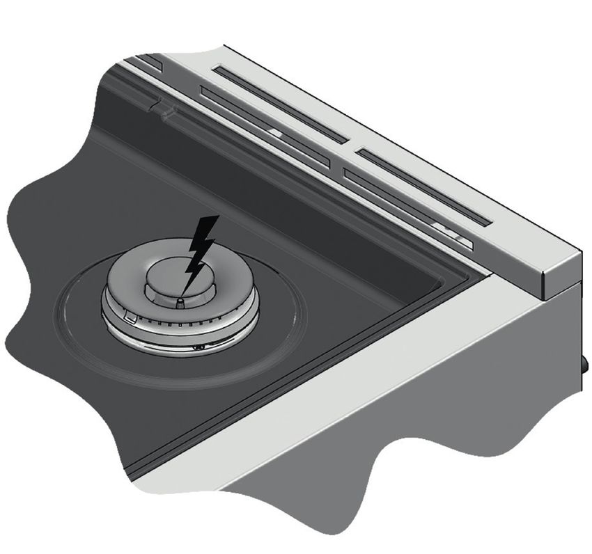
Dear Customer,

Thank you for purchasing a Fulgor Milano product. Fulgor Milano is
committed to excellence and our signature technologies provide you with
professional tools for your kitchen. One of our central philosophies is
continuous investment in research that is rooted in developing life enhancing
technology. Our goal is to deliver products that are worthy of your family
recipes and that will breathe life into your kitchen, the heart of your home.
We invite you to enjoy your new Fulgor Milano product with same amount
of care and attention that we have put into creating it.

Your Life | Our Passion
EN

                                                                    Pay attention to these symbols present in this manual:

    TABLE OF CONTENTS                                   PAGE                 DANGER
 1 - Special Warnings                                        2       You can be killed or seriously injured if you don’t
    Before Starting Installation                             2       IMMEDIATELY follow instructions.
    Mobile Home Installation                                 2
    Recreational Park Trailers                               2
                                                                             WARNING
 2 - Product Dimensions and Cutout Requirements              3
 3 - Installation Information                                9       This is the safety alert symbol. This symbol alerts you to
                                                                     potential hazards that can kill or hurt you and others. You
 4 - Installation Instructions                             10
                                                                     can be killed or seriously injured if you don’t follow these
 5 - Gas Requirement                                        11       instructions.
    Pressure Testing                                       12
    Pressure Test Method                                   12       READ AND SAVE THESE INSTRUCTIONS.
    Gas Connection                                         13
                                                                    To installer:
 6 - Conversion for LP or NG Gas                           14
                                                                    Leave these instructions with the appliance.
    Converting Appliance for Use with LP Gas               14
    Replace Injectors (two ring flame burner)              14       To customer:
    Converting Appliances for Use with NG Gas              15       Retain these instructions for future reference.
    INJECTORS POSITION                                     16
    Low Flame Adjustment                                   18
                                                                             WARNING
    Electric Gas Ignition                                  19
    The Burner Flames                                      19
                                                                     If the information in this manual is not followed exactly, a fire
 7 - Electrical Requirements                               20        or explosion may resulting in product and property damage
    General Information                                    20        and / or personal injury or death.
                                                                     Do not store or use gasoline or other flammable vapours and
    Electrical Connection                                  20
                                                                     liquids in the vicinity of this or any other appliance.
    Electrical Requirements                                21

IMPORTANT:                  Save these instructions for the local
                            electrical inspector use.

INSTALLER:                  Please leave this manual with owner
                            for future reference.

OWNER:                      Please keep this manual for future
                            reference.

GLOSSARY OF TERMS:          NG - Natural Gas
                            LP - Liquid Propane

                                                                                                                                         1
EN 1 - Special Warnings
IMPORTANT INSTRUCTION
Please read all instructions before using this appliance.
Proper installation is your responsibility. Have a qualified Copies of the standards listed may be obtained from:
technician install this rangetop. ** National Fire Protection Association One Batterymarch Park
Quincy, Massachusetts 02269
IMPORTANT *** CSA International 8501 East Pleasant Valley Rd. Cleveland,
OH 44131-5575
- Observe all governing codes and ordinances.
NOTE: This rangetop is manufactured for use with Natural
- Write down the model and serial numbers before installing
gas or Propane.
the rangetop. Both numbers are on the serial rating plate
To convert to LP (propane) or NG (natural gas), see
refer to the illustration below.
instructions in the gas conversion kit provided in the
literature package. Proper gas supply connection
must be available. See gas supply requirements.
LOCATION OF RATING PLATE WARNING
Before connecting the appliance to the gas supply line,
ensure that its gas setting is appropriate.
The type of gas adjusted and shipped from the factory is
indicated on the rating plate.
Mobile Home Installation
The installation of this appliances must conform to the
Manufactured Home Construction and Safety Standards, Title
24 CFR, Part 3280 (formerly the Federal Standard for Mobile
Home Construction and Safety; Title 24 HUD part 280); or
when such standard is not applicable, the Standard for
Manufactured Home Installations (Manufactured Home Sites,
Communities and Setups), ANSI A225.1 - latest edition, or
with local codes.
In Canada, the installation of this appliances must conform
with the current standards CAN/CSA-Z240 - latest edition, or
Before Starting Installation
with local codes.
• Check location where rangetop will be installed. The
location should be away from strong drafty areas, such as
Recreational Park Trailers
windows, doors and strong heating vents or fans.
• Electrical grounding is required. See “Electrical The installation of this appliances designed for Recreational
Requirements” Park Trailers must conform with state or other codes or, in the
absence of such codes, with the Standard for Recreational
• Assure that electrical installation is adequate and in Park Trailers, ANSI A119.5.
conformance with National Electrical Code, ANSI/
NFPA 70 - latest edition**, or Canadian Electrical Code,
part 1 C22.1 (latest edition)*** and all local codes and
ordinances.
• Assure that gas connection conforms with local codes and
ordinances. In the absence of local codes, installations
must conform with American National Standard, National
Fuel Gas Code ANSI Z223/NFPA 54 - latest edition**
Canadian CAN/ CGA_B 149.1 or CAN/CGA-149.2
latest edition**
22 - Product Dimensions and Cutout Requirements EN
PRODUCT DIMENSIONS
30” Wide Rangetop Models
29 3/4” (75.8)
7” (17.9)
2” (5) 2” (5)
30” (76.2)
29 1/2” (75.1)
27 3/8” (69.7)
16 3/8” (41.5)
10” (25.5)
7” (17.9)
8 1/8” (20.6)
2” (5) 2” (5)
min. 24” (61)
max. 25 5/8” (65)
7” (17.9)
29 3/4” (75.8)
27 3/8” (69.7)
3EN 2 - Product Dimensions and Cutout Requirements
PRODUCT DIMENSIONS
36” Wide Rangetop Models
35 3/4” (91.0)
7” (17.9)
2” (5) 2” (5)
36” (91.4)
29 1/2” (75.1)
27 3/8” (69.7)
16 3/8” (41.5)
10” (25.5)
7” (17.9)
8 1/8” (20.6)
2” (5) 2” (5)
min. 24” (61)
max. 25 5/8” (65)
7” (17.9)
35 3/4” (91.0)
27 3/8” (69.7)
42 - Product Dimensions and Cutout Requirements EN
CUTOUT REQUIREMENTS
min 48” (122)
Minimum to combustibles when
no ventilation hood is present*
A
max 13” (33)
min 30” (76.2)
to bottom of
min 18” (45.7) ventilation hood
min 6” (15.2) min 6” (15.2)
Electrical and Gas
connections
in this area
*NOTE: Ensure your installation also complies with local and national building and fire codes.
INSTALLATION WITH SEPARATOR SHEET
(61)
2 4 ” 5)
min 5 1/2” (6
x 2
ma
A
7.9)
7” (1
5EN 2 - Product Dimensions and Cutout Requirements
INSTALLATION ON SOLID SURFACE
4 5/8” (11.6) HOLE FOR ELECTRICAL 3½” (9) 5” (12.8)
HOLE FOR GAS 3½” (9) 1 3/4” ( 4.5)
2 3/4” (7.0)
4 7/8” (12.5)
7 1/2”
(19.2)
1 3/4” ( 4.5)
max 25 1/2” (65)
min 24” (61)
B
CUTOUT FOR FIXING BRAKETS
A
INSTALLATION WITHOUT SEPARATOR SHEET
(61)
2 4 ” 5)
min 5 1/2” (6
x 2
ma
A
7.9)
7” (1
2”
(5) )
2” (5
2” (5)
62 - Product Dimensions and Cutout Requirements EN
INSTALLATION ON OPEN FRAME
2” (5) 2” (5)
2” (5)
max 25 1/2” (65)
(61)
EMPTY SPACE
min 24”
2” (5)
A
CUTOUT REQUIREMENTS
If the surface of the entire back wall above the range and below the hood is not composed of a non-combustible material
then the 9” accessory back guard must be used.
*Consult local code for exact location requirements.
OPENING WIDTH A B ADDITIONAL CLEARANCES:
Rangetop 30” 30" (76.2) 24 1/4 (61.7) For island installation, maintain 2-½ in. minimum from
cutout to back edge of countertop and 3 in. minimum from
Rangetop 36” 36" (91.4) 30 3/8 (77.1) cutout to side edges of countertop (see top view).
For installation in a stepped island, 12” (30.5 cm) minimum
Note: Clearances from non-combustible materials are not clearance is required from the back or sides of the rangetop
part of the ANSI Z21.1 scope and not certied. to a combustible riser.
Clearances to non-combustible materials must The island installation is not part of the ANSI Z21.1 scope
conform with local codes or, in the absence of local and not certified.
codes, with the National Fuel Gas Code, ANSI
Z223.1/NFPA 54.
Minimum clearances: FLUSH ISLAND INSTALLATION
Above cooking surface (above 36” [91.4 cm])
BACK
• Sides - 6” (15.2 cm)
min 2 1/2” (6.3)
• Within 6” (15.2 cm) side clearance, wall cabinets no
deeper than 13” (33.0 cm) must be minimum 18” (45.7
cm) above cooking surface
• Wall cabinets directly above product must be a minimum
of 48” (122 cm) above cooking surface.
• Rear - 0” with 9 ” backguard; 0” with non-combustible
rear wall.
Below cooking surface (36” [91.4 cm] and below)
• Install with zero clearance between adjacent combustible
construction below the cooking surface and the back min 3” (7.6) min 3” (7.6)
and sides of the appliance.
7EN 2 - Product Dimensions and Cutout Requirements
Vent hood Combinations:
It is recommended that these rangetops be installed in
conjunction with a suitable overhead vent hood.
Due to the high heat capacity of this unit, particular attention
should be paid to the hood and ductwork installation to assure
it meets local building codes.
A hood with suitable capture area and capable of at least
450 cfm is suggested to effectively evacuate odors, steam and
heat. Choosing to install a hood of lower cfm or configured for
recirculating may compromise the effectiveness of eliminating
the aforementioned factors.
Note: some State / Provincial building codes will require
make up air systems be installed for hoods above a
certain cfm threshold (300 cfm is typical).
It is your responsibility to understand and comply with
the local requirements for gas, electrical and ventilation
where these appliances are being installed.
WARNING
Air curtain or other overhead hoods, which operate by
blowing a downward air flow on to a rangetop, shall not be
used in conjunction with rangetop with gas cooktop other than
when the hood and rangetop have been designed, tested
and certified by an independent test laboratory for use in
combination with each other.
Clearances to horizontal surfaces above the rangetop,
measured to the cooking surface are below. Failure to
comply may result in fire hazard.
• Installations without a hood require 48” (122) minimum
to combustibles.
• A custom hood installation with exposed horizontal
combustible surfaces must have an Auto-On feature.
• For other installations with a hood, refer to the hood
installation instructions for specific hood clearances.
CAUTION
Due to the weight and size of the rangetop and to reduce the
risk of personal injury or damage to the product:
TWO PEOPLE ARE REQUIRED FOR PROPER INSTALLATION.
83 - Installation Information EN
WARNING TOOLS WILL YOU NEED
• Excessive Weight Hazard
Use two or more people to move and install rangetop.
Failure to do so can result in back or other injury.
• Cut Hazard
Beware of sharp edges. Use the polystyrene ends when
carrying the product. Failure to use caution could result in
minor injury or cuts.
CHOOSING RANGETOP LOCATION
Carefully select the location where the rangetop will be placed.
The rangetop should be located for convenient use in the
kitchen, but away from strong drafts.
Strong drafts may be caused by open doors or windows, or by
heating and/or air conditioning vents or fans.
IMPORTANT NOTE
Remove packaging materials and literature package from the
When installing against a combustible surface, a minimum cooktop before beginning installation.
riser is required for a the rangetop, Follow all minimum Remove Installation Instructions from the literature pack and
clearances to combustible surfaces shown in the illustration read them carefully before you begin
on the previous pages.
MATERIALS PROVIDED
To eliminate the risk of burns or fire by reaching over heated
surface units, cabinet storage space located above the surface
units should be avoided. If cabinet storage is to be provided,
the risk can be reduced by installing a rangetop hood that
projects horizontally a minimum of inches beyond the bottom
of the cabinets.
Appliance
pressure Fixing brackets
regulator
Flare union Gasket
adaptor
MATERIALS REQUIRED (not provided)
Joint Sealant Pipe Fittings Shut-Off Valve
5-foot maximum length, 5/8” O.D. CSA-approved flexible
metal gas supply (3-foot maximum length in Massachusetts only)
NOTE: Purchase new flexible line; do not use previously used
flexible gas line.
9EN 4 - Installation Instructions
STEP 1 STEP 3
Install the backsplash (if provided) by the three screws on the Two clamp brackets are provided with your unit.
back and the toe kick After rangetop has been installed into the countertop, install the
brackets on the burner box as shown.
step A place the clamping screws into brackets
step B attach brackets by using the attachment screws on the
selected location of burner box, tighten screws just
enough to hold brackets in place
step C position brackets so that they are with the clamp screw
in contact with the counter top bottom
step D tighten attachment screws securely.
9” 3”
step E check that the front edge of the rangetop is parallel
to the front edge of the countertop tighten the screw
clamping against the countertop.
DO NOT OVER TIGHTEN
STEP 2
Slide the rangetop top into place.
105 - Gas Requirement EN
QUALIFIED SERVICE MAN OR GAS APPLIANCE INSTALLER
GAS SHUT OFF VALVE
MUST MAKE THE GAS SUPPLY CONNECTION.
Leak testing of the appliance shall be conducted by the installer OPEN POSITION
according to the instructions given.
You must install the supplied connection parts seen here in
this configuration to the main gas manifold on the appliance.
LY
Issues arising from a failure to do so will not be covered by SUPP
GAS
warranty.
Do not install the pressure regulator backwards as the gas will N CE
PPLIA
not flow correctly. Check that the arrow on the back points in TO A
the direction of gas flow.
Parts required for connection from gas supply to regulator are
the responsibility of the installer / owner
All supply piping, except as noted, should use common
National Pipe Thread (N.P.T.). For all pipe connections use an
approved pipe joint compound resistant to the action of LP gas.
This appliance is designed for use with NG gas or LP gas.
The gas pressure regulator is supplied with this appliance.
Appliance It must be installed in the gas ahead of the manifold entrance.
It is pre-set for use with natural gas. To use it with different
gas it must be converted, as described in the Gas Conversion
paragraph.
Appliance Flare union If at any time the appliance is to be used with a different type
pressure regulator adaptor Gasket of gas, all the conversion adjustments must be made by a
qualified technician before attempting to operate the rangetop
with that gas.
The gas should be supplied to the appliance’s pressure regulator
at line pressure between 6 and 14 inches of water column for
NG, and between 11 and 14 inches of water column for LP.
GAS REQUIREMENTS
ATTENTION NATURAL GAS WC
Manifold Pressure 5" (12.5 mb)
Use Teflon tape rated for gas applications at all threaded
connections. Min Line Pressure 6" (15 mb)
Do not overtighten the connection at the manifold or you Max Line Pressure 14" (34.9 mb), .5 psi (3.5 kPa)
could damage the gasket causing a leak.
LP GAS WC
Manifold Pressure 10” (25 mb)
WARNING Min Line Pressure 11” (27.4 mb)
Max Line Pressure 14” (34.9 mb), .5 psi (3.5 kPa)
If the line pressure supplying the appliance pressure regulator
exceeds 14 inches W.C. (any gas), an external regulator
must be installed in the gas line ahead of the appliance LOCATION OF GAS RATING PLATE
regulator to reduce the pressure to no more than 14 inches
W.C. Failure to do this can result in malfunction and damage
to the appliance.
Important Notes for Gas Connection
The appliance and its individual gas shutoff valve must be
disconnected from the gas supply piping system during any
pressure testing of that system at test pressures in excess of 1/2
psi (3.5 kPa).
The appliance must be isolated from the gas supply piping
system by closing its individual manual shut-off valve during
any pressure testing of the gas supply piping system at test
pressures equal to or less than 1/2 psi (3.5 kPa).
11EN 5 - Gas Requirement
Pressure Testing
The appliance must be isolated from the gas supply piping
IMPORTANT system by closing its individual manual shut-off valve during
any pressure testing of the gas supply piping system at test
NEVER REUSE OLD CONNECTORS WHEN INSTALLING pressures equal to or less than 1/2 PSIG (3.5 kPa).
THIS RANGETOP. This appliance, as well as its individual shut-off valve, must be
To reduce the likelihood of gas leaks, apply teflon tape or a disconnected from the gas supply piping system during any
thread compound approved for use with LP or Natural gases pressure testing of the system at test pressures in excess of 1/2
to all threaded connections. PSIG (3.5 kPa).
Apply a non-corrosive leak detection fluid to all joints and When checking appliance regulator function, make certain
fittings in the gas connection between the supply line shut-off pressure of natural gas supply is between 6 and 14 inches of
valve and the cooktop inlet. water column or, if converted for LP gas, between 11 and 14
Check for leaks! inches.
Bubbles appearing around fittings and connections will
indicate a leak. If a leak appears, turn off supply line gas THE PRESSURE TESTING SHOULD BE PERFORMED BY
shut-off valve, tighten connections, turn on the supply line gas MEANS OF THE INJECTOR THREAD ZONE
shutoff valve, and retest for leaks. Never test for gas leaks
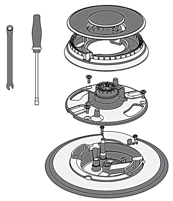
with an open flame. EXPLODED VIEW OF BURNER
NEVER TIGHTEN TO MORE THAN 35 ft lbs OF TORQUE
1
CAUTION
2
Do not attempt to attach the flexible connector directly to an
external pipe thread.
Connection requires flare union adapters.
For Massachusetts Installations:
1. Shut-off valve must be a “T” handle gas valve. A
2. Flexible gas connector must not be longer than 36 inch.
3. Not approved for installation in a bedroom or a bathroom
unless unit is direct vent.
Pressure Test Method
• Remove grate and burner cap (1).
• Remove aluminum gas spreader (2).
• Temporarily remove the injectors (A).
• Connect the pressure Test instrument into injector holder
thread zone (M6x0,75).
• Check if the cooktop has the correct pressure.
• Fix the injector removed for testing and replace the parts in
the right position.
125 - Gas Requirement EN
Gas Connection
• Thread the appliances pressure regulator with 1/2” male Unless prohibited by local codes or ordinances, a new A.G.A.
end connection both supplied with this appliance. - Certified, flexible metal appliance connector may be used to
connect this appliance to its gas supply.
• Join the pressure regulator to the entrance threads of the
The connector must have an internal diameter not less than
Gas Manifold with gasket supplied with this appliance.
nominal 1/2” NPT pipe and be no more than 5 feet in length.
The regulator is marked with a directional arrow indicating
A 1/2” NPT x 1/2” flare union adapter is required at each
correct direction of gas flow. Ensure the appliance regulator
end of the flexible connector.
is installed with the arrow pointing toward the gas manifold
If a flexible connector is used assure that both the appliance
entrance.
pressure regulator and manual shut-off valve are joined solidly
• Connect a manual shut-off valve to the gas supply in an to other permanent hard piping (either gas supply or the
accessible location for turning on or shutting off gas to the appliance manifold) so as to be physically stationary.
appliance.
• Install a coupling between the regulator and the shutoff
valve to complete the connection.
CAUTION
• Assure all pipe joint connections are gas tight.
Do not attempt to attach the flexible connector directly to an
• Check alignment of valves after connecting the cooktop to external pipe thread.
the gas supply to be sure the manifold pipe has not been Connection requires flare union adapters.
moved.
For Massachusetts Installations:
FOR ALTERNATIVE PIPING METHODS TO CONNECT THE
APPLIANCE TO THE GAS SUPPLY, A TRAINED SERVICE 1. Shut-off valve must be a “T” handle gas valve.
TECHNICIAN OR GAS APPLIANCE INSTALLER MUST 2. Flexible gas connector must not be longer than 36 inches.
MAKE THE GAS SUPPLYCONNECTION. Leak testing of the
3. Not approved for installation in a bedroom or a bathroom
appliance shall be conducted by the Installer according to the
unless unit is direct vent.
Instructions given.
GAS CONNECTION
FLARE UNION ADAPTOR APPLIANCE PRESSURE REGULATOR
FLARE UNION ADAPTOR
FLEXIBLE APPLIANCE CONNECTOR
(5 FT.) MAX, (1.52 m) MAX
MANIFOLD SHUTOFF VALVES
FLEXIBLE APPLIANCE CONNECTOR
(5 FT.) MAX, (1.52 m) MAX
APPLIANCE PRESSURE REGULATOR
MANIFOLD SHUTOFF VALVES
13EN 6 - Conversion for LP or NG Gas
Converting Appliance for Use with LP Gas Replace Injectors (two ring flame burner)
1. Remove the grates and burner caps.
WARNING
2. Remove aluminium gas spreader.
Conversion is to be performed by an AUTHORIZED 3. Remove the three screws from the simmer gas spreader (1).
SERVICER (or other qualified agency) in accordance with the 4. Remove the two screws of the injector cover (2).
manufacturer’s instructions and all codes and requirements of
5. Remove injector (A) by using a 9-32” (7 mm) nut driver
the authority having jurisdiction. Failure to follow instructions
counter clockwise.
could result in serious injury or property damage.
The qualified agency performing this work assumes 6. Remove injector (B) by using a 9-32” (7 mm) box wrench
responsibility for this conversion. counter clockwise.
7. Install the injectors supplied with this appliance in the
appropriate burner. The injectors have small numbers
CAUTION stamped on the side, this number corresponds with the
orifice diameter and its correct burner location (refer to
Before proceeding with the conversion, shut off the gas illustrations in the section: “Injectors Position”).
supply to the appliance prior to disconnecting the electrical 8. Turn clockwise to tighten (tighten to a torque of 15 to 20
power inch-lbs).
9. Replace all parts following the reverse order.
If this appliance is to converted for use with gas LP (propane 10.Save the injectors removed from the appliances for future
or butane), each of the following modifications must be use.
performed:
Gas conversion label (aluminium) to be placed on the back of EXPLODED VIEW OF BURNER
the appliance, near the data plate, after conversion has been
carried out;
1
2
A B
146 - Conversion for LP or NG Gas EN
Proceed to Pressure Regulator Conversion noting the PRESSURE REGULATOR CONVERSION
LP / Propane position to complete the conversion.
After replacing the injectors adjust the burner flame (see Low
Flame Adjustment paragraph).
Check the appearance of each burner’s flame at HILO settings, CAP
if the flame appears too large or too small make sure that all
steps were completed correctly. GASKET
NG POSITION
Converting Appliances for Use with NG Gas LP/PROPANE POSITION
If this appliance should be converted for use with gas NG
(natural gas), each of the following modifications must be
performed.
1. Convert the pressure regulator to NG position as per the
section “Pressure Regulator Conversion”.
PRESSURE REGULATOR
2. Replace all injectors following the step described on the
previous pages, observe the number stamped on the side,
this number corresponds to the orifice diameter and its
correct burner location (refer to the illustrations in section: PLUG
“Injectors Position”).
3. Adjust the burner flame (see Low Flame Adjustment section).
Check the appearance of each burner’s flame at HI - LO
settings, if the flame appears too large or too small make
sure that all steps were completed correctly.
NG LP
Pressure regulator conversion
Before replacing the regulator cap, check if the position
The appliances is designed for use with NG gas or LP gas. The of plug is suitable for the gas
gas pressure regulator is supplied. It must be installed in the
gas supply line ahead of the manifold entrance.
It is pre-set for use with the gas as indicated on the appliance
label supplied with the appliance. For use with different gas
the appliance must be converted.
For the pressure regulator conversion follow the instructions
below:
• Disconnect all electrical power, at the main circuit breaker
or fuse box.
• Shut off the gas supply to the cooktop by closing the manual
shut-off valve.
• Adjust the pressure regulator, by following the instruction
(see figure)
1. Unscrew the regulator cap
2. Unscrew the plastic conversion plug from the cap turn
over and screw back (wide section away from cap for
LP and against cap for NG) see figures below.
3. Replace the regulator cap ensuring gasket is in place.
15EN 6 - Conversion for LP or NG Gas
INJECTORS POSITION
NG- DUAL FLAME RING 30”
SIMMER 72
MAIN FLAME 180
SIMMER 72
*MAIN FLAME 180 or
*MAIN FLAME 192
NG- DUAL FLAME RING 36”
SIMMER 72
MAIN FLAME 180
SIMMER 72
*MAIN FLAME 180 or
*MAIN FLAME 192
* depending on the model
166 - Conversion for LP or NG Gas EN
INJECTORS POSITION
LP- DUAL FLAME RING 30”
SIMMER 50
MAIN FLAME 105
LP- DUAL FLAME RING 36”
SIMMER 50
MAIN FLAME 105
17EN 6 - Conversion for LP or NG Gas
Low Flame Adjustment Adjustment for Burners with one or two flame rings:
DANGER 1. Light burner and set control knob for low flame.
2. Remove control knob from valve stem.
Lighting gas burners with a match is dangerous. 3. Remove knob seat from control panel.
You should match light the burners only in an emergency.
4. Insert a slender, thin-blade screwdriver into the recess
Light a match and hold the flame near the burner you want
behind the control knob (A or B) and engage blade with
to light. Wooden matches work best.
slot in adjusting screw.
Push in and turn the control knob slowly.
Be sure you are turning the correct knob for the burner you 5. Turn adjusting screw to set flame size:
are lighting. • clockwise to reduce
• counterclockwise to increase
NOTE: If the burner does not light within five seconds, turn the 6. Replace control knob when adjustment is completed.
knob off and wait one minute before trying again.
CAUTION
If you attempt to measure the inner cone of the flame, please
use caution.
Burns could result.
This appliance is shipped from the factory with low and
medium flame settings adjusted.
If further adjustment is necessary, proceed as follows:
ADJUSTMENT FOR COOKTTOP BURNERS
A SIMMER
B MAIN FLAME
186 - Conversion for LP or NG Gas EN
Proper adjustment will produce a stable, steady blue flame of
minimum size.
The final adjustment should be checked by turning the knob
from high to low several times without extinguishing the flame.
This adjustment, at low setting, will automatically provide the
proper flame size at medium setting.
After Conversion steps have been completed, check the
appearance of each burner’s flame at the HI and LO settings,
if the flames appear too large or too small
review each step to make sure it was completed correctly.
NOTE: To obtain the correct minimum setting with LP gas,
turn clockwise tightening the valve(s) fully with the thin-blade
screwdriver into the recess behind control knob (A and / or B).
Electric Gas Ignition The Burner Flames
The gas burners use an electric ignition device located near Turn each burner on. Flames should be blue in color with no
each burner ensures burners ignite automatically. trace of yellow. The burner flames should not flutter or blow
away from the burner The inner cone of the flame should be
between 1/2” and 3/4” long.
ELECTRIC IGNITION BURNER FLAMES
1/2” to 3/4”
BURNER
See Use & Care manual for better explanation and its control.
19EN 7 - Electrical Requirements
General Information Electrical Connection
This appliance must be supplied with the proper voltage and An adequate electrical supply and outlet must be used to
frequency and connected to an individual, properly grounded operate the electrical parts of your appliance.
branch circuit, protected by a circuit breaker or fuse having
amperage as noted on the rating plate. We recommend you
have the electrical wiring and hookup of your appliance
connected by a qualified electrician. WARNING
After installation, have the electrician show you where your
main appliance disconnect is located. Check with your local
utilities for electrical codes which apply in your area. Failure to
wire your cooktop according to governing codes could result
in a hazardous condition.
If there are no codes, your appliance must be wired and fused
to meet the requirements of the National Electrical Code,
ANSI/NFPA No. 70 - Latest edition.
You can get a copy by writing:
National Fire Protection Association
Battery march Park
Quincy. MA 02269
In Canada your appliance must be wired and fused to meet Electrical Grounding Instruction Plug into a grounded 3
the requirements of the Canadian Electrical Code. prong outlet.
Be sure the installation of this product in a mobile home - Do not remove ground prong.
conforms with the Manufactured Home Construction and
Safety Standard, Title 24 CFR, Part 3280. - Do not use an adapter.
If this standard does not apply, you must follow the standard - Do not use an extension cord.
for Manufactured Home Installations, ANSI A225.1 and
Failure to follow these instructions can result in death, fire, or
Manufactured Home Installations, Sites and Communities and
electrical shock.
ANSI/NFPA 501A or with local codes.
You can get a copy of the Federal Standard by Writing:
Office of Mobile Home Standards IMPORTANT
HUD Building
451 7th Street, S.W.
FOR PERSONAL SAFETY, THIS APPLIANCE MUST BE
Washington, D.C. 24010
PROPERLY GROUNDED.
LOCATION OF RATING PLATE
The power cord of this appliance is equipped with a 3-prong
(grounding) plug which must be used with a properly grounded
3-hole outlet with a standard 120 Volt, 60 cycle AC household
current. If you do not have a 3-hole grounded outlet, have a
qualified electrician change your old one.
A grounding adaptor will be needed to convert the old one
until the outlet can be replaced. This method is only temporary,
and a qualified electrician should test it to be sure it meets
requirements.
207 - Electrical Requirements EN
Electrical Requirements
Do not under any circumstances cut or remove grounding
prong from the appliance cord. WARNING
• If cold water pipe is interrupted by plastic, non metallic
gaskets, union connections or other insulating materials,
PLUG POWER SUPPLY CORD
DO NOT use for grounding.
• DO NOT ground to a gas pipe.
• DO NOT have a fuse in the NEUTRAL or GROUNDING
circuit. A fuse in the NEUTRAL or GROUNDING circuit
could result in an electrical shock.
• Check with a qualified electrician if you are in doubt as to
whether the appliance is properly grounded.
• Failure to follow these instructions could result in serious
N
injury or death.
L
CAUTION
Do not repair or replace any part of the appliance unless
specifically recommended in the manual. All other servicing
should be done by a qualified technician. This may reduce
Grounding prong the risk of personal injury and damage to the appliance.
Never modify or alter the construction of the appliance by
removing panels, wire covers, screws, or any other part of
the product.
21EN 22
FR

                                                                  Veuillez prêter attention à ces symboles que vous rencontrerez
                                                                  dans ce manuel :

    TABLES DES MATIERES                                PAGE                 DANGER
 1 - Avertissement Spéciaux                                2       Si vous ne suivez pas IMMEDIATEMENT ces instructions,
    Avant de Procéder à l’Installation                     2       vous courez le risque de mourir ou d’être sérieusement
    Installation autocaravane                              2       blessé.
    Micro-maisons préfabriquées                            2
 2 - Dimensions et Dispositions pour la Découpe            3                AVERTISSEMENT
 3 - Consignes d’installation                              9
                                                                   Ce symbole signifie que la sécurité est en danger. Il signale
 4 - Instructions d’Installation                          10       les risques potentiels qui peuvent entraîner la mort ou des
 5 - Conditions Requires Gaz                              11       blessures à l’opérateur ou aux autres.
                                                                   Si vous ne suivez pas ces instructions à la lettre, vous courez
    Vérification de la Pression                          12        le risque de mourir ou d’être sérieusement blessé.
    Méthode de Test de Pression                          12
    Raccordement du Gaz                                  13       BIEN LIRE CES INSTRUCTIONS ET LES CONSERVER.
 6 - Conversion Gaz PL ou Gaz Naturel                     14
     Conversion de l’Appareil pour Fonctionner au                 À l’installateur :
     Gaz PL                                              14       Laissez ces instructions avec l’appareil.
     Remplacez un injecteur (brûleur avec deux
     anneaux de flamme)                                  14       Au client :
     Conversion des Appareils pour Une Utilisation                Gardez ces instructions comme référence future.
     avec Gaz Naturel                                    15
    Position des Injecteurs                              16
                                                                            AVERTISSEMENT
    Réglage Petite Flamme                                18
    Allumage à gaz électrique                            19        Le respect minutieux des indications fournies dans ce manuel
    Les Flammes du Brûleur                               19        est indispensable pour éviter le risque de feu ou d’explosion
                                                                   susceptible d’endommager les biens et les produits et de
 7 - Conditions Requises Electricité                      20       provoquer des blessures, voire même la mort.
    Information Général                                  20        Ne pas stocker ou utiliser de l’essence ou d’autres liquides
    Branchement Electrique                               20        inflammables à proximité de cet appareil ou de tout autre
                                                                   appareil électroménager.
    Requises Electricité                                 21

IMPORTANT:         Gardez ces instructions pour une utilization
                   d’inspection électrique locale

INSTALLATEUR:      Veuillez laisser ce manuel au propriétaire
                   pour de futures références.

PROPRIETAIRE:      Veuillez garder ce manuel pour de futures
                   références.

LEXIQUE:           NG - Gaz naturel
                   LP - Propane liquide

                                                                                                                                     1
FR 1 - Avertissement Spéciaux
INSTRUCTION IMPORTANT
Veuillez lire les instructions avant toute utilisation.
Il est de votre responsabilité d’installer l’appareil correctement. être conforme au Standard National Américain, à la
Confiez l’installation de cette cuisinières à un technicien Réglementation Nationale Essence Gaz ANSI Z223.1
qualifié. – NFPA 54 dernière édition** ou CAN/CGA-149.2
dernière édition***.
AVERTISSEMENT
Vous pouvez demander une copie des standards répertoriés à:
- Respecter les règlements et ordonnances en vigueur. ** National Fire Protection Association One Batterymarch
Park Quincy, Massachusetts 02269
- Avant l’installation de la cuisinière, noter le modèle et
les numéros de série. Les deux numéros se trouvent sur *** CSA International 8501 East Pleasant Valley Rd.
la plaque de données dans la position indiquée dans la Cleveland, OH 44131 – 5575
figure ci-dessous.
NOTE: Cette cuisinières est fabriquée pour fonctionner au gaz
naturel*.
Si elle doit être raccordée au gaz propane/PL, ffectuez
POSITION DE LA PLAQUE SIGNALÉTIQUE la conversion en suivant les instructions rapportées dans
le kit de conversion gaz fourni avec les explications.
Une canalisation de fourniture de gaz correcte doit être
disponible. Voir «Conditions requises fourniture gaz».
WARNING
Avant de raccorder le dispositif à la ligne d’amenée du gaz,
vérifier que le type de gaz est réglé correctement. Le type de
gaz programmé et envoyé de l’usine est indiqué sur la plaque
signalétique.
Installation autocaravane
L’installation de cette table de cuisson doit être conforme
aux Normes de Construction et de Sécurité des Habitations,
titre 24 CFR, Partie 3280 (jadis la Norme Fédérale pour la
Construction et la Sécurité des Autocaravanes; titre 24HUD
partie 280); ou lorsque de telles normes ne sont pas
applicables, la Norme pour les Installations des Habitations
Avant de Procéder à l’Installation (Emplacements, Communautés et Structures Habitations),
ANSI 225.1 - dernière édition ou aux réglementations locales.
• Vérifiez l’endroit où la cuisinières sera installée. La table de
cuisson ne doit pas se trouver dans une zone de courants Au Canada, l’installation de cette table de cuisson doit être
d’air forts, par exemple de fenêtres ou de portes ni près de conforme aux normes en vigueur CAN/CSA-Z240 - dernière
calorifères ou de ventilateurs. édition ou aux réglementations locales.
• L’appareil doit nécessairement être relié à la terre. Voir
«Conditions requises électricité».
• Veuillez vous assurer que l’installation électrique est Micro-maisons préfabriquées
adéquate et conforme à la Réglementation Électrique
Nationale ANSI/NFPA 70 – dernière édition** ou à la L’installation de ces dispositifs conçus pour micro-maisons
Réglementation Électrique du Canada, C22.1 – 1982 et préfabriquées doit se faire conformément aux réglementations
C22.2 N° 01982 (ou dernière édition)*** et à tous les nationales ou autres ou, à défaut, à la norme en matière de
règlements et ordonnances en vigueur localement. micro-maisons préfabriquées ANSI A119.5.
• Assurez-vous que le raccordement de gaz est conforme
aux règlements et ordonnances en vigueur localement.
En l’absence de règlements locaux, l’installation doit
22 - Dimensions et Dispositions pour la Découpe FR
DIMENSIONS DU PRODUIT
Modèles de cuisinière 30”
29 3/4” (75.8)
7” (17.9)
2” (5) 2” (5)
30” (76.2)
29 1/2” (75.1)
27 3/8” (69.7)
16 3/8” (41.5)
10” (25.5)
7” (17.9)
8 1/8” (20.6)
2” (5) 2” (5)
min. 24” (61)
max. 25 5/8” (65)
7” (17.9)
29 3/4” (75.8)
27 3/8” (69.7)
3FR 2 - Dimensions et Dispositions pour la Découpe
DIMENSIONS DU PRODUIT
Modèles de cuisinière 36”
35 3/4” (91.0)
7” (17.9)
2” (5) 2” (5)
36” (91.4)
29 1/2” (75.1)
27 3/8” (69.7)
16 3/8” (41.5)
10” (25.5)
7” (17.9)
8 1/8” (20.6)
2” (5) 2” (5)
min. 24” (61)
max. 25 5/8” (65)
7” (17.9)
35 3/4” (91.0)
27 3/8” (69.7)
42 - Dimensions et Dispositions pour la Découpe FR
DISPOSITIONS POUR LA DÉCOUPE
min 48'' (122)
Minimum sur combustibles en
l'absence de hotte de ventilation*
A
max 13” (33)
min 30” (76.2) de
distance avec le
min 18” (45.7) fond de la hotte
d'aération
min 6” (15.2) min 6” (15.2)
Raccordements pour
électricité et gaz
dans cette zone
*REMARQUE : Assurez-vous que votre installation est également conforme aux codes locaux et nationaux du bâtiment et de
prévention contre les incendies.
INSTALLATION AVEC PLAQUE DE SEPARATION
(61)
2 4 ” 5)
min 5 1/2” (6
x 2
ma
A
7.9)
7” (1
5FR 2 - Dimensions et Dispositions pour la Découpe
INSTALLATION SUR UNE SURFACE SOLIDE
4 5/8” (11.6) TROU POUR CÂBLAGE 3½” (9) 5” (12.8)
TROU POUR LE GAZ 3½” (9) 1 3/4” ( 4.5)
2 3/4” (7.0)
4 7/8” (12.5)
7 1/2”
(19.2)
1 3/4” ( 4.5)
max 25 1/2” (65)
min 24” (61)
B
DECOUPES POUR ETRIERS DE FIXATION
A
INSTALLATION SANS PLAQUE DE SEPARATION
(61)
2 4 ” 5)
min 5 1/2” (6
2
max
A
7.9)
7” (1
2”
(5) )
2” (5
2” (5)
62 - Dimensions et Dispositions pour la Découpe FR
INSTALLATION SUR UNE STRUCTURE OUVERTE
2” (5) 2” (5)
2” (5)
max 25 1/2” (65)
(61)
VIDE
min 24”
2” (5)
A
DISPOSITIONS POUR LA DÉCOUPE
Si la surface du mur arrière tout entier au-dessus de la cuisinière et au-dessous de la hotte n’est pas composée d’un
matériau incombustible, la protection arrière accessoire de 9 pouces doit être utilisée.
*Consulter les réglementations locales pour les exigences exactes de localisation.
LARGEUR A B • Installation à dégagement nul entre la construction
D’OUVERTURE combustible adjacente sous la surface de cuisson et les
parties arrière et latérale de l’appareil.
Cuisinière 30 po 30" (76.2) 24 1/4 (61.7)
Cuisinière 36 po 36" (91.4) 30 3/8 (77.1) ESPACE SUPPLÉMENTAIRES:
Pour une installation en îlot, maintenir une distance minimum
de 6.3 cm (2 ½ po) entre le bord et le dos du comptoir et
Remarque: Les distances par rapport aux matières non 7.6 cm (3 po) minimum sur les côtés du comptoir (voir vue
combustibles n’entrent pas dans le cadre de de dessus).
l’ANSI Z21.1 et ne sont pas certiées. Pour une installation sur un îlot, un espace de minimum 12”
La distance par rapport aux matériaux non (30.5 cm) est nécessaire de l’arrière ou des côtés de la
combustible doit respecter les réglementations cuisinière pour le brûleur.
locales ou, en l’absence de celles-ci, avec le L’installation de îlot ne fait pas partie de la norme ANSI
« National Fuel Gas Code », ANSI Z223.1/ Z21.1 portée et pas certié.
NFPA 54.
Dégagements minimums d’une construction: INSTALLATION ÉBARBER
Au-dessus de la surface de cuisson [au-dessus de 36 po (91.4 cm)]
DOS
• Côtés - 6 po (15.2 cm)
min 2 1/2” (6.3)
• Avec un dégagement latéral de 6 po (15.2 cm) ou moins,
les placards muraux ne mesurant pas plus de 13 po (33
cm) de profondeur doivent se trouver à 18 po (45.7 cm)
minimum au-dessus de la surface de cuisson
• Les armoires murales juste au-dessus du produit doivent
se trouver à 48 po (122 cm) minimum au-dessus de la
surface de cuisson
• Arrière - 0 po avec dosseret de 9 po ou étagère
supérieure; 0 po avec paroi arrière non combustible.
Sous la plaque de cuisson (36” [91.4 cm] et au-dessous) min 3” (7.6) min 3” (7.6)
7FR 2 - Dimensions et Dispositions pour la Découpe
Disposition de hotte d’extraction:
Il est recommandé d’installer ces cuisinières en conjonction
avec une hotte à évacuation appropriée en hauteur. En raison
de la capacité thermique élevée de cet appareil, une attention
particulière doit être prêtée à l’installation de la hotte et des
conduits pour s’assurer qu’elle respecte les codes du bâtiment
locaux.
Une hotte avec une zone de capture appropriée et capable
d’au moins 450 cfm est suggérée pour évacuer efficacement
les odeurs, la vapeur et la chaleur. Le choix d’installer une
hotte de cfm inférieure ou configurée pour la recirculation peut
compromettre l’élimination efficace des facteurs susmentionnés.
Remarque : certains codes de bâtiment locaux / nationaux
exigent l’installation de systèmes d’air d’appoint
pour les hottes au-dessus d’un certain seuil de
cfm (300 cfm est typique).
Il est de votre responsabilité de comprendre et
de respecter les exigences locales en matière
de gaz, d’électricité et de ventilation où ces
appareils sont installés.
AVERTISSEMENT
Les rideaux d’air ou les hottes de cuisinières qui projettent
un courant d’air descendant vers la table de cuisson, ne
doivent pas etres utilises avec des appareils à gaz, sauf si
la hotte et l’appareil ont ete concus, testes et repertories par
un laboratoire d’essai independant pour pouvoir fonctionner
conjointement.
Il faut prévoir les dégagements ci-dessous par rapport
aux surfaces horizontales qui se trouvent au-dessus de la
cuisinière.
Le non-respect de cette consigne pourrait présenter un risque
d’incendie.
• Pour les installations dépourvues de hotte, prévoyez un
espace minimum de 48” (122) entre l’appareil et tout
élément inflammable situé au-dessus de celui-ci.
• Il est possible d’installer une hotte spéciale à proximité
d’éléments horizontaux inflammables dans la mesure
où celle-ci dispose d’une fonction de mise en marche
automatique.
• Pour obtenir les spécifications relatives aux espaces
d’autres installations pourvues d’une hotte, veuillez vous
reporter aux instructions fournies avec celle-ci
ATTENTION
Afin d’éviter tout risque de blessure ou d’endommagement
de l’appareil et compte tenu du poids et de la taille de la
cuisinière:
DEUX PERSONNES SONT NÉCESSAIRES POUR UNE
INSTALLATION ADÉQUATE DES CUISINIÈRES.
83 - Consignes d’installation FR
Avant de commencer l’installation, enlevez les matériaux
AVERTISSEMENT d’emballage et les manuels d’explication sur la table de
cuisson; puis retirez du manuel d’explication, les instructions
• Risque du fait du poids excessif concernant l’installation et lisez-les avec attention.
Soyez à deux personnes ou plus pour porter et installer la
cuisinières. Sinon, vous risquez de vous blesser au dos ou
de subir d’autres blessures. MATÉRIEL FOURNI
• Risque de coupure
Méfiez-vous des bords tranchants et des extrémités du
polystyrène lorsque vous portez le produit. Sinon, vous
risquez de vous couper ou de vous faire légèrement mal.
CHOIX DE LA POSITION DE LA CUISINIÈRE
Choisissez attentivement l’emplacement d’installation de la Régulateur de
cuisinière. Etriers de fixation
pression appareil
La cuisinière doit être positionnée pour être utilisée dans la
cuisine, mais loin des courants d’air.
Une porte ou une fenêtre ouvertes, l’air mis en mouvement par Adaptateur de Joint
les ventilateurs de chauffage/climatisation peuvent causer des raccord évasé d’étanchéité
courants d’air forts.
NOTE IMPORTANTE MATÉRIEL FOURNI (non fourni)
Si vous installez la cuisinière contre une surface combustible,
veillez à prévoir un minimum de rehausse.
Respectez toutes les distances par rapport aux surfaces
combustibles qui sont indiquées dans les pages précédentes
Scellant à joint Raccords de tuyau Clapet de fermeture
Pour éliminer le risque de brûlure ou d’incendie à cause Tuyau métallique flexible d’alimentation de gaz agréé CSA de
d’une surchauffe de la surface des unités, évitez de placer 1.58 cm de diamètre et d’une longueur maximale de 1.5 m (5
une armoire de rangement au-dessus de l’unité. Si vous avez pieds) (Longueur maximum de 90 cm (3 pieds) dans le
une armoire au-dessus de la cuisinière, vous pouvez réduire Massachusetts uniquement)
le risque en installant à une certaine distance au-dessous de NOTE: procurez-vous un tuyau flexible neuf, n’utilisez pas un tuyau
la partie inférieure de l’armoire un écran de protection qui ayant déjà été utilisé.
projette horizontalement.
LES OUTILS DONT VOUS AUREZ BESOIN
9FR 4 - Instructions d’Installation
ÉTAPE 1 ÉTAPE 3
Installez le dosseret (si fourni) au moyen de trois vis dans la 2 étriers de fixation sont fournis avec l’unité.
partie postérieure et la plinthe Une fois la table de cuisson encastrée dans le plan de travail,
fixez les étriers sur la caisse du brûleur comme indiqué.
Etape A: placez les vis de fixation dans les étriers.
Etape B: attachez les étriers par des vis de fixation aux
endroits choisis sur la boîte du brûleur, serrez les vis
juste assez pour tenir en place les étriers.
Étape C: positionnez les étriers et les vis de fixation de sorte
qu’ils soient au contact du bas du plan de travail.
Étape D: bien serrer les vis de fixation.
9” 3”
Étape E: vérifiez que le bord antérieur de la table de cuisson
est bien parallèle au bord du plan de travail, serrez
la vis de fixation contre le plan de travail.
BIEN SERRER MAIS PAS TROP FORT
ÉTAPE 2
Faire glisser la cuisinière pour la mettre en place.
105 - Conditions Requires Gaz FR
LE RACCORDEMENT À LA CONDUITE DE GAZ DOIT ÊTRE individuel de fermeture du gaz, lors de toute vérification de
EFFECTUÉ PAR UN TECHNICIEN D’ENTRETIEN QUALIFIÉ OU UN pression du système de canalisation de gaz à des pressions
INSTALLATEUR DE GAZ. de test égales ou inférieures à ½ psi (3.5 kPa).
La vérification de fuites de l’appareil doit être effectuée par
ROBINET D’ARRET DU GAZ
l’installateur selon les instructions données.
Vous devez installer les pièces de raccordement fournies
indiquées ici au collecteur principal de gaz de l’appareil. Les POSITION OUVERT
problèmes résultant de la non application de ceci ne seront
pas couverts par la garantie.
GAZ
Ne pas installer le régulateur de pression en contre-courant car TIO N EN
ENTA
le gaz ne passera pas correctement. Vérifier que la flèche à ALIM
l’arrière pointe en direction du flux de gaz.
Les pièces nécessaires pour le raccordement à l’alimentation en REIL
L’APPA
gaz sont de la responsabilité de l’installateur/du propriétaire VERS
Toutes les canalisations, sauf celles spécifiées diversement,
doivent utiliser du Filetage Conduite National normal (N.P.T.).
Appareil Pour tous les raccordements de conduite, utilisez un compound
de joint de conduite homologué résistant à l’action du gaz PL.
Cet appareil est conçu pour être utilisé avec le régulateur de
pression du gaz qui vous est fourni.
Régulateur de Adaptateur Joint Il doit être installé sur la canalisation, en avant de l‘entrée du
pression raccordement tuyau de gaz. Il est préréglé pour fonctionner au gaz naturel
de l’appareil brûleur et doit être converti, comme décrit en ‘’Conversion Gaz’’, s’il
doit fonctionner au gaz PL.
Cet appareil est conçu pour fonctionner à une pression de 5
pouces de colonne d’eau sur le gaz naturel ou s’il fonctionne
au gaz PL (propane ou butane) à une pression de 10 pouces
de colonne d’eau. Bien s’assurer que cet appareil est livré et
ATTENTION équipé avec le type de gaz pour lequel il a été conçu. Cet
appareil a été réglé en usine pour fonctionner au gaz naturel.
Si pour une raison ou une autre, vous deviez utiliser un autre
Utiliser du ruban Téflon adapté pour les applications avec type de gaz, n’essayez pas de faire fonctionner la cuisinièr
gaz sur tous les raccords filetés. avec le gaz différent mais appelez un technicien spécialisé
Ne pas trop serrer le raccord au collecteur. Cela pourrait qui effectuera tous les réglages de conversion décrits en
endommager le joint et causer des fuites. ‘’Conversion Gaz’’.
Le gaz naturel doit arriver au régulateur de pression de
l’appareil à une pression de conduite entre 6 et 14 pouces de
AVERTISSEMENT colonne d’eau ou si converti au gaz PL entre 11 et 14 pouces.
Si la conduite fournissant le régulateur de pression de EXIGENCES D’ALIMENTATION EN GAZ
l’appareil a une pression de plus de 14 pouces C.E. (pour GAZ NATUREL CE (Colonne d’eau)
n’importe quel gaz), il est nécessaire d’installer un régulateur Indicateur de Pressure 5 po (12,5 mb)
externe sur la conduite de gaz, en avant du régulateur de Pression min. de la conduite 6 po (15 mb)
l’appareil, afin de réduire la pression à 14 pouces C.E. Pression max. de ligne 14 po CE (34.9 mb),
ou moins. Si vous ne le faisiez pas, vous risqueriez des 0.5 lb/po² ( 3.5 kPa)
dysfonctionnements de l’appareil et des dommages.
GAZ PL CE (Colonne d’eau)
Notes importantes pour le raccordement à la canalisation Indicateur de Pressure 10 po (25 mb)
du gaz Pression min. de la conduite 11 po (27,4 mb)
L’appareil et son robinet individuel de fermeture du gaz Pression max. de ligne 14 po CE (34.9 mb),
doivent être débranchés des canalisations de gaz durant toute 0.5 lb/po² ( 3.5 kPa)
vérification de pression de ce système, à des pressions de
test allant au-delà de ½ psi (3.5 kPa). Vous devez également
isoler l’appareil des canalisations de gaz en fermant le robinet
11FR 5 - Conditions Requires Gaz
ENDROIT DE LA PLAQUE DE GAZ Vérification de la Pression
Vous devez isoler l’appareil des canalisations de gaz en
fermant le robinet individuel de fermeture du gaz lors de tout
test de pression du système de canalisation de gaz à des
pressions de test égales ou inférieures à ½ psig (3,5kPa).
Cet appareil et son robinet individuel de fermeture du gaz
doivent être débranchés des canalisations de gaz durant tout
test de pression de ce système à des pressions de test allant au-
delà de ½ psig (3.5kPa). Lorsque vous vérifiez la fonction du
régulateur de l’appareil, bien vous assurer que le gaz naturel
est fourni à une pression entre 6 et 14 pouces de colonne
d’eau et si converti au gaz PL entre 11 et 14 pouces.
LE TEST DE PRESSION SOIT ETRE EFFECTUE EN EMPLOYANT
LA ZONE DE FILETAGE DE L’INJECTEUR
IMPORTANT VUE EXPLOSÉE DU BRÛLEUR
NE JAMAIS RÉUTILISER DE VIEUX RACCORDS POUR
INSTALLER CET APPAREIL.
Afin de limiter les fuites de gaz possibles, appliquez un
ruban adhésif téflon ou un compound de filetage homologué
pour l’emploi avec du gaz naturel ou du gaz PL sur tous les 1
raccords filetés.
Appliquez un fluide non-corrosif de détection de fuite sur tous
les joints et raccords de la conduite de gaz entre le robinet de
fermeture du gaz et l’entrée de la table de cuisson. Vérifiez
qu’il n’y a pas de fuites! Des bulles qui se forment autour 2
des joints et des raccords indiquent la présence d’une fuite.
Dans ce cas, fermez le robinet de fermeture du gaz, serrez
les raccords, ouvrez à nouveau le robinet de fermeture et
vérifiez s’il y a encore des fuites. Ne jamais vérifier s’il y a
des fuites avec une flamme directe.
A
NE JAMAIS SERRER À PLUS DE 35 ft Ibs (pieds livre) DE
TORSION.
CAUTION
Méthode de Test de Pression
N’essayez pas de raccorder le connecteur flexible
directement à un tuyau fileté extérieur. • Enlevez la grille et le chapeau du brûleur (1).
Il est nécessaire d’utiliser des adaptateurs évasés.
Pour Massachusetts Installations : • Enlevez le diffuseur aluminium de gaz (2).
• Enlevez les injecteurs temporaires (A).
1. La vanne de fermeture doit être un robinet à gaz à • Connectez l’instrument de test sur la zone de filetage du
poignée en T. porte-injecteur(M6x0.75).
2. Le connecteur gaz flexible ne doit pas avoir plus de 36 • Vérifiez si la table de cuisson a une pression correcte.
pouces de long.
• Fixez l’injecteur enlevé pour le test et replacez les pièces
3. L’installation dans une chambre ou une salle de bains dans leur bonne position.
n’est pas permise si l’unité n’est pas à évent direct.
12You can also read