AXC/AXLT/AXS/AXDL OPERATING MANUAL SERIES BETRIEBSANWEISUNG BAUREIHEN MODE D EMPLOI SÉRIE - MN systems
←
→
Page content transcription
If your browser does not render page correctly, please read the page content below
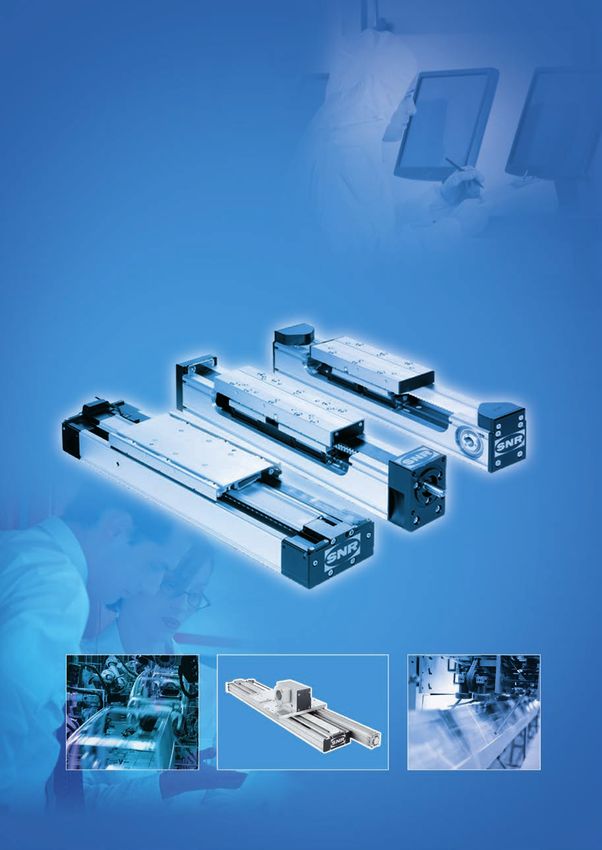
OPERATING MANUAL SERIES
BETRIEBSANWEISUNG BAUREIHEN
          MODE D´EMPLOI SÉRIE
          AXC/AXLT/AXS/AXDL
Manufacturer
SNR WÄLZLAGER GMBH
Friedrich-Hagemann-Straße 66
D-33719 Bielefeld
Tel.: +49 (0) 5 21/9 24 00-0
Fax: +49 (0)5 21/9 24 00 90

email: linear.motion@ntn-snr.com
www.ntn-snr.com
Contents
Product overview . . . . . . . . . . . . . . . . . . . . . . . . . . . . . . . . . . . . . . . . . . . . . . . . . . . . . . . . . . . . .                   4

Safety
      • General safety instructions. . . . . . . . . . . . . . . . . . . . . . . . . . . . . . . . . . . . . . . . . . . . . . . . . . . . . . . . . . 6
      • Intended use. . . . . . . . . . . . . . . . . . . . . . . . . . . . . . . . . . . . . . . . . . . . . . . . . . . . . . . . . . . . . . . . . . . . . 6

Transport and storage
      • Transport and storage provisions. . . . . . . . . . . . . . . . . . . . . . . . . . . . . . . . . . . . . . . . . . . . . . . . . . . . . 7

Assembly instruction and start-up
      • Linear axes assembly and mounting . . . . . . . . . . . . . . . . . . . . . . . . . . . . . . . . . . . . . . . . . . . . . . . . . . 7
      • Notice for linear axis start-up. . . . . . . . . . . . . . . . . . . . . . . . . . . . . . . . . . . . . . . . . . . . . . . . . . . . . . . . 8

Drive adaption . . . . . . . . . . . . . . . . . . . . . . . . . . . . . . . . . . . . . . . . . . . . . . . . . . . . . . . . . . . . . . . . .             9

Motor mounting
      • Maximum driving torques. . . . . . . . . . . . . . . . . . . . . . . . . . . . . . . . . . . . . . . . . . . . . . . . . . . . . . . . . .         10
      • Motor mounting to linear axes with toothed belt drive and clutch housing. . . . . . . . . . . . . . . . . . . .                                    12
      • Motor mounting to linear axes with timing belt drive and planetary gearbox. . . . . . . . . . . . . . . . . . .                                    13
      • Motor mounting to linear axes and linear tables with screw-type drive. . . . . . . . . . . . . . . . . . . . . . .                                 14
      • Motor mounting to belt drive . . . . . . . . . . . . . . . . . . . . . . . . . . . . . . . . . . . . . . . . . . . . . . . . . . . . . . .         15

Switches
      • Circuit diagrams . . . . . . . . . . . . . . . . . . . . . . . . . . . . . . . . . . . . . . . . . . . . . . . . . . . . . . . . . . . . . . . . . 17

Maintenance and lubrication
      • General maintenance and service instructions. . . . . . . . . . . . . . . . . . . . . . . . . . . . . . . . . . . . . . . . . .                    18
      • Brush scraper replacement – AXC series. . . . . . . . . . . . . . . . . . . . . . . . . . . . . . . . . . . . . . . . . . . . . .                  18
      • Exchanging the cover strip for series AXC. . . . . . . . . . . . . . . . . . . . . . . . . . . . . . . . . . . . . . . . . . . . .                 19
      • Exchanging the cover strip for series AXDL. . . . . . . . . . . . . . . . . . . . . . . . . . . . . . . . . . . . . . . . . . . .                  20
      • Maintenance intervals and lubricant quantities . . . . . . . . . . . . . . . . . . . . . . . . . . . . . . . . . . . . . . . . .                   21
      • Lubricants for screw drives and/or profiled rail bearings. . . . . . . . . . . . . . . . . . . . . . . . . . . . . . . . . .                       27
      • Lubricants for roller bearings . . . . . . . . . . . . . . . . . . . . . . . . . . . . . . . . . . . . . . . . . . . . . . . . . . . . . . .       28
      • Automatic lubricant dispenser . . . . . . . . . . . . . . . . . . . . . . . . . . . . . . . . . . . . . . . . . . . . . . . . . . . . . .          28
      • Central lubrication connection . . . . . . . . . . . . . . . . . . . . . . . . . . . . . . . . . . . . . . . . . . . . . . . . . . . . . .         28
      • Lubricating the gear rack . . . . . . . . . . . . . . . . . . . . . . . . . . . . . . . . . . . . . . . . . . . . . . . . . . . . . . . . . .      29

Declaration of incorporation
      • Declaration of incorporation for partly completed machinery
        in the sense of machinery declaration 2006/42/EG . . . . . . . . . . . . . . . . . . . . . . . . . . . . . . . . . . . . . . 85

Assembly drawing with parts list . . . . . . . . . . . . . . . . . . . . . . . . . . . . . . . . . . . . . . . . .                                         88

                                                                               1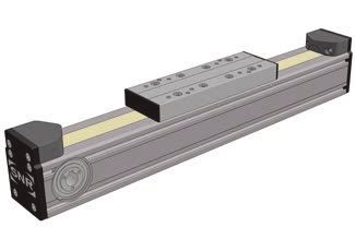
Inhalt
Produktübersicht. . . . . . . . . . . . . . . . . . . . . . . . . . . . . . . . . . . . . . . . . . . . . . . . . . . . . . . . . . . . .                   31

Sicherheit
      • Allgemeine Sicherheitshinweise. . . . . . . . . . . . . . . . . . . . . . . . . . . . . . . . . . . . . . . . . . . . . . . . . . . . . 33
      • Bestimmungsgemäße Verwendung . . . . . . . . . . . . . . . . . . . . . . . . . . . . . . . . . . . . . . . . . . . . . . . . . . 33

Transport und Lagerung
      • Vorkehrungen bei Transport und Lagerung. . . . . . . . . . . . . . . . . . . . . . . . . . . . . . . . . . . . . . . . . . . . . 34

Montageanleitung und Inbetriebnahme
      • Montage und Befestigung der Linearachsen. . . . . . . . . . . . . . . . . . . . . . . . . . . . . . . . . . . . . . . . . . . 34
      • Hinweise zur Inbetriebnahme der Linearachse. . . . . . . . . . . . . . . . . . . . . . . . . . . . . . . . . . . . . . . . . . 35

Antriebsadaption. . . . . . . . . . . . . . . . . . . . . . . . . . . . . . . . . . . . . . . . . . . . . . . . . . . . . . . . . . . . .                   36

Motormontage
      • Maximale Antriebsmomente. . . . . . . . . . . . . . . . . . . . . . . . . . . . . . . . . . . . . . . . . . . . . . . . . . . . . . . .             37
      • Motormontage an Linearachsen mit Zahnriementrieb und Kupplungsglocke. . . . . . . . . . . . . . . . . .                                             39
      • Motormontage an Linearachsen mit Zahnriementrieb und Planetengetriebe . . . . . . . . . . . . . . . . . .                                           40
      • Motormontage an Linearachsen und Lineartischen mit Gewindetrieb. . . . . . . . . . . . . . . . . . . . . . . .                                      41
      • Motormontage am Umlenkriementrieb. . . . . . . . . . . . . . . . . . . . . . . . . . . . . . . . . . . . . . . . . . . . . . . .                    42

Schalter
      • Schaltbilder. . . . . . . . . . . . . . . . . . . . . . . . . . . . . . . . . . . . . . . . . . . . . . . . . . . . . . . . . . . . . . . . . . . . . 44

Wartung und Schmierung
      • Allgemeine Wartungs- und Instandhaltungshinweise. . . . . . . . . . . . . . . . . . . . . . . . . . . . . . . . . . . . .                           45
      • Austausch der Bürstenabstreifer bei Baureihe AXC. . . . . . . . . . . . . . . . . . . . . . . . . . . . . . . . . . . . . .                         45
      • Austausch des Abdeckbandes bei Baureihe AXC . . . . . . . . . . . . . . . . . . . . . . . . . . . . . . . . . . . . . . .                           46
      • Austausch des Abdeckbandes bei Baureihe AXDL . . . . . . . . . . . . . . . . . . . . . . . . . . . . . . . . . . . . . .                            47
      • Wartungsintervalle und Schmiermittelmengen. . . . . . . . . . . . . . . . . . . . . . . . . . . . . . . . . . . . . . . . . .                       48
      • Schmierfette Gewindetrieb und/oder Profilschienenführung. . . . . . . . . . . . . . . . . . . . . . . . . . . . . . .                               54
      • Schmieröle für Laufrollenführung. . . . . . . . . . . . . . . . . . . . . . . . . . . . . . . . . . . . . . . . . . . . . . . . . . . .             55
      • Automatischer Schmierstoffspender . . . . . . . . . . . . . . . . . . . . . . . . . . . . . . . . . . . . . . . . . . . . . . . . .                 55
      • Zentralschmieranschluss . . . . . . . . . . . . . . . . . . . . . . . . . . . . . . . . . . . . . . . . . . . . . . . . . . . . . . . . . .         55
      • Schmierung der Zahnstangen. . . . . . . . . . . . . . . . . . . . . . . . . . . . . . . . . . . . . . . . . . . . . . . . . . . . . . .             56

Einbauerklärung
      • Einbauerklärung für eine unvollständige Maschine
        (Maschinery directive 2006/42/EG). . . . . . . . . . . . . . . . . . . . . . . . . . . . . . . . . . . . . . . . . . . . . . . . . . . 86

Zusammenbauzeichnung mit Stückliste . . . . . . . . . . . . . . . . . . . . . . . . . . . . . . .                                                           88

                                                                             2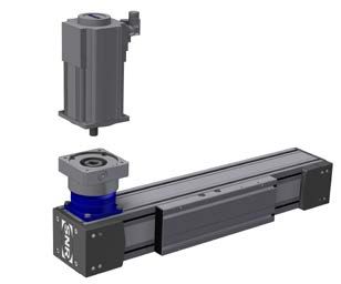
Sommaire
Caractéristiques générales des produit . . . . . . . . . . . . . . . . . . . . . . . . . . . . . . . .                                                  58

Sécurité
     • Consignes générales de sécurité. . . . . . . . . . . . . . . . . . . . . . . . . . . . . . . . . . . . . . . . . . . . . . . . . . . . 60
     • Utilisation conforme . . . . . . . . . . . . . . . . . . . . . . . . . . . . . . . . . . . . . . . . . . . . . . . . . . . . . . . . . . . . . . 60

Transport et stockage
     • Précautions pour le transport et le stockage. . . . . . . . . . . . . . . . . . . . . . . . . . . . . . . . . . . . . . . . . . . 61

Notice de montage et de mise en service
     • Montage et fixation des axes linéaires. . . . . . . . . . . . . . . . . . . . . . . . . . . . . . . . . . . . . . . . . . . . . . . . 61
     • Indications sur la mise en service de l'axe linéaire. . . . . . . . . . . . . . . . . . . . . . . . . . . . . . . . . . . . . . . 62

Périphérie d'entraînement . . . . . . . . . . . . . . . . . . . . . . . . . . . . . . . . . . . . . . . . . . . . . . . . .                             63

Montage moteur
     • Couples moteurs maximum . . . . . . . . . . . . . . . . . . . . . . . . . . . . . . . . . . . . . . . . . . . . . . . . . . . . . . . .          64
     • Montage moteur sur axes linéaires avec entraînement par courroie et cloche moteur. . . . . . . . . . .                                           66
     • Montage moteur sur axes linéaires avec entraînement par courroie et réducteur planétaire. . . . . . .                                            67
     • Montage moteur sur axes linéaires et tables linéaires avec entraînement par vis. . . . . . . . . . . . . . .                                     68
     • Montage moteur avec renvoi d'angle par courroie. . . . . . . . . . . . . . . . . . . . . . . . . . . . . . . . . . . . . . .                     69

Commutateur
     • Schéma électrique . . . . . . . . . . . . . . . . . . . . . . . . . . . . . . . . . . . . . . . . . . . . . . . . . . . . . . . . . . . . . . . 71

Entretien et lubrification
     • Consignes générales de maintenance et d'entretien. . . . . . . . . . . . . . . . . . . . . . . . . . . . . . . . . . . . .                       72
     • Remplacement des racleurs à brosse des modèles de la série AXC. . . . . . . . . . . . . . . . . . . . . . . . .                                  72
     • Remplacement de la bande de protection des modèles de la série AXC . . . . . . . . . . . . . . . . . . . . .                                     73
     • Remplacement de la bande de protection des modèles de la série AXDL . . . . . . . . . . . . . . . . . . . .                                      74
     • Intervalles d'entretien et quantités de lubrifiant . . . . . . . . . . . . . . . . . . . . . . . . . . . . . . . . . . . . . . . . .             75
     • Lubrifiants pour la vis à billes et / ou les rails-patins . . . . . . . . . . . . . . . . . . . . . . . . . . . . . . . . . . . . .              81
     • Lubrifiants pour les galets. . . . . . . . . . . . . . . . . . . . . . . . . . . . . . . . . . . . . . . . . . . . . . . . . . . . . . . . . .   82
     • Distributeur automatique de lubrifiant. . . . . . . . . . . . . . . . . . . . . . . . . . . . . . . . . . . . . . . . . . . . . . . .            82
     • Raccordement pour la lubrification centralisée . . . . . . . . . . . . . . . . . . . . . . . . . . . . . . . . . . . . . . . . .                 82
     • Lubrification des crémaillères. . . . . . . . . . . . . . . . . . . . . . . . . . . . . . . . . . . . . . . . . . . . . . . . . . . . . . .      83

Déclaration d'incorporation
     • Déclaration d'incorporation pour une quasi-machine
       (directive européenne relative aux machines 2006/42/CE). . . . . . . . . . . . . . . . . . . . . . . . . . . . . . . . . 87

Schéma d'ensemble avec liste des pièces. . . . . . . . . . . . . . . . . . . . . . . . . . . .                                                          88

                                                                            3
Product overview
AXC, AXDL and AXLT series compact programme
Profile Type Cross section Drive element Bail rail system Roller guide
[mm]
AXC40Z 40 x 40 •
AXC60Z 60 x 60 • •
AXC80Z 80 x 80 • •
AXC100Z 100x100 • •
AXC120Z 120 x 120 • •
Toothed belt
AXDL110Z 110 x 50 • •
AXDL160Z 160 x 66 • •
AXDL240Z 240 x 100 • •
AXC60A 60 x 60 • •
AXC80A 80 x 80 • •
AXC120A 120 x 120 •
AXDL160A 160 x 66 • •
AXDL240A 240 x 100 • •
AXC40S 40 x 40 •
AXC60S 60 x 60 • •
AXC80S 80 x 80 •
AXC100S 100x100 •
Ball screw drive
AXC120S 120 x 120 • •
AXDL110S 110 x 50 •
AXDL160S 160 x 66 •
AXDL240S 240 x 100 •
AXLT155 155 x 33 •
AXLT225 225 x 40 •
AXLT325 325 x 50 •
AXLT455 455 x 70 •
AXC40T 40 x 40 •
AXC60T 60 x 60 • •
AXC80T 80 x 80 • •
Trapezoidal thread
AXC100T 100x100 • •
AXC120T 120 x 120 • •
AXDL110T 110 x 50 •
AXDL160T 160 x 66 •
AXDL240T 240 x 100 •
AXLT155T 155 x 33 •
AXLT225T 225 x 40 •
AXLT325T 325 x 50 •
AXLT455T 455 x 70 •
NTN-SNR compact axes from the AXC, AXDL and AXLT series are available in a range of profiles, drives and
linear guidance systems. Most are delivered assembled and ready for installation.
For exact data and dimensions, please refer to the NTN-SNR linear axes catalogue.
4System range AXS
Type Profile cross Drive element Pulley feed
section [mm] [mm/Umdr.]
Toothed belt 500
AXS120T 120 x 120
280
Rack and pinion
Toothed belt
AXS240T 240 x 100 500
Rack and pinion
250
AXS200M 200 x 100
200
AXS230M 230 x 160 320
Rack and pinion 400
AXS280M 280 x 170
200
AXS460M 400 x 300 250
AXS280Z 280 x 170 Toothed belt 480
NTN-SNR system axes from the AXS series are available in different sizes and with an adjustable drive
system.
The guidance system always consists of linear ball rail systems. In addition, the AXS120T and AXS240T
series provide a telescopic axis for vertical and horizontal use. Most linear axes are supplied fully assembled
and ready for installation.
For exact data and dimensions, please refer to the NTN-SNR linear axes catalogue.
5Safety
General safety instructions
The device is built according to current state-of-the-art technology and applicable regulations. The device
complies with the EU machinery directive, harmonised standards, European standards or the applicable
national standards. This is confirmed with a manufacturer’s declaration.
Relevant accident prevention regulations, generally accepted safety-related rules, EU guidelines, other
applicable standards and country-specific regulations are also applicable.
Because linear units can be used in such a wide range of applications, the ultimate responsibility and liability
for appropriate use lies with the end user.
This device creates an unavoidable residual risk for personal injury and material damage. For this reason,
every individual who works on this device associated with the transport, assembly, operating, maintenance
and repair of the device, must receive instruction and understand the potential dangers. The operating
instructions must be understood and observed.
In addition, actuating equipment poses a risk of injury due to rotating or otherwise moving components. Due
to moving carriages, operational linear axes particularly pose an increased crushing hazard, especially in
connection with end position dampers and limit switches. The user must make these residual risks known
with signs or written codes of conduct. Alternative, the user can eliminate or exclude these residual risks to
the greatest extent possible by employing appropriate constructive measures.
The noise level can increase at high speeds, special applications and at accumulation of more noise sources.
The user must take the appropriate protective measures.
Linear unit start-up is prohibited until it can be established that the machine or system in which it is mounted
conforms to EU machinery directives, harmonised standards, European standards or applicable national
standards.
Intended use
NTN-SNR linear axes and NTN-SNR linear tables are fundamentally designated for linear movement as
occurs during positioning, synchronisation, transport, palletising, loading, unloading, clamping, tightening,
testing, measuring, handling and manipulating components or tools. Type-specific load data from the
relevant catalogue documentation and/or NTN-SNR supplementary technical calculations must be observed.
Furthermore, an operating temperature between –10°C to +40°C must be adhered to.
Alternative or excessive use is considered improper use. The manufacturer assumes no liability for resulting
damages. The user bears sole responsibility for all risks.
The linear axis may only be operated and serviced by individuals familiar with the axis and who have been
instructed in the dangers.
Special provisions can be made for applications (as example food industry, clean room etc.) which deviate
from the standard modifications.
6Transport und storage
Transport and storage
The axes must be protected against vibrations and heavy impacts.
Liquids, aggressive fluids, as well as dust and dirt must be kept away from the axes, since surfaces could
be damaged or the axes function impaired. For transport a solid and stable packaging should be used.
The axes must be securely held to prevent slipping and sagging. Particular attention should be taken
to protect added-on parts such as switches, gears, fasteners, or energy chains. For safe transport, it is
recommended to use the original NTN-SNR packaging.
Assembly instruction and start-up
The assembly of linear axis (partly completed machinery) must contain a description of the conditions, which
must be met with a view to correct incorporation in the final machinery, so as not to compromise safety and
health.
Linear axes assembly instruction and mounting
Caution! The motor housing can reach high temperatures during operation.
The linear axes have to be positioned, so that the transfer of noise is minimized. Other parts of the machinery
should be planned in a way that they are not in the resonance range of the linear axis.
NTN-SNR linear axes from the AXC and AXDL series can be mounted on level surfaces or other linear axes
from the NTN-SNR catalogue using slinding blocks or fastening strips. The number of mounting points must
be verified for the application. Using punctual support it must be ensured that any resulting deflection of the
profile or system neither impedes performance and/or required accuracy.
The fixing strips are hooked to the linear axis profile sides; their special shape allows for simple mounting by
bolting from above (fig. 1 and 2). They may be freely positioned along the entire profile length.
Alternately, all linear axes may be mounted via pivoting sliding blocks that may also be freely positioned
along the entire length (fig. 3).
Fig.1
Fig. 2 Fig.3
7Two mounting options are available for AXLT linear tables: either through direct bolting from above or with
pivoting T-nuts from the bottom of the table which may be freely positioned along the entire length (fig. 4).
Counterbore for
bolting from above
Profile groove for
inserting t-nut
Fig. 4
AXS series linear axes can also be affixed using T-nuts as well as with (custom made) adapter plates if
required to level surfaces or other NTN-SNR linear axes.
The number of fastening points should be verified in terms of application for all mounting types. It must be
ensured that any resulting deflection of the profile or system neither impedes performance and/or required
accuracy.
Notice for linear axis start-up
Linear axes can travel at high speeds with a large degree of force. Carriage fittings can lead to bodily injury
or material damage upon collision. Start-up should thus be performed with the utmost caution.
Furthermore, it should be ensured upon start-up that the permissible loads are not exceeded and the carriage
fittings are securely fastened. It should also be ensured that the maximum possible travel is not exceeded.
If travel is limited with limit switches, they should be previously tested in terms of performance and correct
positioning.
Hazards can arise through unintentional descending of vertical linear axis. The end user must take the
necessary precautions. We recommend to use the Fachausschuss information sheet Nr. 005 „ Gravity-loaded
axes (Vertical axes)” issue 02/2004 from Fachausschuss Maschinenbau, Fertigungssysteme, Stahlbau
(Germany).
he manufacturer is not liable for damages resulting from non-observance of these start-up
T
instructions. The user bears sole responsibility for all risks.
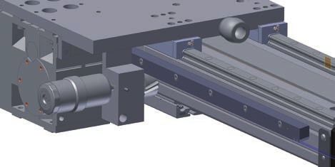
8Drive adaption
Assembly from coupling to linear axes with toothed belt drive
Fastening torque [Nm]
Linear axis
Clamping hub Tension hub
AXC40 1.34 1.34
AXC60 10.5 3
AXC80
10.5 6
AXDL110
AXC100
AXC120
25 6
AXDL160
AXDL240
Drawback bolt
Clamping hub for drives with
feather key
Clamping hub for
connecting shaft
Tension hub for drives with
smooth shaft
Fig. 5
9Motor mounting
Maximum driving torques
Incline and/or Max. driving torque
Item description Driving
feeder constant (Emergency Stop)
according to type label element
[mm/rotation] [Nm] 1)
AXC40Z 75 2.5
AXC60Z 150 13.4
AXC80Z 200 27.7
AXC100Z 264 122
Toothed belt
AXC120Z 320 127
AXDL110Z 175 27.3
AXDL160Z 224 65.2
AXDL240Z 272 216
AXC60A 150 13.4
AXC80A 200 27.7
AXC120A 320 127
AXDL160A 210 65.5
AXDL240A 272 216
AXC40S_1205 5 0,9
AXC40S_1210 10 1.1
AXC60S_1605 5 3.2
AXC60S_1610 10 4.6
AXC60S_1616 16 5.7
AXC80S_2005 5 4.3
AXC80S_2020 20 15
AXC80S_2050 50 30
AXC100S_2505 5 5.2
AXC100S_2510 10 10
AXC100S_2525 25 27
Ball screw drive
AXC120S_3205 5 7.1
AXC120S_3210 10 19
AXC120S_3220 20 27
AXC120S_3232 32 43
AXDL110S_1605 5 3.2
AXDL110S_1610 10 4.6
AXDL110S_1616 16 7.1
AXDL160S_2505 5 3.8
AXDL160S_2510 10 7.6
AXDL160S_2020 20 9.6
AXDL160S_2050 50 38
AXDL240S_3205 5 6.4
AXDL240S_3210 10 15
AXDL240S_3220 20 27
AXDL240S_3232 32 43
10Incline and/or Max. driving torque
Item description Driving
feeder constant (Emergency Stop)
according to type label element
[mm/rotation] [Nm] 1)
AXLT155S_2005 5 4.3
AXLT155S_2020 20 17
AXLT225S_2505 5 5.4
AXLT225S_2510 10 11
Ball screw drive
AXLT225S_2525 25 23
AXLT325S_3205 5 8.0
AXLT325S_3210 10 23
AXLT325S_3220 20 27
AXLT325S_3232 32 43
AXLT455S_4005 5 13
AXLT455S_4010 10 34
AXLT455S_4020 20 50
AXLT455S_4040 40 105
AXC40T_1203 3 0.55
AXC60T_1604 4 1.6
AXC60T_1608 8 3.1
AXC80T_2004 4 2.0
AXC80T_2008 8 4.0
AXC100T_2405 5 4.1
AXC100T_2410 10 8.3
Trapezoidal thread drive
AXC120T_3606 6 10
AXC120T_3612 12 20
AXDL110T_1604 4 1.6
AXDL110T_1608 8 3.1
AXDL160T_2405 5 4.1
AXDL160T_2410 10 8.3
AXDL240T_3606 6 10
AXDL240T_3612 12 20
AXLT155T_2004 4 2.8
AXLT155T_2008 8 5.5
AXLT225T_2405 5 4.1
AXLT225T_2410 10 8.3
AXLT325T_3606 6 10
AXLT325T_3612 12 20
AXLT455T_4007 7 16
AXS120TM280 Gear rack 280 64
AXS120TM500 + 500 233
AXS240TM500 toothed belt 500 233
AXS200M250 250 233
AXS200M200 200 195
Gear rack
AXS230M320 320 547
AXS280M200 200 102
AXS280M400 400 1034
AXS460M250 250 233
AXS280Z Toothed belt 480 306
1)
Maximum motor torque to be set = table value / gear ratio
11Motor mounting to linear axes
with toothed belt drive and clutch housing
Linear axis Mounting dimension TA fastening torque [Nm]
PC Clamping hub Tension hub
31 1.34 -
AXC40-ZK
38 - 1.34
AXC60-_K 50 10.5 3
AXC80-_K 59 10.5 6
AXC120-_K 65 25 6
AXDL110 32.5 10.5 6
AXDL160 22.5 25 6
AXDL240 10 25 6
Elastomer element
Drawback bolt
Clutch housing
Clutch hub
L2: Dimensions s. catalog, linear axis - chapter drive adaption
12Motor mounting to linear axes
with toothed belt drive and planetary gearbox
Linear axis Width across flats Shaft diameter Drawback bolt
[mm] fastening torque [Nm]
AXC40ZP 3 All 5.6
3 bis 14 4.5
1- level
AXC60ZP/AP 4 19 9
3 2- level bis 14 4.5
3 11 4.1
4 1- level 14 9.5
AXDL110ZP 5 19 14
3 11 4.1
2-level
4 14 9.5
4 14 9.5
5 1-level 19 14
AXC80ZP/AP 6 24 35
AXDL160ZP/AP 3 11 4.1
4 2-level 14 9.5
5 19 14
5 19 14
6 1- level 24 35
AXC100ZP 8 24/ 38 79
AXC120ZP/AP
AXDL240ZP/AP 4 14 9.5
5 2- level 19 14
6 24 35
1. Lay linear axis sideways so that the motor mounting flange faces upward
2. Degrease drive shaft, hollow shaft bore and bolt spacer
3. Adjust carriage until the drawback bolt in the access bore becomes visible
4. For AXC60, ensure that the slot in the bolt spacer is turned 90° to the drawback bolt
5. Insert motor
6. For AXC80 + 120 and AXDL160 + 240 with two drawback bolts: manually tighten drawback bolts
applying gentle, even pressure. Tighten drawback bolts with torque key; for two drawback bolts, in
alternating increments.
7. Screw in cap screws
8. Close bore in motor mounting flange with enclosed plugs
Please read the documentation of supplied motor.
Fig. 6
13Motor mounting to linear axes and linear tables
with screw-type drive
Elastomer element drilled Mounting dimension A Drawback bolt fastening
Linear axis
through for motor shaft * [mm] torque [Nm]
AXC40S - 7 1.34
AXC60S
AXC80S
AXC100S
19 3 10.5
AXDL110S
AXDL160S
AXLT225
AXC120S
AXDL240S 24 3 10.5
AXLT325
AXLT155 - 7 1.34
AXLT455 - 8 25
* For motors with feather key, a shorter feather key for replacement will be included with specified shaft diameter
Clutch housing
Intermediate flange (optional)
Clutch hub
Elastomer element
Drawback bolt
Fig. 7
Please note:
A + B = Coupling mounting dimension
Fig. 8
Please read the documentation of supplied motor.
14Motor mounting to belt drive
AXC60 AXC80 AXC100 AXC120
Pitch ball screw [mm] 5 51) 10 16 5 51) 20 50 5 10 25 5 10 101) 20 32
Pretension force
on the display unit [N] 2) 100 140 220 230 100 180 370 625 165 320 450 140 220 405 500 630
Pretension force
[N] 3) 50 70 110 115 50 90 185 313 83 160 225 70 110 203 250 315
at the timing belt
Natural frequenzy [Hz] 3) 149 176 221 226 68 91 130 169 87 121 143 52 65 88 98 110
Torque drawback bolt
(oiled) [Nm] 4) 0,2 0,3 0,5 0,5 0,2 0,4 0,8 1,4 0,4 0,7 1,0 0,4 0,7 1,2 1,5 1,9
Distance force transmission 18 18 18 18 21 21 21 21 21 21 21 30 30 30 30 30
to the motor flange [mm]
Maximum permissible torque 1,2 2,9 4,6 4,9 1,3 4,2 8,8 14,9 3,8 7,6 10,7 5,2 8,2 15,3 19,0 24,1
on the ball screw [Nm] 5)
AXDL110 AXDL160 AXDL240
Pitch ball screw [mm] 5 51) 10 16 5 10 20 25 50 5 10 101) 20 32
Pretension force
[N] 2) 100 140 220 230 165 320 370 450 625 140 220 405 500 630
on the display unit
Pretension force
[N] 3) 50 70 110 115 83 160 185 225 313 70 110 203 250 315
at the timing belt
Natural frequenzy [Hz] 3) 149 176 221 226 87 121 130 143 169 52 65 88 98 110
Torque drawback bolt
[Nm] 4) 0,2 0,3 0,5 0,5 0,4 0,7 0,8 1,0 1,4 0,4 0,7 1,2 1,5 1,9
(oiled)
Distance force transmission 18 18 18 18 21 21 21 21 21 30 30 30 30 30
to the motor flange [mm]
Maximum permissible torque 1,2 2,9 4,6 4,9 3,8 7,6 8,8 10,7 14,9 5,2 8,2 15,3 19,0 24,1
on the ball screw [Nm] 5)
AXLT155 AXLT225 AXLT325 AXLT455
Pitch ball screw [mm] 5 20 5 10 25 5 10 101) 20 32 5 10 20 40
Pretension force
[N] 2) 200 290 165 320 450 140 220 405 500 630 115 380 575 1650
on the display unit
Pretension force
[N] 3) 100 145 83 160 225 70 110 203 250 315 58 190 288 825
at the timing belt
Natural frequenzy [Hz] 3) 159 192 87 121 143 52 65 88 98 110 20 36 44 75
Torque drawback bolt
[Nm] 4) 0,4 0,6 0,4 0,7 1,0 0,4 0,7 1,2 1,5 1,9 0,3 1,1 1,7 4,9
(oiled)
Distance force transmission 18 18 21 21 21 30 30 30 30 30 45 45 45 45
to the motor flange [mm]
Maximum permissible torque 4,2 6,2 3,8 7,6 10,7 5,2 8,2 15,3 19,0 24,1 7,0 24,1 36,6 104,8
on the ball screw [Nm] 5)
1)
XC reinforced mounting (standard with AXDL and AXLT)
A
2)
NTN-SNR toothed belt tensioning device
3)
Frequency meter
4)
Drawback bolt prior to mounting on head and thread lubricated
5)
Max. permissible motor torque = tabular value / ratio
15CAUTION:
Observe permissible motor shaft capacity; reduce pre-load and torque, if necessary.
Allow for 25% safety for pre-load via drawback bolt.
Motor shaft diameter [mm] 6 8 to 14 ex 15
Fastening torque clamp ring [Nm] 2 5 10
Please note:
Drawback bolt must be lubricated prior to mounting.
Motor adapter
mounting screw
Clamping ring Drawback bolt
Fig. 9
Please read the documentation of supplied motor.
16Switches
Circuit diagrams
Mechanical switches or inductive proximity switches are available for position detection depending on
requirements. Professional wiring is possible due to standard two-way distributor and sensor boxes.
Two-way distributor
1st M8 jack 2nd M8 jack
M12
connecter
Contact configuration: 3- pin distributor
Two-way distributor
M12 connecter M8 jack
4-pin 3-pin
Pole diagram
Sensor box with M12 plug connection for 4 or 6 circuit breaker
Rated voltage 32 V DC
Supply voltage 10 V DC ... 30 V DC
Max. carrying capacity per E/A signal 1A
Max. carrying capacity per slot 2A
Max. current sum 3A
Degree of soiling 3
Protection type IP 68
Ambient temperature range -25°C ... 80°C
Contact holder PBT (UL 94 V0)
Contact basis material CuZn, nickel sublayer and
gold-plated
Tapped bushing CuZn, nickel-plated
Flammability class acc. to UL94 V-0
17Maintencance and lubrication
General maintenance and care instructions
All maintenance and service works must be carried out in power off and secured stage.
Caution! The motor housing can reach high temperatures during operation.
Drive systems
The toothed belt does not generally require maintenance work and will be set to the correct tension during
manufacture. Retightening is not necessary during service life with intended use. For servicing the ball screw
drive, please observe the information in the maintenance intervals and lubricant quantities section.
Please note:
In a system that utilises two axes connected with a shaft the toothed belts in both axes should be
replaced.
Guiding systems
Because the rollers in the roller guides are equipped with lifelong lubrication, they do not need to be serviced.
Guiding system is performed during manufacture. Readjustment is unnecessary during service life with
intended use. Roller guide shafts are supplied with oil via lubricating felt located in the carriage. Please
observe the information in the maintenance intervals and lubricant quantities section.
For ball rail system maintenance, please observe the information in the maintenance intervals and lubricant
quantities section.
To ensure long term performance of the linear axis, it is necessary to perform periodic inspects for external
damage and contamination. In harsh ambient conditions with intensified contamination, the inspection
period should be adjusted accordingly to perform necessary cleaning and relubrication. Following longer
periods of linear axis use, it may be necessary to replace brush scrapers and/or sealing strip in the course
of cleaning. Please observe the following mounting instructions.
Brush scraper replacement – AXC series
To take out the brush scraper and replace it with a new one (fig. 10), loosen and remove the screws.
Terms for spare parts orders can be found in the accompanying assembly drawing.
Fig.10
18Sealing strip replacement – AXC series
First loosen and remove the screws (a) in the carriage to remove the slide plate (b). The belt clamping on the
axis ends can then be loosened. With toothed-belt axes, the sealing strip is clamped by the end position
damper (c) and loosened by removing the cap screw (d) (fig. 12). Ball screw drive linear axes feature a belt
clamping through a sheet (e) that can be removed by unscrewing the retaining screws (f) (fig. 11).
The old sealing strip (g) can then be removed and replaced with a new one.
Please always indicate the linear axis serial number when ordering a replacement sealing strip so it
can be cut to the exact length of the respective profile to achieve an optimum sealing.
e
f
g d c
b
a
Fig.11 Fig.12
Prior to mounting the new masking belt, it must be ensured that the pressure roller in the slide plate and the
guide rollers in the carriage section can be slightly turned on the steel pins. The pins should be cleaned or
replaced, if necessary (fig. 13).
Fig.13
19The sealing strip has a trapezoidal cross section. When applying the new sealing strip, it must be ensured
that the broadest surface is on the bottom. Applying gentle pressure by hand or with a smooth object free
of sharp edges, latch the belt into place in the intended slot so that it is flush with the upper profile edge.
Mounting can also be performed in the reverse of disassembly order.
Masking belt replacement – AXDL series
First loosen and remove the belt deflection (b) together with the lubricating nipple (f) and the disc (e).
The attachment rail (d) can then be removed by unscrewing the retaining screws (c). The old masking belt (a)
can now be removed and replaced with a new one.
Mounting can also be performed in the reverse of disassembly order.
Important note: The new sealing strip should be tightened in a way that it does not drag on the table.
This can be checked with inspection bore holes in the slot bottom (sealed with plastic plugs).
c b
d
e
f
a
20Maintenance intervals and lubricant quantities
Linear ball rail system
With various test conditions, it was established that the calculated life span can be achieved with initial
greasing.
Because the lubricant manufacturer does not guarantee a general service life for its products, we recommend
a relubrication interval of 10,000 km of linear travel or once per year.
Longer relubrication intervals are possible after consulting the lubricant manufacturer for a defined application,
if necessary. A petroleum-based lithium soap roller bearing lubricant should be used for relubrication;
otherwise, the compatibility must be reviewed.
Lubricants with a solid lubricant percentage (e.g. graphite or MoS2) may not be used.
Other lubricants can also be specified for special applications (as example food industry).
Because relubrication interval depends on several factors, e.g. degree of soiling, operational temperature,
load, etc., the information stated here should only serve as a guideline.
Roller bearing
We recommend a lubrication interval of 5,000 km or once a year. Oil to be used: ISO- VG460.
Ball screw drive
Standard lubrication requirements for rolling bearings apply for ball screw drives. Lubrication loss is greater
than with conventional rolling bearings due to axial movement between the shaft and the screw nut. Grease-
lubricated ball screw drives have the advantage of only needing relubrication after long travel, meaning that
a relubrication device can be omitted in many cases. The lubrication amount should be measured to ensure
that hollow spaces are approximately halfway filled. All high-quality roller bearing lubricants are suitable for
use. Please observe lubricant manufacturer guidelines!
Lubricants with a solid lubricant percentage (e.g. graphite or MoS2) may not be used.
If you wish to achieve as long of a relubrication interval as possible, greases pursuant to DIN 51825 K2K and
pursuant to DIN 51818 for higher loads KP2K of NLGI class 2 should be favoured
Relubrication intervals for NLGI 2 lubricants:
dnenn Travel (km) with pitch P=
5 10 16 20 25 32 40
≤ 40 mm 250 500 800 1000 1250 1600 2000
Boundary conditions
Load ≤ 0.2 C Nmin = 100 min-1
Tempmax.screwnut = 80° C TempCont.screwnut = 60° C
Because relubrication interval depends on several factors, e.g. degree of soiling, operational temperature,
load, etc., the information stated here should only serve as a guideline.
Trapezoidal thread
Lubrication interval 10 to 20 km.
Lubricant as for linear axis. For AXC, a special lubricant with MoS2, or PTFE may also be used, but these
may not get into the lubrication connection "F" for the linear axis.
21Recommended relubrication quantities [cm3] – AXC series
Linear axes with ball screw drive: lubricating point S
Incline
Axis
S_ _5 S_ _10 S_ _16 S_ _20 S_ _25 S_ _32 S_ _50
AXC40 0.35 0.35
AXC60 0.65 0.9 1.0
AXC80 1.1 2.5 4.6
AXC100 1.6 1.9 3.5
AXC120 2.2 3.1 3.6 5.5
Linear axes with ball screw drive: lubrication point F
Axis B/C
AXC40 0.3
AXC60 1
AXC80 2
AXC100 3
AXC120 4
Linear axes with toothed belt drive generally only have one lubrication point for linear guide lubrication.
Quantities listed in the tables are based on the relubrication amount per lubricating point.
Fig. 14
AXC series linear axes feature lubricating nipples on both sides to achieve the highest possible level of
accessibility. This means that the quantities listed above may only be applied into the respective lubricating
nipple on one side of the axis per lubrication interval.
22Recommended relubrication quantities [cm3] – AXDL series
Linear axes with toothed belt drive: both lubricating points
Linear axes with ball screw drive: lubricating point F
Axis B/C
AXDL110 0.6
AXDL160 1.6
AXDL240 3
Linear axes with ball screw drive: lubricating point S
Incline
Axis
S_ _5 S_ _10 S_ _16 S_ _20 S_ _32 S_ _50
AXDL110 2.25 2.5 2.6
AXDL160 4.0 4.3 4.9 7.0
AXDL240 8.2 9.1 9.6 11.5
Quantities listed in the tables are based on the relubrication quantity per lubricating point.
Fig.15
Linear axes from the AXDL series feature lubricating nipples on both front sides of the table to achieve the
highest possible level of accessibility. This means that the quantities listed above may only be applied into
the respective lubricating nipple on one side of the axis per lubrication interval.
23Recommended relubrication quantities [cm3] – AXLT series
Incline
Axis
S_ _5 S_ _10 S_ _20 S_ _25 S_ _32 S_ _40 S_ _50
AXLT155 1.1 2.5 4.6
AXLT225 1.6 1.9 3.5
AXLT325 2.2 3.1 3.6 5.5
AXLT455 3.0 6.7 8.7 14.3
Note: he capacity of a standard grease gun conform to DIN1283
T
(with 400 g cartridges) is 2 cm3 per stroke.
Ball screw drive relubrication point
24Lubrication instructions for NTN-SNR linear guide (four lubrication points)
Axis B/C B
AXLT155 0.6 -
AXLT225 1.2 -
AXLT325 3 -
AXLT455 - 3.4
First loosen the cap screws (a) and push back the bellows (b).
b
a
Each carriage is individually lubricated via lubricating nipples (4 pcs.) accessible at this point.
25Recommended relubrication quantities [cm3] – AXS series
Axis B/C
AXS200M200 3.0
AXS200M250 3.0
AXS230M320 3.0
AXS280M400 3.4
AXS280Z 3.4
AXS280M200 3.4
AXS460M250 3.4
AXS120T Slide plate lubrication point 7.6 7.6
AXS120T Basic axis 2.0 2.0
AXS240TM500 1. Axis level 3.0 3.0
AXS240TM500 2. Axis level 4.0 4.0
Quantities listed in the tables are based on relubrication quantities per carriage. Lubrication takes place directly
via the lubrication nipple of the carriage.
Only the carriages in the second telescopic axis guide level are supplied via the lubrication point in the slide plate.
Only for initial lubrication First axis level: 4 lubrication points
Second axis level:
2 lubrication points,
only lubricate on one side!
Permanent lubrication system
Commissioning: use a screwdriver to set the rotating
switch to "ON", also see description on page 29.
Recommended oiling relubrication quantity [cm3] for roller guides:
Axis type Relubrication amount [cm3] Factor
AXC40 0.4 3
AXC60 0.4 5
AXC80 2.0 2
AXC120 2.0 3
AXDL110 1.0 3
AXDL160 1.5 4
AXDL240 2.8 5
26AXC linear axes feature lubricating nipples on both sides to guarantee the highest possible level of
accessibility. AXDL linear axes feature lubricating nipples on both front sides of the table. This means that
the quantities listed above may only be applied into the respective lubricating nipple on one side of the axis
per lubrication interval.
Relubrication option for linear axes with toothed belt drive. Lubrication point F for axis type AXC120 with ball
screw drive and roller guide.
The given factor is to be applied as follows:
AXC series: For incline mounting position and initial relubrication overhead mounting.
AXDL series: For overhead and incline mounting position for initial relubrication.
We recommend a relubrication interval of 5,000 km or once per year.
Oil to use: ISO- VG 460.
Lubricants for screw drive and/or profiled rail bearings
The NTN-SNR lubricant LUB HEAVY DUTY is used under normal conditions. Special requirements and
unusual environmental conditions require the use of a suitable lubricant. When relubricating with other
lubricants, the compatibility of the lubricants is to be tested.
Description Type of oil, NLGI Walk Basic oil Density Temperature Properties Applications
Consistency class penetration viscosity [kg/m2] range
builder DIN DIN ISO DIN51562 [°C]
51818 2137 at at 40°C
25°C [mm2/s]
[0,1 mm]
Mineral oil, 2 150 900 -30…+110 Normal conditions, General machine
High-pressure standard construction
additive lithium soap lubrication
LUB HEAVY
DUTY GREASE
Paraffin mineral oil / 2 265… 295 ca. 240 920 -30…+110 Good corrosion Food
aluminium - protection, very industry
LUB complex soap good adhesion,
FOOD GREASE high water-
resistance, NSF
H1-registered*
Synthetic 2 265… 295 ca. 30 890 -30…+140 Specially Clean room
hydrocarbons - pressure-resistant, applications
Klübersynth Oil / special - good wearing
BEM34-32 calcium soap protection, good
ageing resistance,
low starting torque
Synthetic 1 310… 340 ca. 150 920 -45…+120 Good corrosion Pharmaceutical
hydrocarbons - oil / protection, industry / food
Klübersynth ester oil / aluminium - age-resistant, industry
UH1 14-151 complex soap water-resistant,
NSF H1-
registered*
* This lubricant has been registered as a H1 product, i.e. it was developed for occasional, technically unavoidable contact
with food. Experience has shown that the lubricant can also be used for corresponding applications in the pharmaceutical
and cosmetics industry under the conditions as specified in the product information. However, there are no specific test
results, e.g. with regard to bio-compatibility, as may be required for pharmaceutical applications. Thus corresponding risk
analyses in this field are to be carried out by the plant manufacturer and operator before application. Where necessary,
steps are to be taken to exclude any risks to health or injuries. (Source: Klüber Lubrication)
27Lubricants for roller bearings
The tempered steel shafts of the roller bearings are usually lubricated with Shell Omala 460.
Kinematic
Temperature
viscosity DIN51562 Density
Description Type of oil range Properties Application range
at 40°C [g/cm3]
[°C]
[mm2/s]
Good ageing and Good ageing and
temperature stability, temperature stability,
good corrosion good corrosion
Shell Omala Mineral oils and
460 904 -10…+90°C protection properties protection properties
460 additives.
General machine
construction
Good ageing and wear Pharmaceutical
Klüberoil 4 protection, NSF H1 industry, food industry
Polyalphaolefin film 460 860 -30…+120°C registered*
UH1-460N
Automatic lubricant dispenser
Automatic lubrication will ensure the permanent and regular lubrication of the bearing and driving elements
of the linear axes. The lubrication process can be optimised with the aid of the automatic lubricant dispenser,
without making changes to your system. The lubricant dispensers are connected to the lubrication connection
of the linear axis. It should be taken into account that every lubrication point requires a separate lubricant
dispenser. The lubrication dispensers can be provided with various lubrication or oil types. SNR offers
various types of lubricant dispensers.
Our SNR application engineers are available to answer any further questions you might have.
Central lubrication connection
SNR linear axes can be supplied with a connection for a central lubrication system on request. Our SNR
application engineers are available to answer any further questions you might have.
28Lubricating the gear racks
The gear rack drive is optimally supplied with lubricant, using a permanent lubrication system in combination
with a felt cog wheel. The system has been filled with the lubricant UNIVERSAL+. An emptying time of 12
months has been pre-set at the factory. This should be adjusted to an emptying time of 6 months if the
operating time specified in the table has been exceeded in any given year. After this time, the lubricant tank
and the battery must be exchanged. Order description: LUBER DRIVE REFILL 120 UNIVERSAL+. Systems
connected to the machine controls, other lubricants or container volumes can also be used as special
equipment. In this case you should order the lubricant tank from the catalogue or stating the serial number
and battery set (not required for externally controlled systems).
Axis Modul km / 120 cm³
AXS120TM280 2 80000
AXS120TM500 3 64000
AXS155TM400 2 80000
AXS240TM500 3 64000
AXS280M200 2 40000
AXS200M200 3 32000
AXS200M250 3 32000
AXS460M250 3 32000
AXS230M320 4 29000
AXS280M400 5 24000
Setting the driving system
The permanent lubrication system is delivered in a switched-off state. Before starting permanent operation,
the system is to be commissioned in accordance with the following description:
Function display
The DRIVE BOOSTER has been equipped with a red and a green LED. The LEDs on the control board may
be viewed through the transparent cover (see Fig. 1). These LEDs inform the operator about the following
operating states and/or faults:
LED Signal Signal duration Operating state
green flashing every 15 seconds Operation (OK)
red flashing every 8 seconds Fault / interrupt
green and red flashing every 3 seconds LC unit empty
red intermittent continuous DRIVE BOOSTER dispensing
Setting options
Setting the operating time
The control board has a quad switch for coding.
Switches 1+2 with the description "TIME" can be used to set
the operating time until the LC unit is emptied, while Switches
3 + 4 with the description "VOL" are used to adjust the size of
the LC unit.
29Setting the 1+2 "TIME" switch
A small screwdriver or the fingers may be used to set or adjust
the switches.
The operating time to emptying that has been set can be indicated
on the operating system, using the adhesive dots included. The
adhesive dots come in different colours and the operating time in months is printed on them.
Setting of 1+2 "TIME" switches of the quad switch for coding the four different operating times
Setting the 3+4 "VOL" switch
A small screwdriver or the fingers may be used to set or adjust the switches.
Where the position of the 3+4 "VOL" switch of the quad switch for coding does not
correspond to the size of the LC unit, this will result in a wrong signal being sent and in
over- or under-lubrication.
Setting of the 3+4 "VOL" switch of the quad switch for coding the two sizes of the LC unit
Switching on the lubricant dispenser
To switch on the lubricant dispenser, set the rotating switch on the cover of
the driving system (Fig. 16) from the "OFF" position to the "ON" position,
using a screwdriver. This will immediately start a dispensing process. To
switch off the lubricant dispenser, change the setting from "ON" to "OFF".
Fig.16
Changing the settings
The operating time and the size of the LC unit can only be adjusted when a new LC unit is being used.
Where the settings have been changed during operation and/or after commissioning, a new, fully filled LC
unit and a new set of batteries needs to be used.
If the settings are changed during operation, this will result in a fault in the controls and the electronic
monitoring system. Thus NTN-SNR cannot accept any liability for precise lubrication.
Each time the settings have been changed, use a new, fully filled LC unit and a new set of batteries.
Never use an LC unit that is already partially empty!
30Produktübersicht
Kompaktprogramm mit den Baureihen AXC, AXDL, AXLT
Type Profilquerschnitt Antriebselement Profilschienenführung Laufrollenführung
[mm]
AXC40Z 40 x 40 •
AXC60Z 60 x 60 • •
AXC80Z 80 x 80 • •
AXC100Z 100x100 • •
AXC120Z 120 x 120 • •
Zahnriemen
AXDL110Z 110 x 50 • •
AXDL160Z 160 x 66 • •
AXDL240Z 240 x 100 • •
AXC60A 60 x 60 • •
AXC80A 80 x 80 • •
AXC120A 120 x 120 •
AXDL160A 160 x 66 • •
AXDL240A 240 x 100 • •
AXC40S 40 x 40 •
AXC60S 60 x 60 • •
AXC80S 80 x 80 •
Kugelgewindetrieb
AXC100S 100x100 •
AXC120S 120 x 120 • •
AXDL110S 110 x 50 •
AXDL160S 160 x 66 •
AXDL240S 240 x 100 •
AXLT155 155 x 33 •
AXLT225 225 x 40 •
AXLT325 325 x 50 •
AXLT455 455 x 70 •
AXC40T 40 x 40 •
AXC60T 60 x 60 • •
AXC80T 80 x 80 • •
AXC100T 100x100 • •
Trapezgewinde
AXC120T 120 x 120 • •
AXDL110T 110 x 50 •
AXDL160T 160 x 66 •
AXDL240T 240 x 100 •
AXLT155T 155 x 33 •
AXLT225T 225 x 40 •
AXLT325T 325 x 50 •
AXLT455T 455 x 70 •
NTN-SNR- Kompaktachsen der Baureihen AXC, AXDL und AXLT sind in verschiedenen Baugrößen sowie mit
variablem Antriebs- und Führungssystem erhältlich. Sie werden vorwiegend einbaufertig montiert geliefert.
Die genauen Daten und Abmaße, finden Sie im Katalog SNR-Linearachsen.
31Systemprogramm mit der Baureihe AXS
Type Profilquerschnitt Antriebselement Vorschubkonst.
[mm] [mm/Umdr.]
Zahnriemen 500
AXS120T 120 x 120
280
Zahnstange
Zahnriemen
AXS240T 240 x 100 500
Zahnstange
250
AXS200M 200 x 100
200
AXS230M 230 x 160 320
Zahnstange 400
AXS280M 280 x 170
200
AXS460M 400 x 300 250
AXS280Z 280 x 170 Zahnriemen 480
NTN-SNR- Systemachsen der Baureihe AXS sind in verschiedenen Baugrößen und mit variablem
Antriebssystem erhältlich. Das Führungssystem besteht immer aus Profilschienenführungen. Weiterhin
steht mit der Baureihe AXS120T und AXS240T eine Teleskopachse für vertikalen und horizontalen Einsatz
zur Verfügung. Die Linearachsen werden vorwiegend einbaufertig montiert geliefert.
Die genauen Daten und Abmaße, finden Sie im Katalog SNR-Linearachsen.
32Sicherheit
Allgemeine Sicherheitshinweise
Das Gerät ist dem heutigen Stand der Technik und den geltenden Vorschriften entsprechend gebaut.
Das Gerät entspricht der EU-Richtlinie Maschinen, den harmonisierten Normen, Europanormen oder den
entsprechenden nationalen Normen. Dies wird durch eine Herstellererklärung bestätigt.
Es gelten selbstverständlich einschlägige Unfallverhütungsvorschriften, allgemein anerkannte
sicherheitstechnische Regeln, EU-Richtlinien, sonstige zutreffende Normen und länderspezifische
Bestimmungen. Da die Lineareinheiten in den unterschiedlichsten Bereichen eingesetzt werden können,
geht die Verantwortlichkeit der spezifischen Anwendung mit dem Einsatz auf den Anwender über.
Von diesem Gerät gehen unvermeidbare Restgefahren für Personen und Sachwerte aus. Deshalb muss jede
an diesem Gerät arbeitende Person, die mit dem Transport, Aufstellen, Bedienen, Warten und Reparieren des
Gerätes zu tun hat, eingewiesen sein und die möglichen Gefahren kennen. Dazu muss die Betriebsanleitung
verstanden und beachtet werden.
Weiterführend bestehen im Bereich der Antriebselemente Verletzungsgefahren durch rotierende oder
andersartig bewegte Bauteile. Bei in Betrieb befindlicher Linearachse besteht insbesondere im Bereich
der Endlagendämpfer und der Endschalter erhöhte Quetschgefahr durch den bewegten Schlitten.
Auf diese Restgefahren hat der Anwender durch Schilder oder schriftliche Verhaltensregeln hinzuweisen.
Alternativ kann der Anwender diese Restgefahren durch geeignete konstruktive Maßnahmen beseitigen
oder weitestgehend ausschließen. Bei hohen Geschwindigkeiten, besonderen Applikationen und ggf. bei
Aufsummierung mehrerer Geräuschquellen kann sich der Geräuschpegel erhöhen. Der Anwender muss
entsprechende Schutzmassnahmen treffen.
Die Inbetriebnahme der Lineareinheiten ist solange untersagt, bis sichergestellt wurde, dass die Maschine
oder Anlage, in die sie eingebaut worden sind, den Bestimmungen der EU-Richtlinie Maschinen, den
harmonisierten Normen, Europanormen oder den entsprechenden nationalen Normen entspricht.
Bestimmungsgemäße Verwendung
Grundsätzlich sind SNR-Linearachsen und SNR-Lineartische für lineare Bewegung, wie sie beim
Positionieren, Takten, Transportieren, Palettieren, Beladen, Entladen, Klemmen, Spannen, Prüfen, Messen,
Hantieren und Manipulieren von Werkstücken oder Werkzeugen vorkommen, vorgesehen. Hierbei sind die
typenspezifischen Belastungsdaten aus den jeweiligen Katalogunterlagen bzw. ergänzenden technischen
Berechnungen aus unserem Hause zu berücksichtigen. Weiterhin ist eine Betriebstemperatur von –10° C bis
+40° C einzuhalten.
Eine andere oder darüber hinausgehende Verwendung gilt als nicht bestimmungsgemäß. Für hieraus
resultierende Schäden haftet der Hersteller nicht. Das Risiko trägt allein der Anwender.
Die Linearachse darf nur von Personen betrieben und gewartet werden, die hiermit vertraut und über die
Gefahren unterrichtet sind.
In besonderen Anwendungsfällen (z.B. Lebensmittelindustrie, Reinraum usw.) können besondere
Vorkehrungen getroffen werden, die von den Standardausführungen abweichen.
33Transport und Lagerung
Vorkehrungen bei Transport und Lagerung
SNR- Linearachsen sind hoch präzise Geräte. Heftige Stöße können die Mechanik der Linearachsen
beschädigen und ihre Funktion beeinträchtigen. Um Schäden bei Transport und Lagerung zu vermeiden,
sind folgende Punkte zu beachten:
• Schutz vor starken Erschütterungen bzw. Stößen, aggressiven Medien, Feuchtigkeit und Schmutz
• Beim Transport in ausreichend großer Verpackung unterbringen und gegen Verrutschen sichern.
Montageanleitung und Inbetriebnahme
Bei der Montage der Linearachse (unvollständigen Maschine) müssen unten aufgeführte Bedingungen erfüllt
sein, damit sie ordnungsgemäß und ohne Beeinträchtigung der Sicherheit und Gesundheit des Personals
mit anderen Teilen zu einer vollständigen Maschine zusammengebaut werden kann.
Montage und Befestigung der Linearachsen
Achtung! Das Motorgehäuse kann im Betrieb hohe Temperaturen erreichen.
Die Linearachse ist so anzubringen, dass eine Körperschallübertragung minimiert wird. Weitere Maschinenteile
sollten so ausgelegt werden, dass sie nicht im Resonanzbereich der Linearachse liegen.
SNR- Linearachsen der Baureihe AXC und AXDL können durch Nutensteine oder Befestigungsleisten auf
ebenen Flächen oder anderen Linearachsen aus dem SNR-Programm befestigt werden. Die Anzahl der
Befestigungspunkte muss auf die Anwendung abgestimmt werden. Bei punktueller Auflage der Linearachse
ist darauf zu achten, dass die entstehende Durchbiegung weder die Funktion noch die geforderte Genauigkeit
beeinträchtigt. Die Befestigungsleisten werden seitlich am Linearachsprofil eingehakt und ermöglichen
dank ihrer speziellen Formgebung eine einfache Montage durch eine Verschraubung von oben (Bild 1u. 2).
Sie können innerhalb der gesamten Profillänge frei positioniert werden. Alternativ können alle Linearachsen
auch über einschwenkbare Nutensteine befestigt werden, die ebenfalls über die gesamte Länge frei
positioniert werden können (Bild 3).
Bild.1
Bild 2 Bild.3
34Für die Lineartische der Baureihe AXLT stehen ebenfalls zwei Befestigungsmöglichkeiten zur Verfügung.
Entweder durch eine direkte Verschraubung von oben oder über einschwenkbare Nutensteine von der
Tischunterseite. Diese können über die gesamte Länge frei positioniert werden (Bild 4).
Senkbohrung zur
Verschraubung von
oben
Profilnut zum
Einschieben von
Nutensteinen
Bild 4
Linearachsen der Baureihe AXS ckönnen ebenfalls mittels Nutensteinen und außerdem durch
Adapterplatten (evtl. individuelle Anfertigung) auf ebenen Flächen oder anderen Linearachsen aus dem
SNR-Programm befestigt werden.
Grundsätzlich ist bei allen Befestigungsarten die Anzahl der Befestigungspunkte auf die Anwendung
abzustimmen. Bei punktueller Auflage ist darauf zu achten, dass die entstehende Durchbiegung weder die
Funktion noch die geforderte Genauigkeit beeinträchtigt.
Hinweise zur Inbetriebnahme der Linearachse
Linearachsen können schnelle Bewegungen mit großer Kraft erzeugen. Anbauten an den Schlitten können
bei Kollision zu Personen- oder Sachschäden führen. Deshalb sollte bei der Inbetriebnahme mit größter
Vorsicht vorgegangen werden.
Weiterhin ist bei der Inbetriebnahme darauf zu achten, dass die zulässigen Belastungen nicht überschritten
werden und die Anbauten am Schlitten sicher befestigt sind. Es ist ebenfalls darauf zu achten, dass die
maximal möglichen Verfahrwege nicht überschritten werden. Wird der Verfahrweg über Endschalter begrenzt,
sollten diese vorher auf Funktion und korrekte Position geprüft werden.
Bei Vertikalachsen bestehen Gefahren durch ungewolltes Herabsinken, dagegen muss der Anwender
entsprechende Vorkehrungen treffen. Wir empfehlen FA-Infoblatt Nr. 005 „Schwerkraftbelastete Achsen
(Vertikalachsen)“ Ausgabe 02/2004 vom Fachausschuss Maschinenbau, Fertigungssysteme, Stahlbau
anzuwenden.
Für Schäden, die aus einer Nichtbeachtung dieser Inbetriebnahmehinweise resultieren, haftet
der Hersteller nicht. Das Risiko trägt allein der Anwender.
35Antriebsadaption
ntage von Kupplungen an Linearachsen mit Zahnriementrieb
Anzugsmoment [Nm]
Linearachse
Klemmnabe Tension hub
AXC40 1.34 1.34
AXC60 10.5 3
AXC80
10.5 6
AXDL110
AXC100
AXC120
25 6
AXDL160
AXDL240
Bild 5
36Motormontage
Maximale Antriebsmomente
Steigung bzw. max. Antriebsmoment
Artikelbezeichnung nach
Antriebselement Vorschubkonstante (Not-Aus)
Typenschild
[mm/Umdr.] [Nm] 1)
AXC40Z 75 2.5
AXC60Z 150 13.4
AXC80Z 200 27.7
AXC100Z 264 122
AXC120Z 320 127
Zahnriemen
AXDL110Z 175 27.3
AXDL160Z 224 65.2
AXDL240Z 272 216
AXC60A 150 13.4
AXC80A 200 27.7
AXC120A 320 127
AXDL160A 210 65.5
AXDL240A 272 216
AXC40S_1205 5 0,9
AXC40S_1210 10 1.1
AXC60S_1605 5 3.2
AXC60S_1610 10 4.6
AXC60S_1616 16 5.7
AXC80S_2005 5 4.3
AXC80S_2020 20 15
AXC80S_2050 50 30
AXC100S_2505 5 5.2
AXC100S_2510 10 10
Kugelgewindetrieb
AXC100S_2525 25 27
AXC120S_3205 5 7.1
AXC120S_3210 10 19
AXC120S_3220 20 27
AXC120S_3232 32 43
AXDL110S_1605 5 3.2
AXDL110S_1610 10 4.6
AXDL110S_1616 16 7.1
AXDL160S_2505 5 3.8
AXDL160S_2510 10 7.6
AXDL160S_2020 20 9.6
AXDL160S_2050 50 38
AXDL240S_3205 5 6.4
AXDL240S_3210 10 15
AXDL240S_3220 20 27
AXDL240S_3232 32 43
37Steigung bzw. max. Antriebsmoment
Artikelbezeichnung nach
Antriebselement Vorschubkonstante (Not-Aus)
Typenschild
[mm/Umdr.] [Nm] 1)
AXLT155S_2005 5 4.3
AXLT155S_2020 20 17
AXLT225S_2505 5 5.4
AXLT225S_2510 10 11
Kugelgewindetrieb
AXLT225S_2525 25 23
AXLT325S_3205 5 8.0
AXLT325S_3210 10 23
AXLT325S_3220 20 27
AXLT325S_3232 32 43
AXLT455S_4005 5 13
AXLT455S_4010 10 34
AXLT455S_4020 20 50
AXLT455S_4040 40 105
AXC40T_1203 3 0.55
AXC60T_1604 4 1.6
AXC60T_1608 8 3.1
AXC80T_2004 4 2.0
AXC80T_2008 8 4.0
AXC100T_2405 5 4.1
AXC100T_2410 10 8.3
AXC120T_3606 6 10
Trapezgewindetrieb
AXC120T_3612 12 20
AXDL110T_1604 4 1.6
AXDL110T_1608 8 3.1
AXDL160T_2405 5 4.1
AXDL160T_2410 10 8.3
AXDL240T_3606 6 10
AXDL240T_3612 12 20
AXLT155T_2004 4 2.8
AXLT155T_2008 8 5.5
AXLT225T_2405 5 4.1
AXLT225T_2410 10 8.3
AXLT325T_3606 6 10
AXLT325T_3612 12 20
AXLT455T_4007 7 16
AXS120TM280 Zahnstange 280 64
AXS120TM500 + 500 233
AXS240TM500 Zahnriemen 500 233
AXS200M250 250 233
Zahnstange
AXS200M200 200 195
AXS230M320 320 547
AXS280M200 200 102
AXS280M400 400 1034
AXS460M250 250 233
AXS280Z Zahnriemen 480 306
1)
Einzustellendes Motormaximalmoment = Tabellenwert / Getriebeübersetzung
38You can also read