POE PRO USER GUIDE PROOF OF PERFORMANCE
←
→
Page content transcription
If your browser does not render page correctly, please read the page content below
PoE Pro
User Guide
        Proof of Performance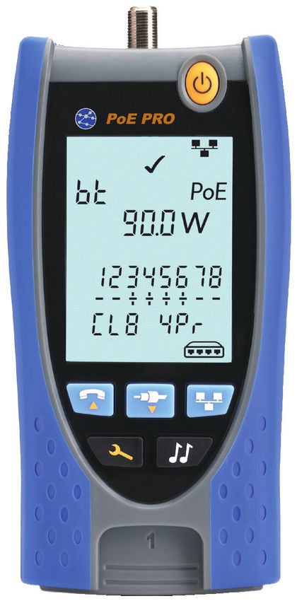
PoE Pro

    User Guide

    Guide d’utilisation

    Bedienungsanleitung

    Guida utente

    Manual de usuario

    Guia do Usuario

    158823.01 (05/2019)

    IDEAL INDUSTRIES Networks Ltd.
    Stokenchurch House
    Oxford Road
    Stokenchurch
    High Wycombe
    Buckinghamshire
    HP14 3SX
    United Kingdom

2                                PoE PRO   158823.01
© IDEAL INDUSTRIES Networks Ltd 2019
The information contained in this document is the property of IDEAL INDUSTRIES Networks Ltd. and is supplied without
liability for errors and omissions. No part of this document may be reproduced or used except as authorized by contract
or other written permission from IDEAL INDUSTRIES Networks Ltd. The copyright and all restrictions on reproduction
and use apply to all media in which this information may be placed. IDEAL INDUSTRIES Networks Ltd. pursues a policy of
continual product improvement and reserves the right to alter without notice the specification, design, price or conditions
English
of supply of any product or service. All rights reserved.
Les informations dans ce document sont la propriété de IDEAL INDUSTRIES Networks Ltd. et elles sont fournies sans
responsabilité pour les erreurs et les omissions. Aucune partie de ce document ne doit être reproduite ou utilisée, sauf
en cas d’autorisation par contrat ou en cas d’autre autorisation écrite donnée par IDEAL INDUSTRIES Networks Ltd. Le
copyright et toutes les limitations concernant la reproduction et l’utilisation s’appliquent à tous les supports sur lesquels
cette information peut être placée. IDEAL INDUSTRIES Networks Ltd. améliore continuellement ses produits et se réserve Français
le droit de modifier sans préavis la spécification, la conception, le prix ou les conditions de fourniture d’un produit ou d’un
service. Tous droits réservés.
Die Informationen in diesem Dokument sind das Eigentum von IDEAL INDUSTRIES Networks Ltd. und werden ohne
Gewährleistung der Vollständigkeit oder Korrektheit gegeben. Dieses Dokument darf nur soweit vertraglich oder
anderweitig schriftlich von IDEAL INDUSTRIES Networks Ltd. Zugesichert ganz oder teilweise vervielfältigt werden.
Das Urheberrecht und alle Einschränkungen zur Vervielfältigung und Nutzung gelten für alle Datenträger, auf denen
diese Informationen gespeichert werden können. IDEAL INDUSTRIES Networks Ltd. bemüht sich um ständige
Produktverbesserungen und behält sich das Recht vor, die Spezifikation, das Design, den Preis oder die Lieferbedingungen Deutsch
jeglicher Produkte oder Dienste ohne Vorankündigung zu ändern. Alle Rechte vorbehalten.
Le informazioni contenute nel presente documento sono di proprietà di IDEAL INDUSTRIES Networks Ltd. e sono fornite
senza alcuna responsabilità relativa a errori e omissioni. Sono vietati la riproduzione o l’uso di tutto il documento o parte
di esso, salvo se autorizzati da contratto o permesso scritto di IDEAL INDUSTRIES Networks Ltd. Il copyright e tutte
le limitazioni sulla riproduzione e l’uso si applicano a tutti i supporti nei quali le presenti informazioni possono essere
contenute. IDEAL INDUSTRIES Networks Ltd. segue una politica volta al miglioramento continuo dei prodotti e si riserva il
diritto di modificare senza preavviso le specifiche, il disegno, il prezzo o le condizioni di fornitura di qualsivoglia prodotto o Italiano
servizio. Tutti i diritti riservati.
La información que figura en este documento es propiedad de IDEAL INDUSTRIES Networks Ltd., quien no asume
responsabilidad alguna sobre posibles errores u omisiones que puedan existir en este documento. Queda prohibida
la reproducción parcial o total de este documento, así como darle un uso distinto al autorizado mediante contrato o
autorización escrita por parte de IDEAL INDUSTRIES Networks Ltd. independientemente del formato y soporte de los
contenidos. IDEAL INDUSTRIES Networks Ltd. sigue una política de mejora continua del producto y nos reservamos
el derecho de modificar sin previo aviso las especificaciones, diseño, precio o condiciones de suministro de cualquier
Español
producto o servicio. Todos los derechos reservados.
As informações contidas neste documento são de propriedade de IDEAL INDUSTRIES Networks Ltd. e são fornecidas
sem responsabilidade sobre erros e omissões. Nenhuma porção deste documento pode ser reproduzida ou usada exceto
quando autorizada mediante contrato ou outra permissão por escrito da IDEAL INDUSTRIES Networks Ltd. Os direitos de
cópia e restrições de reprodução e uso são aplicáveis a todas as mídias nas quais estas informações possam ser colocadas.
A IDEAL INDUSTRIES Networks Ltd. segue uma política de melhora contínua do produto e se reserva ao direito de alterar
sem aviso prévio as especificações, design, preço ou condições de fornecimento de qualquer produto ou serviço. Todos os
Português
Direitos Reservados.
158823.01 PoE PRO 3WARNING!
! Do not attach to AC power or telecoms cables carrying >60volts. The PoE Pro
Tester may be damaged and cause a safety hazard to the user.
CAUTION!
! Improperly crimped, damaged or un-crimped plugs can damage the ports on
EN the PoE PRO Tester. Inspect plugs for proper termination and crimping before
inserting into the tester. Contacts should always be recessed into the plastic
grooves of the plug. Only use 8-Position plugs with the 8-Pin (DATA) port and
6-Position plugs with the 6-Pin (VOICE) port.
VIDEO
(F-Coax) port
VOICE (6 Pin RJ) DATA (8 Pin RJ) port
port
ON/OFF button
Display
VIDEO port
selection ( ) button
VOICE port selection
( ) button DATA port selection
button
TOOLS button TONE button
Dual Port Remote
Unit
Dual Port Remote Dual Port Remote
Unit VOICE port Unit DATA port
Storage for Coax
Remote Unit
4 PoE PRO 158823.01POWER
To remove / insert the battery:
• Remove the battery cover screw and the
battery cover from the back of the tester.
Battery
• Remove / insert the battery, taking care to cover screw
connect correctly and not to trap the cable. EN
• Replace the battery cover and screw.
To switch the tester ON:
Press the ON/OFF button. Battery
cover
• The display shows the selected port
(VOICE, VIDEO or DATA).
• If the Battery Low Indicator is shown, the
battery should be replaced with a new 9V
battery.
VOICE VIDEO DATA port Setting Backlight Battery
port port selected Indicator Indicator Low
selected selected Indicator
To control the backlight:
• Press the TOOLS button repeatedly until the Backlight Indicator
flashes and the backlight timeout (seconds) is shown.
• Press or to adjust the backlight timeout.
• If zero, the display shows . The backlight will not come on.
• If non-zero, the display shows . The backlight will come on
whenever any button is pressed and after the timeout will first be
dimmed and then go off to maximise battery life.
• Press the TOOLS button repeatedly until the Setting Indicator
disappears.
To switch the tester OFF:
• Press the ON/OFF button.
158823.01 PoE PRO 5TERMINATIONS
The Dual Port Remote Unit can be stored in the bottom end of
the Tester, with the jacks either inside for protection or outside
for testing patch cables without removing it from the Tester,
and provides internal storage for the Coax Remote Unit.
EN
Dual Port Coax RJ45 RJ45
Remote Unit Remote Unit Remote Unit Identifier
# 1 (Standard) # 1 (Standard) # 1 to 12 (Optional - 158050) # 1 to 24 (Optional - 158051)
# 1 to 12 (Optional - 158053)
CONNECTIONS
To connect to a cable and to confirm correct connection: Termination
Number
• Use the correct port (VOICE, VIDEO or DATA) according to
Identifier
the cable connector type. (Use VOICE for RJ11, RJ12, RJ14 Indicator
or RJ25 cables, VIDEO for F 75 Ω Coax or DATA for RJ45).
• Press the corresponding port button (VOICE, VIDEO or
DATA).
• The display shows the selected port.
• Connect one end of the cable to the selected port on
the tester and the other end to a Remote Unit for cable
identification and testing or to an Identifier for cable Remote Unit
identification only. Indicator
• The display shows the type of termination (Remote Unit
or Identifier) and its Number to assist identification when a
number of different terminations are in use.
6 PoE PRO 158823.01PoE TESTING
To test PoE:
• Turn on the PoE PRO tester
• Connect the RJ45 port of the tester to the PoE port or cable to be tested.
EN
• Press the Network button
PoE Detected
Unloaded
Voltage
(Voltage detected
when drawing
no power)
Above screen is displayed when PoE is detected without an ethernet signal (PoE Injector with
input from a switch). It will be shown for two seconds.
Max
Ethernet
Speed
If ethernet is detected, the maximum detected link speed will be shown with the no-load PoE
voltage for two seconds.
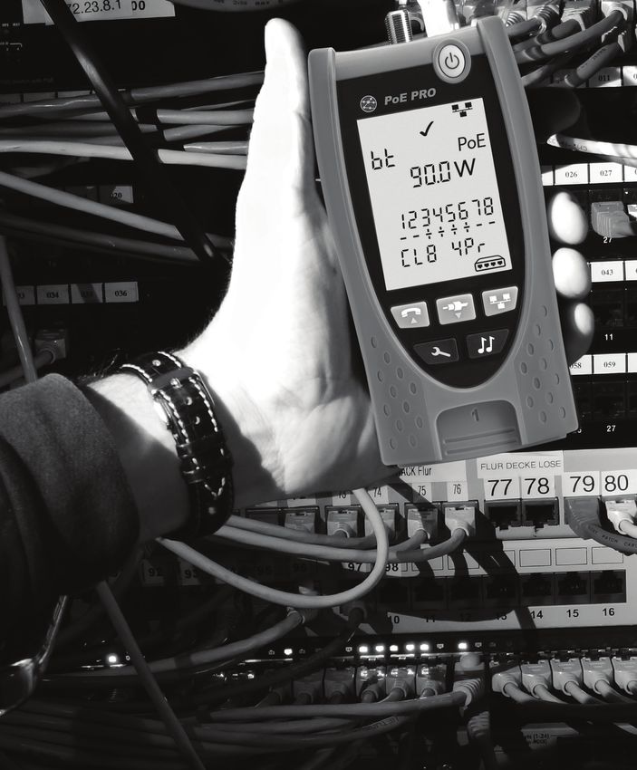
158823.01 PoE PRO 7After PoE detection is confirmed the PoE PRO will begin the test to classify the PSE. This
process will take up to 10 seconds.
EN Pass/Fail
Type(af/at/bt)
PoE Detected
Maximum Power
Available (Voltage
displayed while test
is in progress)
Pin and Polarity
PSE Class Number of pairs
supplying PoE
(2Pr or 4Pr)
Method of Operation
The PoE PRO operates by detecting “pulses” The initial test measures the voltage supplied
from a PoE power supply Power Source by the PSE with no load. This voltage should
Equipment (PSE). These pulses advertise the be 48V or greater when connected directly
PSE’s Class which determines the maximum to the PSE.
amount of power it can supply.
When testing for maximum available power,
The PoE PRO configures itself to the same the PoE PRO will apply a variable load to
Class as the PSE, simulating a powered the cable while measuring the voltage and
device (PD), and demands the maximum current delivered by the PSE.
power that should be available for the
The voltage and current measurements are
advertised Class.
used to calculate power (watts).
8 PoE PRO 158823.01Understanding the Results
Volts Pass / Fail Indication
Voltage displayed on the results screen is the The test will pass ( ) if the power available
“loaded” voltage. It is the voltage measured during the PoE load test is equal to, or
when the PoE PRO applies a load to the greater than the MINIMUM power for
cable, simulating a PoE device (PD). PSE Class.
EN
This voltage may be lower than the unloaded Example: If class 4 is detected the test will
voltage displayed when initially connected. PASS if 25.5 W or more watts is delivered.
If less than 25.5 W watts is delivered the test
Watts
will FAIL.
Maximum available power is displayed in
watts (W). This is the most power the PoE
PRO is able to demand from the PoE supply
during the test.
Type (af / at / bt /-)
Minimum and Maximum Power
Displays the IEEE 802.3 standard to which Class
for each Class
the connected PSE is compatible.
af = IEEE 802.3af 0 (—) 12.9 - 15.4 W
at = IEEE 802.3at
bt = IEEE 802.3bt 1 3.8 - 4.0 W
Class (0 – 8 or “-“ ) 2 6.5 - 7.0 W
Displays the advertised Class of the Power
Sourcing Equipment (PSE). The class 3 12.9 - 15.4 W
determines the maximum amount of power
the PSE can supply. 4 25.5 - 30.0 W
The PoE PRO will adjust its internal load and
5 40 - 45 W
attempt to pull the maximum power the
advertised Class supports. The chart below
6 51 - 60 W
cross-references Class to supported power.
A “-” will be displayed when the PSE does 7 62 - 75 W
not support 802.3af/at/bt negotiation. This
is typical of passive mid-span injectors that 8 73 - 90 W
apply voltage to the line regardless of the
connected network device.
158823.01 PoE PRO 9Pairs (2Pr / 4Pr) Mid-span vs End-point
Displays whether the PSE is supplying power Generally, an “end-point” PSE like a PoE
on 2 or 4 pairs of the connected cable. enabled Ethernet switch will use pins 1,2,3
and 6 for PoE.
2Pr is shown for 802.3af, 802.3at or some
non-standard compliant PoE injectors. A “mid-span” injector will generally use pins
EN 4,5,7 and 8 for PoE.
4Pr is shown for 802.3bt or some non-
standard compliant “HPoE” or “Ultra PoE” The pin display can be used to determine
injectors. whether the PSE is a switch or injector,
although the IEEE 802.3 standards do not
Pins (1 - 8)
call for this specific pin use.
Displays the pins of the RJ45 connector used
for PoE and the polarity of each pin.
A “+” below the pin number indicates a
positive DC voltage is present.
A “-” below the pin number indicates a
negative DC voltage is present.
If a pin is not used the area below the
number will be blank.
Extended Power Test
Activate the Extended Power Test by holding The Extended Power Test sets the PoE PRO
the network button for 3 seconds until a to a mode that will not communicate a max
beep is heard. power limit to the PSE. In this mode the PoE
PRO will increase the power load until the
This feature will attempt to draw up to
PSE shuts down the port or until 90 watts
90 Watts of power from the PSE and can
is delivered. Carefully watch the display and
be activated once a PoE measurement
note the highest watt value displayed. If the
has been made. Starting with the power
tester resets, the last number displayed is the
detected during the automatic PoE test,
maximum power the PSE can deliver.
the PoE PRO will increment power demand
in approximately 5-watt steps until the Certain high-power PoE devices do not
either the PSE powers down or 90 watts is comply with IEEE 802.3af/at/bt negotiation
reached. Each power step will be displayed protocols. The PoE PRO can be used to
for one-half second. test in a no negotiation mode where it will
operate as simple PoE load and attempt to
Certain PSEs may be capable of delivering
draw 90 watts regardless of the PSE Class.
power that exceeds the level defined by the
PSE’s Class in the IEEE 802.3 PoE standards.
10 PoE PRO 158823.01Cable Testing
To test a cable:
Connect the cable to the tester and to a VOICE – Pins 1, 2, 3, 4, 5 and 6 are shown
suitable Remote Unit as described above.
VIDEO – S and Pin 1 are shown
• Cable testing runs continuously (except EN
DATA – Pins 1, 2, 3, 4, 5, 6, 7 and 8 are shown.
when in TOOLS mode or if voltage is
S is shown if the shield is connected.
detected). There is no need to start or stop
the cable test. The lower row of numbers refers to the
pins at the far end. The numbers displayed
Cable test results are shown using the two
show which pin at the far end is connected
rows of numbers in the lower half of the
to which pin at the near end. Open circuits
display. The top row of numbers refers to the
and short circuits are shown. Multiple short
pins at the near end. The numbers displayed,
circuits are shown in sequence.
and S (Shield), depend on the port in use…
Split Pair test: To disable / enable the Split Pair test:
! next to the Split Pair symbol shows when Press and hold the port selection button of
the test is disabled. the currently selected port for 2 seconds to
• When the Split Pair test is enabled, split change the setting.
pairs will cause the test to fail. • The Split Pair test is disabled or enabled.
• When the Split Pair test is disabled, split
pairs will not cause the test to fail.
Shows when
Test Failed
Shows when
Test Passed
Shows that
Pin 4 and Pin 5 Shows that
are reversed Pin 6 is connected to Pin 7
Shows that Pin 8
Shows that Shield is disconnected
and Pins 1, 2 and 3 are
correctly connected
Shows that
Flashes when
Pins 6 and 7 are short circuit
Split Pair is
Shows when a crossover detected
(uplink cable) is detected (does Shows when Split Pair
not cause the test to fail) test is disabled
158823.01 PoE PRO 11Length Measurement
Cable length can be measured using the Length can be shown in units of either meters
built-in Time Domain Reflectometer (TDR) or feet.
with either an open circuit or short circuit
To set the length measurement units:
or a Remote Unit or Identifier at the far end.
EN • Press the TOOLS button repeatedly until
Any TDR can only be used to measure the
either the m or ft symbol flashes.
length of cables with uniform Characteristic
• P
ress or
Impedance. The TDR may not give reliable
o The length units change between meters
results on cables that are not correctly
and feet.
twisted or using crocodile clips to connect to
• Press the TOOLS button repeatedly until
the cable.
the Setting Indicator disappears.
Accurate length measurement relies on correct setting of the Nominal Velocity of Propagation
(NVP) for the cable to be tested. This can be determined either from the cable manufacturer’s
data or by testing a known length of cable of the same type as the cable to be tested.
To set the NVP: To measure the cable length:
• Connect a known length (>15m / 50ft) of Connect the cable to the tester.
cable to the tester (if available).
• The display shows the cable length.
• Press the TOOLS button repeatedly until
the NVP setting flashes. Press the port selection button of the
currently selected port.
• Press or until either the required NVP
or the known cable length is displayed. • The display changes to show the overall
• Press the TOOLS button repeatedly until cable length or the length of an individual
the Setting Indicator disappears. pair inside the cable.
Repeat to show the length of each pair or the
overall length in turn.
Overall Cable Length Units • By investigating the individual pair lengths,
Length cable faults and distance to fault can be
found.
• The individual pairs are often different lengths
and may be longer than the overall cable
because of the internal twisted construction.
NVP
Setting
Length of Pair 1-2 Length of Pair 3-6
12 PoE PRO 158823.01Voltage Measurement
If a voltage greater than approximately The display shows the detected voltage and
2 volts is detected on any pin(s), cable testing the pins on which it is present, together with
and length measurement are not possible. polarity. Depending on the port and the
Instead, PoE PRO displays information voltages on the pins, the display also shows
EN
about the voltage(s) present and the type of the type of service detected on the cable…
service that those voltages indicate, where
applicable.
Port Service Voltage Pins
Voice PBX >30v 3-4 or 2-5
PoE (See previous section)
Data PBX >30v 4-5
ISDN >30v 3/6 – 4/5
Example 1 – Example 2 – Example 3 –
PBX service on ISDN service on Unknown service
VOICE port DATA port on DATA
Shows analog Shows digital
telephone telephone Warning
service (PBX) service (ISDN) Indication
Shows Pin 2 is Shows Pins 3 and 6 Shows Pin 1 is
48volts positive are 38volts positive 23volts positive
compared to Pin 5 compared to Pins compared to Pin 7
4 and 5
158823.01 PoE PRO 13TONE GENERATION
PoE PRO can be used together with a compatible tone probe (available from IDEAL Networks) to
identify and trace cables. PoE PRO can generate various types of tone on various combinations
of pins. Choice of tone type and pin connection is best determined by experiment, to achieve the
best results with a particular probe type and in a particular cable situation.
EN
To switch on the tone generation: To control the tone generation from
Press the TONE button. the far end:
• The currently selected tone type is Briefly apply a short circuit between any two
generated on the currently selected pins of wires of the cable.
the currently selected port. • The sound of the tone changes.
• Tone generation continues until switched
To switch off the tone generation:
off or for a maximum of 144 minutes.
Press and hold the TONE button.
To change the port that the tone is
• The tone generation stops and normal
applied to:
cable testing is resumed.
Press the relevant port selection button.
Release the TONE button.
• The tone is applied to the selected port
using the tone type and pin settings that
were last used for that port. Shows Shows the
Digital port that
To change the pins that the tone is tone the tone is
type applied to
applied to: Shows
Analog
Press the port selection button of the tone type
currently selected port.
• The pins that the tone is applied to change
each time the button is pressed.
Shows
tone type
To change the tone type:
Press the TONE button.
• The tone type changes each time the
TONE button is pressed.
The tone generation can be controlled
from the far end of the cable, to assist in
confirming that the correct cable has been
Shows that Shows pins
traced. tone is being that tone is
generated applied to
14 PoE PRO 158823.01HUB (PORT) BLINK
To assist in confirming correct cabling of Ethernet installations, PoE PRO can generate
Ethernet signalling on one end of a cable which causes the port LED of the device connected
to the other end to flash.
Hub (port) Blink is only available when the DATA port is selected.
EN
Ethernet To switch on Hub Blink:
Device
Indicator Press the TOO LS button repeatedly until the Ethernet Device
Indicator flashes.
Press or
• The symbol shows that Hub Blink is switched on.
• The Port Segment of the Ethernet Device Indicator blinks.
• Hub blinking continues until switched off or for a maximum
Port of 144 minutes.
Segment
To switch off Hub Blink:
Press the TOOLS button
• The Ethernet Device Indicator Port Segment stops flashing.
• Hub Blink stops.
NVP
70
RG59 82
Cat 3 65
Cat 5/5e/6/6A 72
Cat 7 79
158823.01 PoE PRO 15AVERTISSEMENT !
! Ne pas brancher sur une prise électrique alimentée ou sur des liens télécoms
avec plus de 60V présents. Le testeur PoE Pro pourrait être endommagé
définitivement et présenter un risque pour la sécurité de l’utilisateur.
! ATTENTION !
Des connecteurs mâles endommagées ou mal sertis peuvent détériorer les
interfaces femelles du testeur PoE Pro. Vérifiez que le sertissage des prises et
que leurs contacts sont en bon état, et que rien de dépasse, avant de brancher
sur le testeur. Utilisez seulement des connecteurs RJ45 8 points sur l’interface
DONNÉES et des RJ11/12 pour la VOIX.
FR
Interface vidéo
coaxiale en F
Interface RJ11/12
pour la téléphonie Interface RJ45 pour
le câblage réseau
Bouton ON/OFF
Affichage
Bouton ( ) de test
pour la VIDEO
Bouton
( ) de test pour la Bouton de test pour
TELEPHONE le RESEAU
Bouton
Bouton OUTILS
TONALITÉ
Terminaison distante
amovible, fournie
Port RJ11/12 de la
terminaison Port RJ45 de la
terminaison
Port coaxial de la
terminaison
16 PoE PRO 158823.01ALIMENTATION ELECTRIQUE
Pour retirer/insérer la batterie:
• Retirez la vis du couvercle de la batterie ainsi
que le couvercle de la batterie à l’arrière du
Vis de la
testeur. trappe du
• Retirez la vis du compartiment de la pile et le compartiment
pile
couvercle, à l’arrière du testeur.
• Replacez le couvercle de la batterie et la vis.
Pour allumer le testeur: Trappe
compartiment
Appuyez sur le bouton ON/OFF.
pile FR
• L’écran affiche le port sélectionné (VOIX,
VIDÉO ou DONNÉES).
• Si le voyant batterie faible s’affiche, il faut
insérer une nouvelle pile neuve de 9V.
Port VOIX Port VIDÉO Port DONNÉES Indicateur de Indicateur de Indicateur
sélectionné sélectionné sélectionné réglages rétroéclairage de batterie
faible
Pour régler le rétroéclairage:
• Appuyez sur le bouton OUTILS à plusieurs reprises jusqu’à ce que l’indicateur
de rétroéclairage clignote et que la durée de rétroéclairage (secondes) soit
affichée.
• Appuyez sur ou pour régler la durée de rétroéclairage (en secondes).
• Si la durée est sur zéro, l’écran affiche . Le rétroéclairage ne s’allumera jamais.
• Si la durée n’est pas sur zéro, l’écran affiche . Le rétroéclairage s’allumera en
appuyant sur n’importe quel bouton. Une fois le délai dépassé, la luminosité
s’atténuera puis l’écran s’éteindra pour optimiser la durée de vie de la batterie.
• Appuyez sur le bouton OUTILS à plusieurs reprises jusqu’à ce que l’indicateur
de réglages disparaisse.
Pour éteindre le testeur:
• Appuyez sur le bouton ON/OFF.
158823.01 PoE PRO 17Terminaisons distantes
La terminaison distante fournie amovible se range dans le corps de la base
du testeur. Elle se place dans un sens ou dans un autre selon que l’on préfère
protéger les ports des poussières ou que l’on désire l’utiliser en lien directe
avec les ports du dessus du testeur pour les continuités.
FR
Terminaison Terminaison Terminaison RJ45 Identificateur RJ45
amovible fournie coaxiale F femelle optionnelle mâle
# 1 (Standard) # N°1 est fournie de base # N° 1 à 12 (Option Réf. # N° 1 à 24 (option 158051)
# Kit de 1 à 12 (option Réf. 158050)
158053)
CONNEXIONS
Pour brancher un câble et vérifier ses bonnes connexions : Numéro
de la
• Utilisez l’interface adaptée (VOIX, VIDÉO ou DONNÉES) en Terminaison
fonction du type de connecteur du câblage à tester. Utilisez Voyant
le port VOIX pour les câbles RJ11/RJ12/ RJ14/RJ25 - le port indiquant la
présence d’un
VIDÉO pour le coaxial en F 75 Ω - ou le port DONNÉES Identificateur
pour les câbles RJ45.
• Appuyez sur le bouton du port correspondant (VOIX,
VIDÉO ou DONNÉES).
• L’écran affiche le port sélectionné.
• Branchez une extrémité du lien sur le port sélectionné du
Voyant
testeur et l’autre extrémité : sur la terminaison distante indiquant
pour réaliser les tests de continuité & repérage - ou sur un la présence
d’une
identificateur pour uniquement le repérage terminaison
• L’écran affiche le type de terminaison détectée (voir logos
différents)et le son N° de repérage.
18 PoE PRO 158823.01TESTS de la PoE
Pour tester le PoE:
• Allumez le testeur PoE PRO
• Branchez sur le port RJ45 du testeur, le lien PoE à mesurer.
• Appuyez sur le bouton Réseau
PoE détectée FR
Tension mesurée
hors-charge PoE
(tension détectée quand
aucune puissance n’est tirée)
L’écran ci-dessous s’affiche lorsque de la PoE est détectée sans activité Ethernet (sur un
injecteur PoE avec entrée d’un switch), pendant 2 secondes.
Vitesse Ethernet
Maximale
détectée - en
Mb/s
Si une activité Ethernet est détectée, la vitesse maximale sera affichée avec la tension PoE
hors-charge, pendant 2 secondes.
158823.01 PoE PRO 19Une fois la détection de la PoE confirmée, le PoE PRO démarrera le test pour classifier le
PSE : ce processus prendra 10 secondes maximum.
Passe/échec
Type(af/at/bt)
PoE détectée
FR Puissance maximale
disponible (tension
affichée pendant
que le test est en
cours)
Broche et
polarité
Classe PSE Nombre de paires
alimentées en PoE
(2Pr ou 4Pr)
Méthode de fonctionnement
Le PoE PRO fonctionne en détectant Le test initial mesure la tension fournie par
les “impulsions” venant d’une source le PSE sans charge. Cette tension doit être à
d’alimentation PSE (Power Source 48V ou plus une fois connecté directement
Equipment). Ces impulsions indiquent la au PSE.
classe du PSE et permettent de déterminer
Une fois le test lancé pour obtenir la
la quantité maximum de puissance qu’il peut
puissance maximum disponible, le PoE PRO
fournir.
appliquera une charge variable sur le câblage
Le PoE PRO se configure tout seul pour tout en mesurant la tension et le courant
correspondre à la classe du PSE en fournis par le PSE.
simulant un périphérique alimenté (PD,
Les mesures de tension et de courant sont
Powered Device), et il envoie une requête
utilisées pour calculer la puissance (watts).
de puissance maximum qui devra être
disponible pour la classe annoncée.
20 PoE PRO 158823.01Comprendre les résultats
Volts Indication passe/échec
La tension affichées sur l’écran de résultats Le test sera validé bon ( ) si la puissance
correspond à la tension “chargée”. C’est disponible lors du test de charge PoE est
la tension mesurée lorsque le PoE PRO supérieure ou égale à la puissance MINIMUM
applique une charge sur le câblage, en pour la classe PSE détectée.
simulant l’équipement PoE (PD).
Exemple: Lorsque la classe 4 est détectée,
Cette tension en V sera plus faible que celle le test sera validé (PASSE) si la puissance
“hors-charge” affichée au démarrage du test. fournie est supérieure ou égale à 25,5 W.
En dessous de ce seuil le test échouera FR
Watts
(ÉCHEC).
La puissance maximum disponible est
affichée en watts (W) : c’est la maximale que
le testeur peut demander à l’équipement
PoE.
Type (af / at / bt /-)
Puissances minimales &
Il affiche la norme IEEE 802.3 à laquelle le Classe
maximales pour chaque classe
PSE connecté est conforme.
af = IEEE 802.3af 0 (—) 12.9 - 15.4 W
at = IEEE 802.3at
bt = IEEE 802.3bt 1 3.8 - 4.0 W
Class (0 – 8 or “-“ ) 2 6.5 - 7.0 W
Il affiche la classe annoncée pour le PSE. La
classe détermine la quantité maximum de 3 12.9 - 15.4 W
puissance que le PSE peut fournir.
4 25.5 - 30.0 W
Le PoE PRO ajustera sa charge interne et
essaiera d’obtenir la puissance maximum
5 40 - 45 W
que la classe annoncée peut supporter. Le
tableau ci-dessous croise les différentes
6 51 - 60 W
classes avec la puissance supportée.
Un signe “-” sera affiché lorsque le PSE ne 7 62 - 75 W
supporte pas la négociation 802.3af/at/
bt. C’est une situation courante avec les 8 73 - 90 W
injecteurs mid-span passifs qui appliquent
une tension à la ligne sans considéré
l’équipement réseau raccordé à l’autre
extrémité.
158823.01 PoE PRO 21Paires (2Pr / 4Pr) Un signe “-” sous le N° d’une broche indique
Il indique si le PSE fournit de la puissance sur que la tension continue est négative.
2 ou 4 paires du câblage connecté. Si la broche n’est pas utilisée, la zone sous la
2Pr s’affiche pour les normes 802.3af, référence restera vide.
802.3at ou pour certains injecteurs PoE non-
Mid-span ou Switch ?
standards.
Généralement un switch Ethernet avec PoE
4Pr s’affiche pour la norme 802.3bt ou pour activée utilisera les broches 1 2 & 3 6 pour la
certains injecteurs “HPoE” ou “Ultra PoE” PoE.
non-standards.
Un injecteur “mid-span” lui exploitera
4Pr s’affiche pour la norme 802.3bt ou pour classiquement les 4 5 & 7 8.
FR
certains injecteurs “HPoE” ou “Ultra PoE”
L’appareil aide à déterminer donc si le PSE
conformes non-standard.
est un switch ou un injecteur - attention ceci
Broches (1 - 8) sans garantie car les normes IEEE 802.3
Affichage des broches du connecteur RJ45 n’imposent pas l’utilisation de telles ou telles
utilisées pour la PoE et leurs polarités. broches !
Un signe “+” sous le N° d’une broche indique
que la tension continue est positive.
Test de puissance étendue:
Cette fonctionnalité permet de faire une étendue du PoE PRO ne dialoguera pas
requête pour augmenter la puissance du avec le PSE pour connaitre sa puissance
PSE jusqu’à atteindre 90 W : elle ne pourra maximale théorique; il augmentera sa charge
se lancer qu’après une mesure classique de puissance jusqu’à ce que le PSE éteigne
PoE réalisée par l’appareil. Pour activer ce le port ou que les 90W soient atteints. Sur
test, il suffit d’appuyer sur le bouton réseau l’écran visualisez bien la valeur en W la plus
pendant 3 secondes jusqu’à entendre un élevée affichée. Si le testeur se relance alors
son (bip). En commençant avec la puissance cette dernière puissance lue sera la maximale
détectée lors du test automatique PoE, que le PSE peut fournir.
le testeur augmentera la demande de
Certains équipements PoE haute puissance
puissance par tranche de 5 W environ jusqu’à
ne sont pas conformes aux protocoles de
ce que soit le PSE baisse sa puissance ou
négociations IEEE 802.3af/at/bt. Le PoE
que la valeur maximale de 90W soit atteinte.
PRO peut s’utiliser pour lancer le test dans un
Chaque saut de 5W sera affiché pendant une
mode de “non négociation” où il fonctionnera
demie seconde.
comme une simple charge PoE et dans
Certains PSE peuvent fournir une puissance lequel il essaiera d’augmenter la puissance
qui dépasse les niveaux définis par leur classe jusqu’à 90W sans prendre en compte la
normée PoE IEEE 802.3. Le test de puissance classe PSE.
22 PoE PRO 158823.01TEST D’UN CÂBLAGE PASSIF
Pour tester la continuité d’un lien sans activité :
Branchez le câble au testeur et à la VOIX – Les broches 1, 2, 3, 4, 5 et 6 sont
terminaison distante associée affichées
• Le test se fait en instantané et en continu VIDÉO – La broche 1 et le blindage S sont
(sauf en mode OUTILS ou si une tension affichés
est détectée). Il n’y a pas besoin de
DONNÉES – Les broches 1, 2, 3, 4, 5, 6, 7 & 8
démarrer ou d’arrêter quoique ce soit.
sont affichées. La lettre S est présente si le
Les résultats des continuités présentent blindage (shield en anglais) est connecté.
deux lignes de broches : la partie haute
La partie basse des chiffres se réfère aux
des chiffres se réfère à celles situées sur FR
broches de la terminaison distante : avec
le testeur. Les chiffres affichés, et la lettre
correspondance verticale parfaite si tout va
S (shield = blindage), dépendent du port
bien - ou présentation de défauts détectés
utilisé...
tels court-circuit, coupure, inversion. En
cas de multiples courts-circuits ils seront
présentés en séquences?
Tests de paires partagées : Pour activer/désactiver la détection de
! : ce logo indique que le test de paires paires partagées :
partagées est désactivé Appuyez et maintenez le bouton de sélection
• Si la détection de paires partagées du port, actuellement sélectionné, pendant 2
et activée, la présence de paires secondes pour changer le réglage
effectivement partagées entrainera un • La détection est alors activée ou
échec. désactivée selon.
• A l’inverse s’il n’est pas paramétré, cela
n’induira pas de défaut.
Indicateur d’un
test en échec
Il indique lorsque le test a
fonctionné
Les broches 4 & 5 sont Les broches 6 & 7 sont
inversées connectées ensemble
Broche 8 est ouverte
Explique que les broches 1 & 2
& 3, ainsi que le blindage sont
correctement raccordés
Les broches 6 & 7 sont ici en
Clignotement
court-circuit
quand
Annonce qu’un câble croisé est détection
utilisé (ne met pas le test en défaut) de paires Logo avertissant que le test de
partagées paires partagées est désactivé
158823.01 PoE PRO 23MESURE DES LONGUEURS DES LIENS PASSIFS
La longueur du câblage se mesure, sur un lien Pour paramétrer les unités de mesure de la
sans activité, via le réflectomètre temporel longueur:
(TDR) intégré : elle détecte une coupure • Appuyez sur le bouton OUTILS plusieurs
ou un court-circuit - sur une paire ou un fois jusqu’à ce que le symbole m ou ft
lien complet - avec ou sans la terminaison clignote.
distante. Le TDR pourrait ne pas fournir des • A
ppuyez sur ou
résultats précis sur les câbles qui ne sont pas o L’unité de mesure passe de mètre à pieds.
correctement torsadés ou qui sont raccordés • Appuyez sur le bouton OUTILS à plusieurs
FR nus, via des pinces crocodiles. reprises jusqu’à ce que l’indicateur de
réglages disparaisse.
La longueur est affichée en mètre ou en pieds
(ft).
Afin d’obtenir une mesure de la longueur précise il faut que la vitesse nominale de propagation
(NVP) soit correctement paramétrée pour le câble à tester. Cette NVP est donnée par le
fabricant du câble - ou se calcule en partant d’une longueur connue de câble.
Pour paramétrer la NVP : Pour mesurer la longueur d’un câble :
• Choisir un lien supérieur à 15m (50ft) puis Branchez le câble au testeur.
l’insérer sur l’appareil et entrer sa longueur,
• L’écran affiche la longueur du câble.
connue
• Appuyez sur le bouton OUTILS à plusieurs Lorsqu’un port est sélectionné, appuyez sur
reprises jusqu’à ce que les paramètres NVP le bouton de sélection de port.
clignotent. • Choisir le port sur lequel est inséré le câble
• Appuyez sur ou jusqu’à ce que la NVP à mesurer
requise ou la longueur connue du câble soit • En appuyant sur ce même bouton de
affichée. port utilisé, on fait alterner l’affichage de
• Appuyez sur le bouton OUTILS à plusieurs la longueur totale du lien mesuré avec et
reprises jusqu’à ce que l’indicateur de celles des différentes paires
réglages disparaisse. • En examinant les longueurs de paires
individuelles, il est possible de détecter
Unités de des défauts sur le câblage et la distance
Longueur totale longueur jusqu’au défaut.
du câble
• Les paires individuelles ont souvent des
longueurs différentes et peuvent être plus
longues que le câblage total en raison de la
construction torsadée interne.
Paramètres
NVP
Longueur des paires 1-2 Longueur des paires 3-6
24 PoE PRO 158823.01MESURES DES TENSIONS
Si l’équipement détecte une tension la mesure du possible). L’écran affiche la
supérieure à 2V sur n’importe quelle(s) tension détectée et les broches sur lesquelles
broche(s), il ne sera pas possible de tester elles sont présentes, ainsi que la polarité.
les continuités du câblage et de mesurer sa En fonction du port et des tensions sur les
longueur. En revanche, le PoE PRO affichera broches, l’écran montre également le type de
les informations concernant la tension service détecté sur le câble...
mesurée et le type de service associé (dans
Port Service Tension Broches FR
Voix PBX >30v 3-4 or 2-5
PoE (Voir section précédente)
Données PBX >30v 4-5
ISDN >30v 3/6 – 4/5
Exemple 1 – Exemple 2 – Exemple 3 –
Téléphonie Téléphonie Téléphonie ou
analogique PABX, numérique RNIS, sur service inconnus, sur
sur le port VOIX le port DONNEES le port DONNEES
Indique la présence
d’une tension Indique la présence d’une
analogique 48V en tension numérique en Signal
téléphonie PABX téléphonie RNIS d’avertissement
Indication que la Indication que les Indication que la
broche 2 est en 48V broches 3 & 4 sont broche 1 est en 23V
positif avec la 5 en en 48V positifs avec positif avec la 7 en
négatif les 4 & 5 en négatifs négatif
158823.01 PoE PRO 25GÉNÉRATEUR DE TONALITÉS SONORES
Le PoE PRO peut s’associer à une sonde amplificatrice externe compatible (disponible chez
IDEAL Networks en option) pour identifier et repérer les câblages à distance de manière sonore.
Le PoE PRO peut générer différents types de tonalités sur plusieurs combinaisons de broches
pour optimiser la détection en réalisant des essais comparatifs. L’objectif est d’obtenir les meilleurs
résultats avec un type de sonde précis et dans une situation de câblage en particulier.
Pour activer le le générateur de tonalités : Pour gérer ceci depuis l’extrémité éloignée :
Appuyez sur le bouton TONALITÉ. Imposez brièvement un court-circuit entre
• Le type de tonalité actuellement deux fils aléatoires du câble.
FR sélectionné est généré sur les broches • Le son de la tonalité change.
sélectionnées du port choisi.
Pour éteindre le générateur de tonalité:
• La génération de tonalité continue jusqu’à
ce que le générateur soit éteint ou après Appuyez et maintenez la pression sur le
144 minutes. bouton TONALITÉ.
• Le générateur de tonalité s’arrête et le test
Pour changer le port sur lequel s’applique
du câblage normal reprend.
la tonalité:
Appuyez sur le bouton de sélection du port
correspondant.
• La tonalité est appliquée au port
sélectionné en utilisant le type de tonalité Affichage
et les derniers réglages de la broche utilisés Indication du port
d’une sélectionné
pour ce port. Indication tonalité pour la
d’une numérique tonalité
Pour changer les broches sur lequelles tonalité (01010)
analogique
s’applique la tonalité: (vague)
Lorsqu’un port est sélectionné, appuyez sur le
bouton de sélection de port.
Affichage
• Les broches sur lesquelles s’applique la du N° de
tonalité
tonalité changent à chaque fois que vous choisie
appuyez sur le bouton.
Pour changer le type de tonalité:
Appuyez sur le bouton TONALITÉ
• Le type de tonalité change à chaque fois
que vous appuyez sur le bouton TONALITÉ.
Le générateur de tonalité peut être géré
depuis l’extrémité éloignée du câble, afin Indique qu’une Affichage de la,
tonalité est ou des broches,
d’aider à confirmer que le bon câble a été émise sur lesquelles est
repéré. envoyée la tonalité
26 PoE PRO 158823.01Clignotement de la diode d’un port d’un switch (Hub Blink)
Pour un repérage visuel sur l’actif, le PoE PRO peut envoyer à partir d’une prise murale par
exemple, un clignotement lumineux de la LED du switch qui sera régulier et reconnaissable
car différent des autres, beaucoup plus chaotiques.
Cette fonction sera uniquement disponible via la RJ45 avec l’interface DONNÉES
sélectionnée.
Pour lancer le clignotement
Représentation d’un
switch Appuyez sur le bouton OUTILS à plusieurs reprises jusqu’à ce
que le logo du port du switch Ethernet clignote.
Appuyez sur ou FR
• Le symbole indique que la diode clignotante est allumée.
• La partie du port de indique que le clignotement est actif.
• Ce clignotement continue jusqu’à coupure manuel de la
Un port du switch fonction ou au bout de 144 minutes
allumé
Pour éteindre le Hub Blink
Appuyez sur le bouton OUTILS
• Le logo du port du switch cesse de clignoter
• La diode du switch s’éteint
NVP
Téléphone 70
Coax RG59 82
RJ45 Cat. 3 65
RJ45 Cat. 72
5/5e/6/6A
RJ45 Cat. 7/7A/8 79
158823.01 PoE PRO 27ACHTUNG!
! Schließen Sie keine AC-Netzspannungskabel oder Telekommunikationskabel mit
einer Spannung von mehr als 60 Volt an. Der Tester PoE Pro könnte beschädigt
und die Sicherheit des Anwenders gefährdet werden.
VORSICHT!
! Nicht korrekt gefertigte oder beschädigte Stecker können die Anschlüsse des
Testers PoE Pro beschädigen. Prüfen Sie die Stecker auf korrekte Anschlüsse
und Befestigung, bevor Sie diese in den Tester einstecken. Die Kontakte sollten
immer in die Kunststoffnuten des Steckers eingelassen sein. Verwenden Sie
ausschließlich 8-polige Stecker für den 8-poligen DATEN-Anschluss und 6-polige
Stecker für den 6-poligen TELEFON-Anschluss.
VIDEO-Anschluss
(F-Koax)
TELEFON-Anschluss DATEN-Anschluss (8
DE (RJ, 6 polig) polig, RJ)
EIN/AUS-Taste
Display
Taste ( ) zur
Auswahl des VIDEO-
Anschlusses
Taste
( ) zur Auswahl des Taste zur Auswahl des
TELEFON-Anschlusses DATEN-Anschlusses
(Netzwerk-Taste)
EINSTELLUNGEN- TONGENERATOR-
Taste Taste
2-Port-
Remoteadapter
2-Port-
2-Port-
Remoteadapter
Remoteadapter
DATEN-Anschluss
TELEFON-Anschluss
Fach für Koaxial-
Remoteadapter
28 PoE PRO 158823.01STROMVERSORGUNG
Zum Entnehmen/Einlegen der Batterie gehen Sie
wie folgt vor:
• Lösen Sie die Schraube der
Batteriefachabdeckung und heben Sie die
Abdeckung von der Rückseite des Testers ab.
• Entnehmen / legen Sie die Batterie ein. Achten
Sie auf die korrekte Polung und darauf, dass kein Schraube der
Kabel eingeklemmt wird. Batteriefachabdeckung
• Setzen Sie die Batteriefachabdeckung wieder auf
und ziehen Sie die Schraube wieder an.
Zum Einschalten des Testers gehen Sie wie folgt
Batteriefachabdeckung
vor:
Drücken Sie die EIN/AUS-Taste.
• Auf dem Display wird der ausgewählte Anschluss DE
(TELEFON, VIDEO oder DATEN) angezeigt.
• Wenn die Batteriewarnung eingeblendet wird,
sollten Sie eine neue 9-V-Batterie einsetzen.
TELEFON- VIDEO- DATEN- Einstellungsmodus Hintergrund- Batteriewarnung
Anschluss Anschluss Anschluss beleuchtung
ausgewählt ausgewählt ausgewählt
Zum Einstellen der Hintergrundbeleuchtung gehen Sie wie folgt vor:
• Drücken Sie die EINSTELLUNGEN-Taste so oft, bis die Anzeige für die
Hintergrundbeleuchtung blinkt und die Abschaltzeit in Sekunden angezeigt wird.
• Drücken Sie oder um die Abschaltzeit einzustellen.
• Bei „0“ wird ein . im Display angezeigt. Die Hintergrundbeleuchtung ist
deaktiviert.
• Bei einem anderen Wert erscheint ein . im Display. Die Hintergrundbeleuchtung
wird bei jedem Tastendruck eingeschaltet, nach Erreichen der Abschaltzeit
abgeblendet und schließlich ausgeschaltet, um die Batterie zu schonen.
• Drücken Sie die EINSTELLUNGEN-Taste so oft, bis das Einstellungen-Symbol
ausgeblendet wird.
Zum Ausschalten des Testers gehen Sie wie folgt vor:
• Drücken Sie die EIN/AUS-Taste.
158823.01 PoE PRO 29ABSCHLÜSSE
Der 2-Port-Remoteadapter lässt sich an der Unterseite des Testers einstecken.
Die Buchsen können zum Schutz nach innen oder zum Testen von Patchkabeln
nach außen zeigen. Im letzteren Fall muss der Remoteadapter zum Testen nicht
aus dem Gerät entnommen werden. Außerdem ermöglicht er die Aufnahme
des Koaxial-Remoteadapters.
2-Port- Koaxial- RJ45- RJ45-Identifier
Remoteadapter Remoteadapter Remoteadapter Nr. 1 bis 24 (Option: 158051)
Nr. 1 (Standard) Nr. 1 (Standard) Nr. 1 bis 12 (Option: 158050)
DE Nr. 1 bis 12 (Option: 158053)
KABEL ANSCHLIESSEN
Zum Anschließen eines Kabels und Bestätigen der korrekten Nummer des
Verbindung gehen Sie wie folgt vor: Abschlusses
Identifier-
• Wählen Sie den für das betreffende Kabel richtigen Symbol
Anschluss (TELEFON, VIDEO oder DATEN) aus.
(TELEFON: RJ11, RJ12, RJ14, RJ25 / VIDEO: 75 Ω
Koaxialkabel / DATEN: RJ45).
• Drücken Sie die Taste des gewünschten Anschlusses
(TELEFON, VIDEO oder DATEN).
• Auf dem Display wird der ausgewählte Anschluss
angezeigt. Remoteadapter-
• Verbinden Sie ein Ende des Kabels mit dem ausgewählten Symbol
Anschluss am Tester und das andere Ende mit einem
Remoteadapter zur Kabelidentifikation und zum Testen
oder mit einem Identifier nur zum Identifizieren des Kabels.
• Auf dem Display werden die Art des Abschlusses
(Remoteadapter oder Identifier) sowie dessen Nummer
angezeigt, um die Erkennung zu erleichtern, falls mehrere
Abschlüsse verwendet werden.
30 PoE PRO 158823.01PoE-TESTS
Zum Ausführen von PoE-Tests gehen Sie wie folgt vor:
• Schalten Sie den Tester PoE Pro ein.
• Verbinden Sie den RJ45-Anschluss des Testers mit dem zu überprüfenden PoE-Anschluss
oder Kabel.
• Drücken Sie die Netzwerk-Taste.
PoE erkannt
Unbelastete
Spannung
(Leerlaufspannung ohne
Leistungsentnahme) DE
Der obenstehende Bildschirm wird zwei Sekunden lang angezeigt, wenn PoE ohne Ethernet-
Signal erkannt wurde (PoE-Injektor mit Versorgung von einem Switch).
Maximale
Ethernet-
Rate
Wenn Ethernet erkannt wurde, wird zwei Sekunden lang die maximale Datenrate der
Übertragungsstrecke mit der unbelasteten PoE-Spannung angezeigt.
158823.01 PoE PRO 31Nachdem PoE erkannt wurde, beginnt der PoE Pro mit dem Testen, um die Klasse des
Energieversorgers (Power Sourcing Equipment, PSE) zu ermitteln. Dieser Vorgang dauert
bis zu 10 Sekunden.
OK/Fehler
Typ(af/at/bt)
PoE erkannt
Maximal verfügbare
Leistung (Während
der Testausführung
wird die Spannung
angezeigt.)
DE
Pin und
Polarität
PSE-Klasse Anzahl der
Adernpaare mit PoE
(2Pr oder 4Pr)
Funktionsweise
Der PoE Pro erkennt die von einem PoE- Der erste Test ermittelt die Spannung, die
Energieversorger (PSE) ausgesandten der PSE ohne Last (Leerlaufspannung) zur
Signale. Diese Signale informieren über die Verfügung stellt. Diese Spannung sollte beim
PSE-Klasse, die angibt, welche Leistung der direkten Anschluss an den PSE mindestens
PSE höchstens zur Verfügung stellen kann. 48 V betragen.
Der PoE Pro stellt sich automatisch auf Beim Testen der maximal verfügbaren
die Klasse des angeschlossenen PSE ein Leistung legt der PoE Pro eine variable Last
und simuliert einen Energieverbraucher an das Kabel an und misst gleichzeitig die
(Powered Device, PD). Dabei fordert der vom PSE bereitgestellte Spannung und
Tester die maximale Leistung an, die in der Stromstärke.
angegebenen PSE-Klasse verfügbar sein
Anhand der gemessenen Werte wird dann
sollte.
die Leistung (Watt) berechnet.
32 PoE PRO 158823.01Erläuterung der Messergebnisse
Volt passive Midspan-Injektoren, die unabhängig
Der im Ergebnisbildschirm angezeigte Wert vom angeschlossenen Netzwerkgerät eine
gibt die belastete Spannung an. Das ist die Spannung an die Leitung anlegen.
Spannung, die gemessen wird, wenn der PoE OK/Fehler-Anzeige
Pro eine Last an das Kabel anlegt und einen
Der Test gilt als bestanden ( ) wenn die
Energieverbraucher (PD) simuliert.
während des PoE-Lasttests verfügbare
Dieser Wert kann niedriger sein, als der Leistung mindestens der MINDEST-Leistung
Wert, der beim erstmaligen Anschluss der betreffenden PSE-Klasse entspricht.
des Testers für die unbelastete Spannung
Beispiel: Für einen PSE der Klasse 4 gilt der
(Leerlaufspannung) ausgegeben wurde.
Test als bestanden, wenn mindestens 25,5 W
Watt zur Verfügung stehen. Sollte weniger als
Die maximal verfügbare Leistung wird in 25,5 W Leistung verfügbar sein, gilt der Test
Watt (W). angezeigt. Das ist die Leistung, die als nicht bestanden.
der PoE Pro während des Tests höchstens DE
vom Energieversorger (PSE) entnehmen
kann. Verfügbare Mindestleistung am
Klasse
PSE-Ausgang
Typ (af / at / bt /-)
Zeigt die IEEE-802.3-Norm an, die vom 0 (—) 12.9 - 15.4 W
angeschlossenen PSE unterstützt wird.
1 3.8 - 4.0 W
af = IEEE 802.3af
at = IEEE 802.3at
2 6.5 - 7.0 W
bt = IEEE 802.3bt
Klasse (0 - 8 oder „-“) 3 12.9 - 15.4 W
Zeigt die vom PSE angegebene Klasse
4 25.5 - 30.0 W
an, die festlegt, welche Leistung der
Energieversorger höchstens abgeben kann.
5 40 - 45 W
Der PoE Pro passt seine interne Last an und
versucht, die von der betreffenden Klasse 6 51 - 60 W
unterstützte Leistung zu entnehmen. Die
untenstehende Tabelle informiert über 7 62 - 75 W
die Leistungen, die die einzelnen Klassen
unterstützen. 8 73 - 90 W
„-“ wird angezeigt, wenn der PSE die
Normen 802.3af/at/bt nicht unterstützt.
Hierbei handelt es sich für gewöhnlich um
158823.01 PoE PRO 33Adernpaare (2Pr / 4Pr) Midspan- und Endspan-Geräte
Zeigt an, ob der PSE die Leistung über zwei Im Allgemeinen nutzt ein „Endspan“-PSE
oder vier Adernpaare zur Verfügung stellt. (auch als „Endpoint“-PSE bezeichnet), wie
ein PoE-fähiger Ethernet-Switch die Pins 1, 2,
„2Pr“ wird für 802.3af, 802.3at und einige
3 und 6 für PoE.
Nichtstandard-PoE-Injektoren angezeigt.
Ein „Midspan“-Injektor verwendet dagegen
„4Pr“ wird für 802.3bt und einige „HPoE“-
zumeist die Pins 4, 5, 7 und 8 für PoE.
oder „Ultra-PoE“-Nichtstandard-Injektoren
angezeigt. Daher ist es möglich, anhand der Pin-
Anzeige zu erkennen, ob es sich bei dem
Pins (1 - 8)
PSE um einen Switch oder um einen Injektor
Zeigt die Pins des RJ45-Anschlusses, die für handelt, obwohl die Norm IEEE 802.3 diese
PoE genutzt werden, sowie deren Polarität Pin-Belegung nicht fordert.
an.
„+“ unter der Pin-Nummer verweist auf eine
positive DC-Spannung.
DE
„-“ unter der Pin-Nummer verweist auf eine
negative DC-Spannung.
Falls ein Pin nicht genutzt wird, bleibt der
Platz unter der Nummer frei.
Erweiterter Leistungstest:
Dieser Tests versucht, vom PSE eine Leistung keine Leistungsobergrenze mit. Stattdessen
von bis zu 90 Watt zu entnehmen, und kann erhöht der Tester in diesem Modus die
im Anschluss an die PSE-Messung gestartet Leistungsaufnahme solange, bis der PSE
werden. Halten Sie hierzu die Netzwerk- abschaltet oder 90 Watt erreicht wurden. In
Taste drei Sekunden lang gedrückt, bis diesem Fall muss der Techniker das Display
ein akustisches Signal ertönt. Der PoE Pro aufmerksam beobachten und sich den
beginnt mit der Leistung, die während des angezeigten Höchstwert merken. Wenn der
automatischen PoE-Tests erkannt wurde, und Tester einen Reset durchführt, ist der zuletzt
steigert die Leistungsaufnahme in Schritten angezeigte Wert die Höchstleistung, die der
von etwa 5 Watt, bis entweder der PSE PSE zur Verfügung stellen kann.
abschaltet oder 90 Watt erreicht wurden.
Manche PoE-Hochleistungsgeräte
Jeder Leistungsschritt wird eine halbe
unterstützen nicht die Negotiation-Protokolle
Sekunde lang angezeigt.
der Norm IEEE 802.3af/at/bt. Der PoE Pro
Manche PSE-Geräte können eine kann in einem speziellen Modus ohne
Leistung zur Verfügung stellen, die den Negotiation eingesetzt werden. In diesem
Maximalwert ihrer Klasse laut der Norm Fall wirkt er als einfache PoE-Last und
IEEE 802.3 überschreitet. Im erweiterten versucht unabhängig von der PSE-Klasse, 90
Leistungstest teilt der PoE Pro dem PSE Watt aufzunehmen.
34 PoE PRO 158823.01You can also read