General Purpose and Chromatography Refrigerators - TSG Series Installation and Operation - Thermo Fisher ...
←
→
Page content transcription
If your browser does not render page correctly, please read the page content below
General Purpose and
Chromatography Refrigerators
TSG Series
Installation and Operation
329137H01 • Revision B • August 2018

IMPORTANT Read this instruction manual. Failure to follow the instructions in this manual can result in
damage to the unit, injury to operating personnel, and poor equipment performance.

CAUTION All internal adjustments and maintenance must be performed by qualified service personnel.

Material in this manual is for informational purposes only. The contents and the product it describes are
subject to change without notice. Thermo Fisher Scientific makes no representations or warranties with
respect to this manual. In no event shall Thermo be held liable for any damages, direct or incidental, arising
from or related to the use of this manual.

© 2018 Thermo Fisher Scientific Inc. All rights reserved.

For your future reference and when contacting the factory, please have the following information readily
available. It can be found on the dataplate attached to your unit.

Model Number:

Serial Number:

The following information, if available, is helpful for contacting the factory.

Date Purchased:

Purchase order number:

Source of Purchase:

                              (manufacturer or specific agent/rep organization)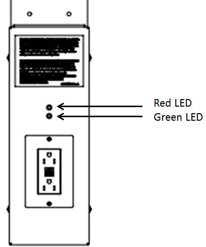
Contents
Model .......................................................................... 1

Safety Precautions ....................................................... 2

Unpacking ................................................................... 4

Packing List ................................................................. 4

General Recommendations.......................................... 5
  Temperature Monitoring ........................................... 5
  Intended Use............................................................ 5
  Initial Loading ........................................................... 5

Operating Standards.................................................... 6
  Unit Specifications.................................................... 6

Installation.................................................................... 8
   Location ................................................................... 8
   Leveling the Unit....................................................... 8
   Castor Installing and Pallet Removal Instructions ...... 8
   Chromatography Refrigerators ................................. 10
   Wiring....................................................................... 10
   Shelves .................................................................... 13
   Installation Instructions ............................................. 13
   Door Operation ........................................................ 13
   Remote Alarm .......................................................... 13
   Final Checks ............................................................ 14

Startup......................................................................... 15
  Initial Startup ............................................................ 15
  Chromatography Refrigerators ................................. 15
Product Loading and Unloading Guidelines .............. 15

Operation..................................................................... 16
  Control Panel ........................................................... 16
  Temperature Setpoint .............................................. 17
  Alarms...................................................................... 17
  Controller Parameter Settings................................... 18

Maintenance ................................................................ 21
 Cleaning the Cabinet Interior .................................... 21
 Cleaning the Unit (Chromatography Refrigerators) .... 21
 Cleaning the Condenser........................................... 21
 Automatic Defrost .................................................... 21
 Gasket Maintenance ................................................ 21
 Alarm Battery Maintenance ...................................... 21
 Preparation for Storage ............................................ 22
 Cleaning the Unit (Chromatography Refrigerators) .... 22
 Replacing Sensor (Chromatography Refrigerators) ... 22
 Sensor Maintenance
 (Chromatography Refrigerators) ............................... 22

Troubleshooting ........................................................... 23

End of Life Care ........................................................... 24

Warranty ...................................................................... 25

Regulatory Compliance ................................................ 26
  Product Safety ......................................................... 26
  Electromagnetic Compatibility .................................. 26
  Energy Efficiency ...................................................... 27
  Additional Regulations and Markings........................ 27
Model
The table below shows the units covered in this operation and
installation manual by model number.
Figure 1. Applicable Models

 Refrigerators

 TSG12RPGA                      TSG45RSLA

 TSG25RPGA                      TSG45CSLA

 TSG25RPSA                      TSG49RPGA

 TSG25RSGA                      TSG49CPGA

 TSG25RSSA                      TSG49RPSA

 TSG30RPGA                      TSG49RSGA

 TSG30CPGA                      TSG49CSGA

 TSG30RPSA                      TSG49RSSA

 TSG30RSGA                      TSG72RPGA

 TSG30CSGA                      TSG72CPGA

 TSG30RSSA                      TSG72RSGA

 TSG45RPLA                      TSG72CSGA

 TSG45CPLA

The annotation of model numbers is given in the following
table:

Table 1. Model Specification

 Series             TSG (Thermo Scientific)

 Size (cu.ft)       12, 25, 30, 45, 49, 72

 Type               R = Refrigerator
                    C = Chromatography

 Exterior           P = Painted
                    S = Stainless

 Door Type          S = Solid
                    G = glass
                    L = Sliding glass

 Voltage            A = 115 V / 60 Hz

General Purpose and Chromatography Refrigerators                Model |   1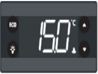
Safety Precautions
In this manual, the following symbols and conventions are       Below are important safety precautions that apply to this
used     .                                                      product.

           WARNING: This symbol when used alone                            CAUTION: Use this product only in the way
           indicates important operating instructions which                described in the product literature and in this
           reduce the risk of injury or poor performance of                manual. Before using it, verify that this product is
           the unit.                                                       suitable for its intended use. If the equipment is
                                                                           used in a manner not specified by the
           WARNING: This symbol indicates potentially
                                                                           manufacturer, the protection provided by the
           hazardous situations which, if not avoided, could
                                                                           equipment may be impaired.
           result in serious injury or death.
                                                                           CAUTION: Do not modify system components,
           WARNING: This symbol indicates situations
                                                                           especially the controller. Use OEM exact
           where dangerous voltages exist and potential for
                                                                           replacement equipment or parts. Before use,
           electrical shock is present.
                                                                           confirm that the product has not been altered in
           WARNING: This symbol indicates potentially                      any way.
           hazardous situations, which if not avoided could
                                                                           WARNING: Your unit must be properly grounded
           result in fire.
                                                                           in conformity with national and local electrical
           CAUTION: This symbol, in the context of a                       codes. Do not connect the unit to overloaded
           CAUTION, indicates a potentially hazardous                      power sources.
           situation which if not avoided could result in
                                                                           WARNING: Disconnect the unit from all power
           minor to moderate injury or damage to the
                                                                           sources before cleaning, troubleshooting, or
           equipment. This indicates a situation which may
                                                                           performing other maintenance on the product or
           result in property damage.
                                                                           its controls.
           CAUTION: This symbol indicates surfaces which
           may become hot during use and may cause a                       WARNING: This unit is not for storage of
           burn if touched with unprotected body parts.                    flammable materials.

           WARNING: Before installing, using or                            WARNING: Units are charged with hydrocarbon
           maintaining this product, please be sure to read                refrigerant (R290). Only qualified service
           the manual and product warning labels carefully.                personnel should service this unit.
           Failure to follow these instructions may cause the
                                                                           WARNING: Unauthorized repair of your unit will
           product to malfunction, which could result in
                                                                           invalidate your warranty. Contact Technical
           injury or damage.
                                                                           Service at 1-866-984-3766 for additional
           CAUTION: This symbol indicates possible pinch                   information.
           points which may cause personal injury.                         DANGER: Risk of fire or explosion. Flammable
                                                                           refrigerant used to be repaired only by trained
           WARNING: The snowflake symbol indicates low
                                                                           service personnel. Do not puncture refrigerant
           temperatures and risk of frost bite. Do not touch
                                                                           tubing.
           bare metal or samples with unprotected body
           parts.                                                          WARNING: No equipment that uses an open
                                                                           flame should be placed inside the refrigerator.
                                                                           This will harm the unit, hamper functionality and
                                                                           compromise your safety.
                                                                           CAUTION: Do not use any battery powered or
                                                                           externally-powered equipment in the refrigerator.

2 |   Safety Precautions                                                 General Purpose and Chromatography Refrigerators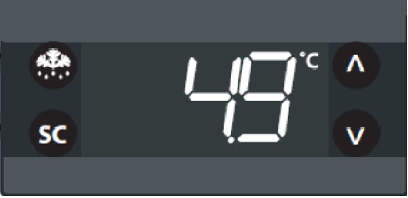
Below are additional safety precautions that apply to
chromatography refrigerator models:

           CAUTION: Equipment should only be powered
           using the internal outlet. In case of a leak the
           safety circuit will remove power to the outlet in
           the unit, but shall have no control over equipment
           power via battery or externally. Do not use
           instrumentation or equipment that incorporates
           potential ignition sources, e.g. open contact
           switching, brushed DC and AC motors, etc.
           CAUTION: The chromatography safety circuit
           has slots/holes at the bottom of the plug panel
           for enabling air to the safety sensor. Do not block
           the Safety Circuit ventilation holes as this will
           diminish and defeat the Safety Circuit.
           WARNING: Do not store or use uncapped
           reagents, vessels and bottles inside the
           chromatography equipment. This may diminish
           functionality of the safety circuit.

General Purpose and Chromatography Refrigerators                 Safety Precautions |   3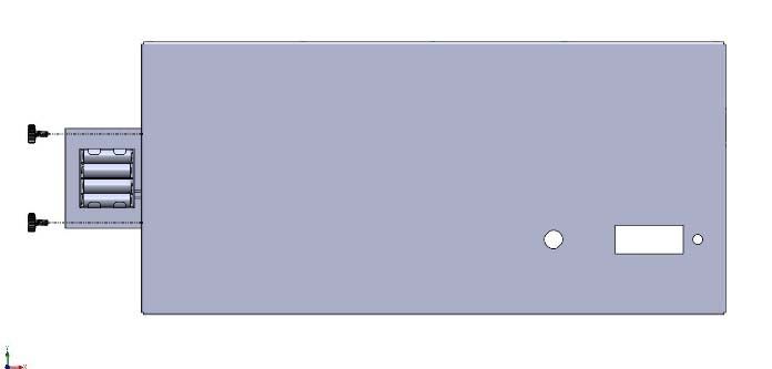
Unpacking
At delivery, examine the exterior for physical damage while
the carrier’s representative is present. If exterior damage is
present, carefully unpack and inspect the unit and all
accessories for damage.
If there is no exterior damage, unpack and inspect the
equipment within five days of delivery. If you find any damage,
keep the packing materials and immediately report the
damage to the carrier.
Do not return goods to the manufacturer without
written authorization.
When submitting a claim for shipping damage, request that
the carrier inspect the shipping container and equipment.

Packing List
Along with the unit, following things will be packed:
•     Installation and Operation manual is placed in the white
      envelope
•     Door Lock Key and Power Key Switch is wire tied to the
      pilaster on the upper top front.
•     Small bag with shelving clips
•     Shelves
•     Half shelves (with chromatography refrigerators)
•     Power cord (with chromatography refrigerators and 25,
      30cf refrigerators)
•     Casters (Applicable for 12, 25, 30cf models only)
•     Wrench (Applicable for 12, 25, 30cf models only)

4 |     Unpacking                                                 General Purpose and Chromatography Refrigerators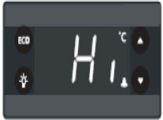
General Recommendations
This section includes some general recommendations for
your unit.

Temperature Monitoring
            IMPORTANT NOTE: We recommend the use of
            a redundant and independent temperature
            monitoring system so that the unit can be
            monitored continuously for performance
            commensurate with the value of product stored.

Intended Use
The refrigerators described in this manual are lab-grade,
general purpose units intended to store non-critical samples
at operating temperatures between 2°C to10°C.
These units are not registered as medical devices or by a
medical device regulatory body (e.g. FDA): that is, they have
not been evaluated for the storage of samples for diagnostic
use or for samples to be re-introduced to the body.
This unit is not intended for use in classified hazardous
locations, nor to be used for the storage of flammable or
corrosive inventory.
This refrigerators are not suitable for outdoor location.

            CAUTION: Storage of unsealed corrosive
            substances may cause the interior of the unit to
            corrode.

Initial Loading
Allow the unit to operate at the desired temperature for a
minimum of 12 hours before loading.
Load the unit one shelf at a time, starting from bottom to top
shelf. After loading each shelf, allow the unit to recover to the
desired set point before loading the next shelf. Repeat this
process until the unit is fully loaded. Please refer to the section
Shelves for shelf load ratings.

            CAUTION: Failure to follow these procedures or
            overloading the unit may cause undue stress on
            the compressors or jeopardize user product
            safety.

General Purpose and Chromatography Refrigerators                      General Recommendations |   5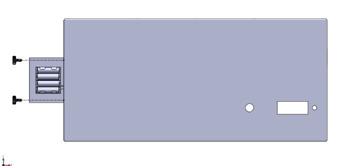
Operating Standards
The units described in this manual are classified for use as
stationary equipment in a Pollution Degree 2 and Over voltage         Unit Specifications
Category II environment.
                                                                      The data label is located on the left side on top towards front
These units are designed to operate under the following
                                                                      of the unit.
environmental conditions:
                                                                      The specifications of refrigerator like voltage, required wall
•     Indoor use
                                                                      breaker amperage and power plug are same for all the units.
•     Altitude up to 2000 m (6512 feet)
                                                                      Voltage = 115 V/60 Hz
•     Maximum relative humidity 60% for temperatures from
                                                                      Breaker Amps = 15 A
      15°C to 32°C (59°F to 90°F)
                                                                      Chromatography Power Plug = NEMA 5-15P
•     Main supply voltage fluctuations not to drop or exceed by
      10% of the nominal voltage                                      General Purpose Refrigerator Power Plug = NEMA 5-15P
•     Do not connect the unit to a GFCI (Ground Fault Circuit         This plug must be plugged into/supplied with it's own
      Interrupter) protected outlet as it may be subject to           individual branch circuit.
      nuisance tripping
                                                                                 CAUTION: Chromatography units are supplied
•     Do not run this unit off the extension cords                               with two separate power cords. Be careful to
                                                                                 unplug both during movement, testing or repair
                                                                                 of the product.

                                                                      Other specifications are listed in the table below.

Table 2. Unit Specifications

    Unit                Size        Exterior         Door         No.of            Exterior Dimensions
                        (Cu.ft.)                     Type         Shelves          (H x W x D)

                                                                                   1925.9 x 628.6 x 635.0 mm
    TSG12RPGA           12          Painted          Glass        4
                                                                                   (75.82 x 24.75 x 25.00 in)

                                                                                   2057.1 x 704.8 x 812.8 mm
    TSG25RPGA           25          Painted          Glass        4
                                                                                   (81.00 x 27.75 x 32.00 in)

                                                                                   2057.1 x 704.8 x 812.8 mm
    TSG25RPSA           25          Painted          Solid        4
                                                                                   (81.00 x 27.75 x 32.00 in)

                                    Stainless                                      2057.1 x 704.8 x 812.8 mm
    TSG25RSGA           25                           Glass        4
                                    Steel                                          (81.00 x 27.75 x 32.00 in)

                                    Stainless                                      2057.1 x 704.8 x 812.8 mm
    TSG25RSSA           25                           Solid        4
                                    Steel                                          (81.00 x 27.75 x 32.00 in)

                                                                                   2057.1 x 781.0 x 812.8 mm
    TSG30RPGA           30          Painted          Glass        4
                                                                                   (81.00 x 30.75 x 32.00 in)

                                                                  4 + 3 Half       2057.1 x 781.0 x 812.8 mm
    TSG30CPGA           30          Painted          Glass
                                                                  Shelves          (81.00 x 30.75 x 32.00 in)

                                                                                   2057.1 x 781.0 x 812.8 mm
    TSG30RPSA           30          Painted          Solid        4
                                                                                   (81.00 x 30.75 x 32.00 in)

6 |     Operating Standards                                                    General Purpose and Chromatography Refrigerators
Table 2. Unit Specifications
Unit Size Exterior Door No.of Exterior Dimensions
(Cu.ft.) Type Shelves (H x W x D)
Stainless 2057.1 x 781.0 x 812.8 mm
TSG30RSGA 30 Glass 4
Steel (81.00 x 30.75 x 32.00 in)
Stainless 4 + 3 Half 2057.1 x 781.0 x 812.8 mm
TSG30CSGA 30 Glass
Steel Shelves (81.00 x 30.75 x 32.00 in)
Stainless 2057.1 x 781.0 x 812.8 mm
TSG30RSSA 30 Solid 4
Steel (81.00 x 30.75 x 32.00 in)
Sliding 2057.1 x 1338.6 x 812.8 mm
TSG45RPLA 45 Painted 8
Glass (81.0 x 52.7 x 32.0 in)
Sliding 8 + 2 Half 2057.1 x 1338.6 x 812.8 mm
TSG45CPLA 45 Painted
Glass Shelves (81.0 x 52.7 x 32.0 in)
Stainless Sliding 2057.1 x 1338.6 x 812.8 mm
TSG45RSLA 45 8
Steel Glass (81.0 x 52.7 x 32.0 in)
Stainless Sliding 8 + 2 Half 2057.1 x 1338.6 x 812.8 mm
TSG45CSLA 45
Steel Glass Shelves (81.0 x 52.7 x 32.0 in)
2057.1 x 1338.6 x 812.8 mm
TSG49RPGA 49 Painted Glass 8
(81.0 x 52.7 x 32.0 in)
8 + 2 Half 2057.1 x 1338.6 x 812.8 mm
TSG49CPGA 49 Painted Glass
Shelves (81.0 x 52.7 x 32.0 in)
2057.1 x 1338.6 x 812.8 mm
TSG49RPSA 49 Painted Solid 8
(81.0 x 52.7 x 32.0 in)
Stainless 2057.1 x 1338.6 x 812.8 mm
TSG49RSGA 49 Glass 8
Steel (81.0 x 52.7 x 32.0 in)
Stainless 8 + 2 Half 2057.1 x 1338.6 x 812.8 mm
TSG49CSGA 49 Glass
Steel Shelves (81.0 x 52.7 x 32.0 in)
Stainless 2057.1 x 1338.6 x 812.8 mm
TSG49RSSA 49 Solid 8
Steel (81.0 x 52.7 x 32.0 in)
2057.1 x 1924.0 x 812.8 mm
TSG72RPGA 72 Painted Glass 12
(81.00 x 75.75 x 32.00 in)
12+ 2 Half 2057.1 x 1924.0 x 812.8 mm
TSG72CPGA 72 Painted Glass
Shelves (81.00 x 75.75 x 32.00 in)
Stainless 2057.1 x 1924.0 x 812.8 mm
TSG72RSGA 72 Glass 12
Steel (81.00 x 75.75 x 32.00 in)
Stainless 12+ 2 Half 2057.1 x 1924.0 x 812.8 mm
TSG72CSGA 72 Glass
Steel Shelves (81.00 x 75.75 x 32.00 in)
General Purpose and Chromatography Refrigerators Operating Standards | 7Installation
WARNING: Do not exceed the electrical rating Without Forklift
printed on the data plate located on the upper left
side of the unit. Required Tools: Phillips head screwdriver, 7/16” and 3/8”
wrenches, and a minimum of 2 people.
All the units are shipped with factory installed feet with rolling
Location casters supplied inside of the unit. The following instructions
demonstrate how to remove the cabinet from its shipping
base (pallet) and install the casters without use of a forklift.
Install the unit on a level area free from vibration with minimum
3 inches of clearance on all sides and 4 inches on top. Do not
position the equipment in direct sunlight or near heating
diffusers, radiators, or other sources of heat.
Note: Do not move the unit in fully loaded condition.
Leveling the Unit
The refrigerator must be level in order to provide adequate
condensation drainage as well as proper door alignment and
operation. The refrigerator should be in its final operating
location and set so that it is firmly positioned on the floor.
Level the cabinet front to rear and side-to-side using the
corner leveling screws. The front leveling screws are
accessed by removing the base grill, as described below:
1. Remove the lower grill attachment screws Note: The unit should be unpacked near the desired final
location.
2. Grasp the grill with both hands
1. Remove the packaging and kick plates from unit.
3. Lift the grill approximately 1/2" Remove additional packaging to access the interior of the
4. Pull grill away from the refrigerator cabinet. Be sure to keep one cardboard corner for
subsequent step.
2. Using a screwdriver, remove the screws holding on the
Castor Installing and Pallet front grill. Lift grill upwards and pull away from unit to
remove. Set aside.
Removal Instructions 3. Remove bolts (4) holding the unit to the pallet using the
7/16” wrench.
CAUTION: Avoid damage to the refrigerant
tubing which may cause a refrigerant leak while
handling, moving, and operating this unit.
Note: Casters available for 12, 25, and 30 cu. ft. units;
leveling feet only on 45, 49, and 72 cu. ft. units
Note: From this step onward, a minimum of 2 people are
required. Use additional people if necessary.
4. With one person on each side, gently slide the unit
towards the side edge of the pallet. Slide the unit so that
8 | Installation General Purpose and Chromatography Refrigeratorsthere are approximately 3 inches of overhang to allow the 7. Gently rotate unit to install the last caster.
removal of the factory installed feet and installation of the Person 2: Continue supporting the unit at the floor end.
casters. Person 1: Install 1 caster on the front of unit. Tighten
using caster wrench supplied.
CAUTION: Two people are always required to 8. Take a cardboard packaging corner, fold in half, and
move the unit. Never move or adjust unit when place under the pallet/unit with the fold away from the
some one is working on the unit (i.e. adjusting pallet. Gently position unit parallel with the pallet using the
casters). edge of the unit to support the pallet. Once in position,
gently roll the unit off of the pallet.
5. Person 1: Remain standing on the side of the pallet and
providing additional unit support. Person 2: Remove all 4
factory installed feet (using the 3/8” wrench to loosen if
necessary). Install 2 casters on the overhang edge.
Tighten using caster wrench supplied.
Note: Some casters lock and others do not. It is
recommended to install the locking casters on the front of the
unit.
6. While supporting the unit, carefully slide the unit until the
casters reach the ground. Gently slide the back edge off
of the pallet approximately 3 inches to allow for
installation of the back caster. Person 2: Continue
supporting the unit at the floor end. Person 1: Install 1
caster on the back of the unit. Tighten using caster
wrench supplied.
With Forklift
Required Tools: Phillips Head Screwdriver, 7/16” and 3/8”
Wrenches, and a minimum of 2 people.
The following instructions demonstrate how to remove the
cabinet from its shipping base (pallet) and install the casters or
lower legs using a fork truck.
1. Remove the screws, bolts and caster by following the
instructions given in section Without Forklift.
Note: Always use caution when lifting unit with forklift to
ensure not to damage or drop unit.
General Purpose and Chromatography Refrigerators Installation | 92. Carefully position forks to lift unit from rear. Ensure unit is The outlet assembly has two LEDs:
fully positioned on fork truck prior to raising the forks.
• RED (on the top) - When the red LED is ON, it indicates
there is no power to the AC outlet inside the unit.
• GREEN (on the bottom) - When the green LED is ON, it
indicates there is power to the AC outlet inside the unit.
3. Raise the unit approximately six inches to allow access to
the feet and casters. Person 1: Stand at the front of the
unit and provide additional support to the unit. Person 2:
If feet are desired, lower all 4 factory installed feet (using
the 3/8” wrench to loosen if necessary). If rolling casters
are desired, remove the feet and install the 4 casters and
tighten using caster wrench supplied.
Note: Some casters lock and others do not. It is advised to
install the locking casters on the front of the unit.
4. Remove pallet from below the unit and gently lower unit
in desired location.
Chromatography Switches
Refrigerators The Chromatography refrigerators has a reset switch on the
right side of the header panel, above remote alarm contacts.
The chromatography refrigerator is equipped with a safety • Chromatography Manual Reset: This is used to manually
circuit. In the event the safety circuit is tripped (the safety reset the safety circuit in the AC receptacle assembly
sensor senses a flammable gas), the power to the internal after the LED turns RED from GREEN due to a safety trip
outlet will be discontinued and the user will need to manually event which disengages power to outlet inside the
reset the safety circuit assembly using the reset switch at the refrigerator. It is present on the right side top front corner
right side of header panel before power is restored. To do next to the remote alarm contacts.
this, toggle the switch located on the top right side of the
header panel beside the remote alarm contacts. There will be
a power delay to the outlet for approximately 4 minutes where
the red LED will be illuminated.
Wiring
When power is available at the outlet, the red LED will turn off The wiring diagram for the units is shown in Figure 2.
and the green LED will illuminate.
CAUTION: Connect the equipment to the
If the circuit trips from RED back to GREEN repeatedly or
correct power source. Incorrect voltage can
never turns GREEN, please contact Customer Service.
result in severe damage to the equipment.
Flammable materials should not be stored in the refrigerator.
CAUTION: For personal safety and trouble-free
operation, this unit must be properly grounded
Lights while in use. Failure to ground the equipment
may cause personal injury or damage to the
equipment. Always conform to the National
The GFCI outlet assembly is located inside the unit back in the Electrical Code and local codes. Do not connect
center. the unit to overloaded power lines.
10 | Installation General Purpose and Chromatography RefrigeratorsCAUTION: Always connect the unit to a
dedicated (separate) circuit. Each unit is
equipped with a service cord and plug designed
to connect it to a power outlet which delivers the
correct voltage. Supply voltage must be within
±10% of the unit rated voltage. If cord becomes
damaged, replace with a properly rated power
supply cord. Power Cord Specifications: 3-G 12
AWG, NEMA 5-15 P, 15A / 125V.
CAUTION: Never cut the grounding prong from
the service cord plug. If the prong is removed, the
warranty is invalidated.
CAUTION: Disconnect the power cord in case of
emergency.
General Purpose and Chromatography Refrigerators Installation | 1112 |
%52:1
%/8(:+,7( %/8( :+,7(
1'(9$3)$121
/$5*(581,7621/<
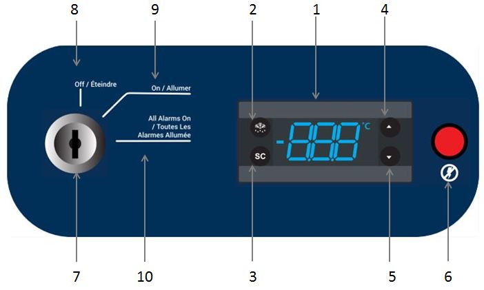
$&287/(7 (0,),/7(521/2. Insert top of the clip into the desired hole of the pilaster
Shelves the retaining tab should be facing upwards.
3. Rotate the clip downwards and insert the bottom tab into
All the units come standard with wire shelves. Each unit has
the appropriate hole, the clip may be squeezes slightly
different number of shelves. Refer to Table 2 for more
during installation.
information.
4. Install shelves onto clips with the product retention bar
Maximum shelf capacity is 45 kg (100 lbs) for full shelves and
facing upwards, be careful not to is lodge clips during
22.5 kg (50 lbs) for half shelves.
shelve installation.
For safety in shipping, the shelves are packaged and secured
5. Prior to loading the shelf, ensure that the shelf is resting
inside the cabinet. Insert the shelf support hangers (included
on each of 4 clips and the clips are installed.
with the manual inside the unit) into the built-in shelf supports
(located on the inside walls of the cabinet interior) at the
desired locations. CAUTION: Improper shelf clip installation may
cause shelf and/or product damage to the unit.
CAUTION: Do not overload the shelves, the unit
is designed to utilize all shelves that are supplied
in an equally spaced manner.
Door Operation
The swinging door units are designed to stay open if opened
90 degrees or more. The door spring tension cannot be
adjusted.
The Sliding doors can be opened completely towards left or
right. If the self-closing door does not work properly, make
Figure 3. Shelf Arrangement sure the unit is leveled properly
Door Seal
CAUTION: Door seal integrity is critical for unit
performance. A loose fitting gasket allows moist
air to be drawn into the cabinet, resulting in
quicker frost buildup on the cabinet walls, longer
running time, poor temperature maintenance and
increased operation cost.
Remote Alarm
Figure 4. Shelf Clip
All units have factory-installed remote alarm contacts that can
be used for remote alarm systems. The maximum distance
between a unit and a remote alarm depends on the wire
Installation Instructions gauge used. Refer to Table 4 below:
The Remote alarm contacts are located on the right side of
WARNING: Do not to move this unit while the header panel. The three terminals are: COMMON, OPEN
loaded ON FAIL (Normally Closed) and CLOSE ON FAIL (Normally
Open).
1. Determine proper location for shelves clips, the reference
number on the pilaster can serve as a guide to ensure all
clips are properly located.
General Purpose and Chromatography Refrigerators Installation | 13Table 3. Wire Gauge and Distance to Remote Alarm Wire Total Wire Distance to Alarm 1/2 Gauge Length (feet) Wire Length (feet) 20 530 265 18 840 420 16 1330 665 14 2120 1060 12 3370 1685 To install the remote alarm, make the following connections: 1. Connect the COMMON terminal on the cabinet switch to the COMMON wire on the alarm. 2. To get an alarm when the switch contacts open, connect the OPEN ON FAIL terminal on the cabinet to the OPEN ON FAIL wire on the alarm. 3. To get an alarm when the switch contacts close, connect the CLOSE ON FAIL terminal on the cabinet to the CLOSE ON FAIL wire on the alarm. The COMMON and CLOSE ON FAIL wires must be tied together in this application 4. Plug the alarm system service cord into an electrical outlet. 5. The contacts will trip in the event of high temperature alarm or low temperature alarm. Final Checks Before start up, be sure to complete the following steps: 1. Make sure that the unit is free of all wood or cardboard shipping materials, both inside and outside. 2. Check the positions of the shelves. If you want to adjust the positions. 3. Verify that the unit is connected to a dedicated circuit. 14 | Installation General Purpose and Chromatography Refrigerators
Startup
                                                                     Operating equipment inside the refrigerator may shift the
Initial Startup                                                      temperature profile in the unit. Monitor the refrigerator as
                                                                     needed for any such shift.
To start up the unit, complete the following steps:
1. Connect the AC main power cord. The evaporator fans
   start when the power cord is plugged in.                          Product Loading and
2. Insert the silver colored key in the switch and turn to the
   Power On position.                                                Unloading Guidelines
3. Allow the unit to reach operating temperature before
   loading it with any product. To stabilize the temperature         When loading your unit, take care to observe the following
   profile, a 24-hour waiting period is recommended.                 guidelines:

4. If you desire to enable the power failure alarm, turn the         •   Distribute the load as evenly as possible. Temperature
   three position key switch one turn further clockwise to               uniformity depends on air circulation, which could be
   the All Alarm On position.                                            impeded if the internal storage components are overfilled,
                                                                         particularly at the top of the cabinet.
5. If you have a remote alarm, hook it up at this point (refer
   to section Remote Alarm).                                         •   For critical applications, be sure that the alarm systems
                                                                         are working and active before you load any product.
6. If desired, lock the cabinet door using the silver colored
   key. Place duplicate key copies in a safe place.                  •   Ensure clearance between the top of the cargo and the
                                                                         bottom of the internal storage components. Lack of
All controls should now be fully operational, the alarm active (if       clearance may affect unit performance or impede
enabled), and all visual indicators active.                              operation of the storage component.

Chromatography
Refrigerators
1. Connect the AC main power cord.
2. Connect the GFCI AC power cord.
3. Make sure the reset switch is in ON position.
4. Insert the silver colored key in the switch and turn to the
   Power On position. The display will show the actual
   cabinet temperature.
Note: The Chromatography refrigerator is shipped with the
manual reset switch at the top right side front of the header
panel above the remote alarm contacts (refer to section
Switches) as ON. The Manual reset switch should always be
in ON position.
5. The red LED on the chromatography safety circuit turns
   ON.
6. After a power delay of 4 minutes the red LED on the
   chromatography safety circuit turns Off and the green
   LED on the chromatography safety circuit turns ON.
Note: During initial power-up, the GFCI outlet will not be
powered until after an approximate 4 minute delay.

General Purpose and Chromatography Refrigerators                                                                      Startup |     15
Operation
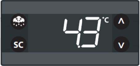
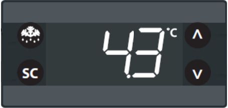
Control Panel
Figure 5. Control Panel
1. Display: During normal operation, the display shows 3. SC: This button is used to turn the cabinet LED light on
cabinet temperature in degree Celsius as measured by and off with a single touch. This button is also used for
the primary sensor. When Alarm and Compressor are selecting an option in parameters.
active, the respective LED’s will be displayed. Refer to the
4. Up: Scrolls the menu items and increases the values.
table below for LED display symbols. A display code will
also be visible during the functioning based on the type of 5. Down: Scrolls the menu items and decrease the values.
alarm. 6. Power Fail LED: This LED indicates the power failure
situation in the unit.The flash light indicate power failure
Defrost LED Alarm LED Compressor LED situation.
7. Key Switch: Used to turn the power to the controller and
power failure alarm on and off.
Note: This is not a primary disconnect device, thus even
if the key switch is Off the fan will be On as it is hard wired.
Please remove the power cord to completely turn Off the
On Fixed: On Fixed: On Fixed:
unit.
Defrost Active Alarm Present Compressor Active
Off: Defrost Flashing: Alarm Flashing: Delay, 8. Off: Turns the power to the controller off.
Off Silenced Protection or 9. Power On: Turns On power to the controller and used as
Off: No Alarm
Activation Blocked to silence the power failure alarm.
Off: No Alarm 10. All Alarm ON: Turns On the audible power fail alarm.
2. Defrost: This button is used to manually defrost the unit
as well as to go back from the parameter settings.
16 | Operation General Purpose and Chromatography RefrigeratorsAfter 30 seconds, the display automatically reverts to the
Temperature Setpoint current temperature.
The factory default temperature setpoint is 5°C for all
laboratory refrigerators. Adjusting the setpoint is not
recommended. In case the setpoint has to be changed, follow
the instructions given below.
The display shows the current temperature.
Alarms
The alarm system is designed to provide visual and audible
warning signals for both power failure and rise in temperature.
The alarm is equipped with a battery backup.
Press Up / Down button to increase / decrease setpoint
temperature. The power failure alarm system is activated only when the key
switch is turned to the Power Failure Alarm ON position.
Low temperature, high temperature and door ajar alarms are
set to ON position by default as soon as the controller is
turned on. These cannot be turned off.
Default low and high alarm values are 2°C and 10°C. These
values may be adjusted, following instructions in section
Temperature Setpoint.
Note: There is no door open alarm on sliding door model.
The audible warning signal sounds when there is a power
failure, temperature alarm condition, or when the door is ajar
for more than 1 minute.
Alarm display codes for high temperature, low temperature,
sensor failure, door ajar are mentioned in Table 5.
Table 4. Alarm Codes
Alarm Trigger Automatic Outputs Comments
code clearance
“Hi” Air temperature is User Configured Blink “Hi” with the highest
higher than “ALA- temperature; If configured: cut in
High temperature alarm
>Hat” for “ALA- alarm relay, beep the buzzer
>Htd”
“Lo” Air temperature is User Configured Blink “Lo” with the lowest
less than “LAt” for temperature; If configured: cut in Low temperature alarm
“Ltd” alarm relay, beep the buzzer
“dor” Door open for more Always Blink “dor”. If configured: cut in
Door open alarm
than “ALA->dod” alarm relay, beep the buzzer
“E01” “S1” error Always Blink “E01”. If configured: cut in “S1” sensor failure = (short
alarm relay, beep the buzzer or open)
“E02” “S2” error Always Blink “E02”. If configured: cut in “S2” sensor failure = (short
alarm relay, beep the buzzer or open)
General Purpose and Chromatography Refrigerators Operation | 17Alarm Silencing Password Protection
To mute the power fail alarm, change the key-switch to Power The unit is password protected except the setpoint which can
ON position. The power fail alarm will not be audible but the be adjusted without the password. The default password is 0.
Red LED will be displayed on the control panel.
To change the parameters, password is required to be
The high temperature, low temperature, sensor failure and entered.
door ajar alarms can be silenced by pressing any key on the
1. Hold “Up / Down” button for 5 seconds.
controller.
2. The display will show “PAS” after which brief delay
When the alarm is active, the alarm code flashes alternately
changes to 000.
with the temperature and the alarm symbol.
3. Press SC to confirm.
You have now entered the controller parameters menu.
To change the password, you need to go to parameter
settings.
1. Enter the current password as given above and get to the
Once the alarm is silenced, the code stops flashing but the menu.
temperature and the alarm symbol is still displayed. 2. Scroll down to “ASi” group.
3. Press “SC” button to confirm.
4. Scroll to “PS1” parameter and Press “SC” button to
confirm.
5. Scroll “Up / Down” buttons to enter the desired
password.
6. Press “SC” button to confirm.
After 30 seconds, the display automatically reverts to showing
Controller Parameter the current temperature. If this does not happen, press the
Defrost button twice.
Settings
To access the controller settings you need to enter the
password and the access level will determine which
parameter you can view and edit.
Table 5. Parameter List
Category Abv Description All Single All Sliding All Double
Doors Doors and Triple
Door Models
tHE Thermostat settings
SEt Set Point 5°C 5°C 5°C
SPr Set Point Adjustment Ratio 0.2°C 0°C 0°C
diF Differential 1.1°C 1.1°C 1.1°C
HSE High Set Point 6°C 6°C 6°C
LSE Low Set point 2°C 2°C 2°C
dEF Defrost Settings
dFt Def. Type nAt nAt nAt
18 | Operation General Purpose and Chromatography RefrigeratorsTable 5. Parameter List
Category Abv Description All Single All Sliding All Double
Doors Doors and Triple
Door Models
Add Adaptive Defrost Yes Yes Yes
dtt Def Terminate Temp 4°C 4°C 4°C
drt Def Reset Temp 2°C 2°C 2°C
dii Def Min Interval 1 hour 1 hour 1 hour
dAi Def Max Interval 1 hour 1 hour 1 hour
dit Def Min Time 5 min 5 min 5 min
dAt Def Max Time 30 min 30 min 30 min
dot Drip Off Time 0 min 0 min 0 min
fdd Fan Delay After Defrost 0 sec 0 sec 0 sec
ftd Fan Start Temp 10°C 10°C 10°C
dFa Defrost Fan On Yes Yes Yes
dCt Defrost On Compressor Time No No No
doC Defrost by Comp. Running Time 1 hour 1 hour 1 hour
dEt Defrost Start Evaporator Temp 0°C 0°C 0°C
ddt Defrost Delta T 3.0 k 3.0 k 3.0 k
idi Initial Defrost Interval 0 hour 0 hour 0 hour
idd Initial Defrost Duration 0 cycle 0 cycle 0 cycle
CoP Compressor Settings
uPt Voltage Protection No No No
uLi Minimum Cut-in Voltage 0 VAC 0 VAC 0 VAC
uLo Minimum Cut-out Voltage 0 VAC 0 VAC 0 VAC
uHi Maximum Voltage 270 VAC 270 VAC 270 VAC
EHd Sensor Error Type SEt SEt SEt
Ert Error Run Time 10 min 10 min 10 min
ESt Error Stop Time 7 min 7 min 7 min
CSt Min Stop Time 2 min 2 min 2 min
crt Min Run Time 2 min 2 min 2 min
Cot Max Off Time 0 min 0 min 0 min
Cdd Compressor Door Open Delay 0 min 0 min 0 min
Srt System Resume After Door Open 0 min 0 min 0 min
Pod Power On Delay 60 sec 60 sec 60 sec
General Purpose and Chromatography Refrigerators Operation | 19Table 5. Parameter List
Category Abv Description All Single All Sliding All Double
Doors Doors and Triple
Door Models
Pot Power ON Temperature 16°C 16°C 16°C
diS Display Settings
diC Display Intensity Auto Control No No No
din Display Intensity 8 8 8
CFu Display Unit C C C
trS Temp Sensor to Display Sco Sco Sco
rES Display Resolution 1 1 1
rLT Display Range Limit No No No
ddL Display Delay 1 min 1 min 1 min
doF Display Offset 0.0 K 0.0 K 0.0 K
dLt Lock-Time After Defrost 15 min 15 min 15 min
SEC Show Economy/Night Mode No No No
SHo Show Holiday No No No
Sdf Show Defrost No No No
SCS Show Compressor Symbol Yes Yes Yes
SFS Show Fan Symbol No No No
SdS Show Defrost Symbol No No No
SES Show ECO Symbol No No No
idP Info Menu Display Item 15 15 15
SSC Show Pull Down No No No
ALA Alarm Settings
HAt High Temp Alarm 10°C 10°C 10°C
LAt Low Temp Alarm 2°C 2°C 2°C
Htd High Alarm Delay 0 min 0 min 0 min
Ltd Low Alarm Delay 0 min 0 min 0min
dod Door Open Delay 1 min 1 min* 1 min
ACA Auto Clearance of Alarm Yes Yes No
Note: *45 cu. ft. sliding door models do not have door ajar alarms.
20 | Operation General Purpose and Chromatography RefrigeratorsMaintenance
1. Disconnect the power.
Cleaning the Cabinet 2. Vacuum the condenser and clean up any loose dust.
Interior 3. Reconnect power.
WARNING: Disconnect equipment from main
power before attempting any maintenance to
equipment or its controls unless stated Automatic Defrost
otherwise.
The defrosting process on all the models is primarily
accomplished by air circulated during off-cycle. This heat free
To clean the cabinet interior, remove the shelves, use a
process ensures that the temperature is not affected by the
solution of water and a mild detergent for cleaning. Rinse the
defrost cycle. Defrost cycle works on adaptive defrost
interior storage components and wipe them dry with a soft
method which is both temperature and time controlled.
cloth.
When the evaporator sensor reaches below 0°C, the defrost
cycle will be initiated. Initially the defrost cycle continues for a
minimum duration of 5 minutes and after that the defrost
Cleaning the Unit cycle will be terminated once the evaporator sensor
temperature reaches 4°C. In case the evaporator sensor
(Chromatography doesn’t reach the temperature of 4°C within 30 minutes from
the start of defrost cycle, the defrost cycle will be terminated.
Refrigerators)
Use a solution of water and a mild detergent for cleaning.
Lightly spray the interior storage components and wipe them
Gasket Maintenance
dry with a soft cloth or spray the cloth first and then wipe
interior surfaces. Periodically check the gaskets around the door for punctures
or tears. Leaks are indicated by condensation or frost which
Do not spray or pour directly into holes and gaps in the form at the point of gasket failure. Make sure that the cabinet
chromatography safety circuit assembly for cleaning. Use a is level.
wet wipe to clean around sensor box and outlet.
Keep the door gaskets clean and frost free by wiping gently
If the sensor led turns red after cleaning, manually reset the with a soft cloth.
safety circuit assembly using the manual reset switch at the
back of the unit. To check the door seal, complete the following steps:
1. Open the door
2. Insert a strip of paper (a couple of inches wide) between
Cleaning the Condenser the door gasket and the cabinet flange and close the
door.
CAUTION: Condensers should be cleaned at 3. Slowly pull the paper strip from the outside. You should
least every six months; more often if the feel some resistance.
laboratory area is dusty. In heavy traffic areas,
4. Repeat this test at 4-inch intervals around the door. If the
condensers load with dirt more quickly. Failure to
door does no seal properly, replace the gasket.
keep the condenser clean can result in
equipment warm-up or erratic temperatures.
CAUTION: Never clean around the condensers
with your fingers. Some surfaces are sharp.
Alarm Battery
Maintenance
The condenser is located in the bottom front of the unit.
To clean the condenser, complete the following steps: Unit comes with (4) AA Alkaline 1.5 V batteries. The back-up
time for the alarm battery system is 60 hours. Battery must be
General Purpose and Chromatography Refrigerators Maintenance | 21replaced after an active alarm or after every 12 months,
whichever is the earliest. Cleaning the Unit
Steps to follow for battery replacement: (Chromatography
1. Locate the knurled/thumb screw on the left side of the
header panel. Refrigerators)
Use a solution of water and a mild detergent for cleaning.
Lightly spray the interior storage components and wipe them
dry with a soft cloth or spray the cloth first and then wipe
interior surfaces.
Do not spray or pour directly into holes and gaps in the
chromatography safety circuit assembly for cleaning. Use a
wet wipe to clean around sensor box and outlet.
If the sensor led turns red after cleaning, manually reset the
2. Remove the knurled/thumb screw by hand. safety circuit assembly using the manual reset switch on the
right side of header panel.
Replacing Sensor
(Chromatography
Refrigerators)
3. Once the screws are removed, wear hand gloves and
The sensor needs replacement if the temperature goes below
gently pull the bracket out until you see the batteries
freezing in the cabinet. Use system alarms to ensure the
completely.
temperature inside the unit is always above 0°C. If exposed to
freezing conditions the sensor should be replaced.
If the display shows an error and sounds an alarm (in case of
a control, defrost, bottle or ambient probe failure), the sensor
needs to be replaced.
Sensor Maintenance
4. Replace the batteries and gently close the bracket. Once
the bracket is closed, Align the holes on the bracket and
(Chromatography
header panel, screw using the knurled/thumb screw.
Refrigerators)
The sensor should be replaced every five years by a trained
Preparation for Storage service provider.
If the unit is going to be stored in an off condition, allow the
unit to warm up and dry out with the door open before moving
into storage.
22 | Maintenance General Purpose and Chromatography RefrigeratorsTroubleshooting
WARNING: Troubleshooting procedures involve
working with high voltages which can cause
injury or death. Troubleshooting should only be
performed by Factory Authorized Service
Personnel.
This section is a guide for troubleshooting equipment problems. Component parts must be replaced only with like components.
Table 6. Troubleshooting Procedure
Problem Cause Solution
Check that the cord is securely plugged in. Plug
Power supply
another appliance into the outlet to see if it is live.
Unit does not operate or Test the voltage and verify that it is correct for your
power failure indicator is on unit Check if there is any frost build up on
Unit overloaded
refrigeration coils. Turn unit off and allow it to
defrost. Remove contents from top shelf of unit.
Unit runs continuously Dirty condenser Clean condenser
Control setting too high Reset control
Space temperature too high
Inadequate air circulation Improve air movement
Temperature control Make sure that the control is set correctly.
Condenser clogged Make sure the condenser is clean.
Temperature fluctuates/
insufficient cooling If the temperature control is set correctly, the
Other causes condenser is clean, but temperature continues to
fluctuate, call an authorized service representative.
The equipment makes too Place the equipment on an even surface or use
The equipment is not level
much noise adjustable feet.
Refrigerator freezing Temperature control Reset control
Door is open Make sure the door is completely closed.
Door seal check Check the door seal
Warm product recently loaded in Allow ample time to recover from loading warm
unit product.
Check for proper voltage to the unit. If there is no
Power supply
Unit warms up voltage to the unit, call an electrician.
If the compressor is not running and the power
audible is on, have an electrician check for proper
voltage to the unit.
Compressor not functioning
If the compressor is not running and the power
failure alarm is off, call the customer service for
assistance.
Unit noisy Loose parts or mountings Find and tighten
General Purpose and Chromatography Refrigerators Troubleshooting | 23End of Life Care Be sure to follow local regulations when disposing of an old unit. Some suggestions are listed below: 1. Remove items and defrost unit. Be sure to clean up any biological safety hazards. 2. Remove the cabinet door to help prevent entrapment inside of a unit. 3. Have a certified technician remove the refrigerant and compressor, then drain the compressor and oil from the system. Dispose of components following local regulations. 24 | End of Life Care General Purpose and Chromatography Refrigerators
Warranty
Domestic Warranty • 24 Months Parts and Labor, 5 years for compressor
International Warranty • 24 Months Full Warranty Parts
During the first twenty four (24) months from shipment, Thermo Fisher Scientific Inc, through its authorized Dealer or service
organizations, will at its option and expense repair or replace any part found to be non-conforming in material or workmanship.
Thermo Fisher Scientific Inc reserves the right to use replacement parts, which are used or reconditioned. Replacement or
repaired parts will be warranted for only the unexpired portion of the original warranty.
This warranty does not apply to damage caused by (i) accident, misuse, fire, flood or acts of God; (ii) failure to properly install,
operate or maintain the products in accordance with the printed instructions provided, (iii) causes external to the products such
as, but not limited to, power failure or electrical power surges, (iv) improper storage and handling of the products, (v) use of the
products in combination with equipment or software not supplied by Thermo Fisher; or (vi) installation, maintenance, repair,
service, relocation or alteration of the products by any person other than Thermo Fisher or its authorized representative. To
obtain proper warranty service, you must contact the nearest authorized service center or Dealer. Thermo Fisher Scientific,
Inc’s own shipping records showing date of shipment shall be conclusive in establishing the warranty period. At Thermo
Fisher’s option, all nonconforming parts must be returned to Thermo Fisher postage paid and replacement parts are shipped
FOB Thermo Fisher’s location.
Limitation of Liability:
THIS WARRANTY IS EXCLUSIVE AND IN LIEU OF ALL OTHER WARRANTIES, WHETHER WRITTEN, ORAL, OR IMPLIED. NO
WARRANTIES OF MERCHANTABILITY OR FITNESS FOR A PARTICULAR PURPOSE SHALL APPLY. THERMO FISHER
DOES NOT WARRANT THAT THE PRODUCTS ARE ERROR-FREE OR WILL ACCOMPLISH ANY PARTICULAR RESULT.
THERMO FISHER SHALL NOT BE LIABLE FOR ANY INDIRECT OR CONSEQUENTIAL DAMAGES INCLUDING, WITHOUT
IMITATION, DAMAGES TO LOST PROFITS OR LOSS OF PRODUCTS.

General Purpose and Chromatography Refrigerators                                                                   Warranty |    25
Regulatory Compliance
Product Safety

Product Testing
This product family has been tested to applicable product safety standards by Underwriters Laboratories
(UL), which is a Nationally Recognized Test Laboratory (NRTL).

Hydrocarbon Refrigerants
According to U.S. Code of Federal Regulation 40 Part 82, this refrigerator employs the natural hydrocarbon refrigerant R290.
Because of the nature of hydrocarbon refrigerants, for mechanical repair, such as recharge or compressor replacement, should
only be carried out by a certified refrigeration technician. The safety of this equipment is listed by Underwriter Laboratory (UL)
under Standard UL471, section SB – “natural refrigerant”.

Electromagnetic Compatibility

FCC Statement (USA)
               Any changes or modifications not expressly approved by the party responsible for compliance could void the
               user’s authority to operate the equipment.

Note: This equipment has been tested and found to comply with the limits for a Class A digital device, pursuant to part 15 of
the FCC Rules. These limits are designed to provide reasonable protection against harmful interference when the equipment is
operated in a commercial environment. This equipment generates, uses, and can radiate radio frequency energy and, if not
installed and used in accordance with the instruction manual, may cause harmful interference to radio communications.
Operation of this equipment in a residential area is likely to cause harmful interference in which case the user will be required to
correct the interference at his own expense.

Canadian ISED IC Notice
This ISM device complies with Canadian ICES-001.
Cet appareil ISM est conforme à la norme NMB-001 du Canada.

26 |    Regulatory Compliance                                                General Purpose and Chromatography Refrigerators
Energy Efficiency ENERGY STAR This product family has been voluntarily evaluated, and found compliant, by an EPA approved certification body to the EPA ENERGY STAR Laboratory Grade Refrigerators and Freezers Specification 1.1. Additional Regulations and Markings This product is not marked with a CE marking, as it does not operate in the voltage range to be sold to the EU Member States or European Economic area (EEA). Please reach out to the manufacturer for questions regarding any additional regulatory conformity. General Purpose and Chromatography Refrigerators Regulatory Compliance | 27
WEEE Comphliance
WEEE Compliance. This product is required to comply with the European Union’s Waste Electrical & Great Britain
Electronic Equipment (WEEE) Directive 2012/19/EU. It is marked with the following symbol. Thermo
Fisher Scientific has contracted with one or more recycling/disposal companies in each EU Member
State, and this product should be disposed of or recycled through them.

WEEE Konformittät. Dieses Produkt muss die EU Waste Electrical & Electronic Equipment (WEEE) Deutschland
Richtlinie 2012/19/EU erfüllen. Das Produkt ist durch folgendes Symbol gekennzeichnet. Thermo
Fisher Scientific hat Vereinbarungen getroffen mit Verwertungs-/Entsorgungsanlagen in allen EU-Mit-
gliederstaaten und dieses Produkt muss durch diese Firmen widerverwetet oder entsorgt werden.

Conformità WEEE. Questo prodotto deve rispondere alla direttiva dell’ Unione Europea 2012/19/EU            Italia
in merito ai Rifiuti degli Apparecchi Elettrici ed Elettronici (WEEE). È marcato col seguente simbolo.
Thermo Fischer Scientific ha stipulato contratti con una o diverse società di riciclaggio/smaltimento in
ognuno degli Stati Membri Europei. Questo prodotto verrà smaltito o riciclato tramite queste medes-
ime.

Conformité WEEE. Ce produit doit être conforme à la directive euro-péenne (2012/19/EU) des                 France
Déchets d’Equipements Electriques et Electroniques (DEEE). Il est marqué par le symbole suivant.
Thermo Fisher Scientific s’est associé avec une ou plusieurs compagnies de recyclage dans chaque
état membre de l’union européenne et ce produit devraitêtre collecté ou recyclé par celles-ci.
IF YOU NEED ASSISTANCE:
Thermo Fisher Scientific products are backed by a global technical support team ready to support your applications. We offer
cold storage accessories, including remote alarms, temperature recorders, and validation services.
Visit www.thermofisher.com/cold or call:

 Countries                                      Sales

 North America                                  +1 866 984 3766

 India toll free                                1800 22 8374

 India                                           +91 22 6716 2200

 China                                          +800 810 5118, +400 650 5118

 Japan                                          +81 3 5826 1616

 Australia                                      +61 39757 4300

 Austria                                        +43 1 801 40 0

 Belgium                                        +32 53 73 42 41

 France                                         +33 2 2803 2180

 Germany international                          +49 6184 90 6000

 Germany national toll free                     0800 1 536 376

 Italy                                          +32 02 95059 552

 Netherlands                                    +31 76 579 55 55

 Nordic/Baltic/CIS countries                    +358 9 329 10200

 Russia                                         +7 812 703 4215

 Spain/Portugal                                 +34 93 223 09 18

 Switzerland                                    +41 44 454 12 22

 UK/Ireland                                     +44 870 609 9203

 New Zealand                                    +64 9 980 6700

 Other Asian Countries                          +852 2885 4613

 Countries not listed                           +49 6184 90 6000

Thermo Fisher Scientific Inc.
275 Aiken Road
Asheville, NC 28804
United States

Find out more at thermofisher.com/cold
© 2018 Thermo Fisher Scientific Inc. All rights reserved. All trademarks are the property of
Thermo Fisher Scientific and its subsidiaries unless otherwise specified. 329137H01 0818
Réfrigérateurs de chromatographie
et à usage général
Série TSG
Installation et fonctionnement
329137H01 • Révision B • août 2018
IMPORTANT Lisez ce mode d'emploi. Le non-respect des consignes du présent manuel peut entraîner des
dégâts au niveau de l'unité, des blessures au personnel et de mauvaises performances de l'équipement.

ATTENTION Tous les réglages internes et la maintenance doivent être exécutés par un personnel de service
qualifié.

Le présent manuel est publié à titre d'information uniquement. Le contenu et le produit qu'il décrit peuvent
être modifiés sans préavis. Thermo Fisher Scientific ne fait aucune déclaration ni ne donne aucune garantie
quant à ce manuel. En aucun cas Thermo ne saurait être tenu responsable des dommages, directs ou
indirects, liés à l'utilisation du présent manuel.

© 2018 Thermo Fisher Scientific Inc. Tous droits réservés.

Pour toute référence ultérieure et lorsque vous contactez l'usine, ayez les informations suivantes à portée de
main. Vous trouverez ces informations sur la plaque signalétique fixée à votre unité.

Numéro de modèle :

Numéro de série :

Les informations suivantes, si elles sont disponibles, vous seront utiles pour contacter l'usine.

Date d'achat :

Numéro de bon de commande :

Provenance des achats :

                                    (fabricant ou agent/représentant de l'entreprise)
You can also read