Type 8681 Control Head - Burkert
←
→
Page content transcription
If your browser does not render page correctly, please read the page content below
Type 8681
Control Head

Steuerkopf
Tête de commande
(24 V DC / AS-i / DeviceNet / 120 V AC / büS/CANopen)

Quickstart

English      Deutsch       Français
We reserve the right to make technical changes without notice.
Technische Änderungen vorbehalten.
Sous réserve de modifications techniques.

© Bürkert Werke GmbH, 2010 - 2019

Operating Instructions/Quickstart 1904/05_EU-ML_00810362 / Original DE
Type 8681
                                     Table of contents

1 THE QUICKSTART...........................................................................................5            7.2    Assembly...........................................................................................11
  1.1 Definition of the term “device” and “büS”.................................... 5                                   7.3    Pneumatic installation....................................................................11
  1.2 Symbols............................................................................................... 5          7.4    Opening/Closing the housing......................................................12
                                                                                                                        7.5    Electrical installation.......................................................................12
2 INTENDED USE.................................................................................................6
                                                                                                                   8 24 V DC DESIGN........................................................................................... 13
3 BASIC SAFETY INSTRUCTIONS..............................................................6                           8.1 Connection options........................................................................13
                                                                                                                     8.2 Electrical data..................................................................................13
4 GENERAL INSTRUCTIONS.........................................................................8
                                                                                                                     8.3 Electrical installation (24 V DC)...................................................14
  4.1 Contact addresses........................................................................... 8
  4.2 Warranty.............................................................................................. 8     9 AS-I DESIGN.................................................................................................... 16
  4.3 Information on the Internet.............................................................. 8                    9.1 Connection options........................................................................16
                                                                                                                     9.2 Number of connectable control heads.......................................16
5 STRUCTURE AND FUNCTION..................................................................8
                                                                                                                     9.3 Bus line length.................................................................................16
  5.1 Manual override................................................................................. 8             9.4 Electrical data..................................................................................16
  5.2 Structure............................................................................................. 9       9.5 Electrical installation (AS-i)...........................................................17
6 TECHNICAL DATA............................................................................................9      10 DEVICENET DESIGN................................................................................... 18
  6.1 Conformity ......................................................................................... 9          10.1 Connection option........................................................................18
  6.2 Standards............................................................................................ 9         10.2 DeviceNet specification...............................................................18
  6.3 Type label (example)......................................................................... 9                 10.3 Bus line length...............................................................................19
  6.4 Operating conditions......................................................................10                    10.4 Electrical data................................................................................19
  6.5 Mechanical data..............................................................................10                 10.5 Electrical installation (DVN)........................................................20
  6.6 Pneumatic data................................................................................10                10.6 Network topology..........................................................................21
  6.7 Position measuring system data..................................................10                              10.7 Configuring the baud rate and DVN address.........................21
  6.8 Electrical data..................................................................................10             10.8 Configuring process data...........................................................21
7 ASSEMBLY / INSTALLATION.................................................................. 11                        10.9 Safety position of the solenoid valves in the event of a
                                                                                                                      			 bus error..........................................................................................22
  7.1 Safety instructions..........................................................................11

                                                                                                                                                                english                                                            3
Type 8681
11 120 V AC DESIGN......................................................................................... 22
11.1 Connection option........................................................................22
11.2 Electrical data................................................................................22
11.3 Electrical installation.....................................................................23
12 BÜS / CANOPEN DESIGN....................................................................... 25
12.1 Connection options......................................................................25
12.2 Electrical data................................................................................25
12.3 Electrical installation ...................................................................26
12.4 büS/CANopen specification .....................................................27
12.5 Network configuration..................................................................28
12.6 Network principles........................................................................28
12.7 Bus line length...............................................................................28
12.8 Bus error / Safety position of the solenoid valves.................29
12.9 I/O data (cyclic) and parameters (acyclic)..............................29
12.10 Configuring the baud rate and node ID
(büS/CANopen address).......................................................29
13 POSITION MEASURING SYSTEM........................................................ 30
13.1 Teach-In...........................................................................................30
13.2 Teach reset.....................................................................................30
13.3 Autotune..........................................................................................30
13.4 LED – colour assignments.........................................................30
14 START-UP.......................................................................................................... 31
15 TRANSPORTATION, STORAGE, DISPOSAL.................................... 31
4 englishType 8681
The Quickstart
1 THE QUICKSTART 1.2 Symbols
Keep these instructions in a location which is easily accessible to The following symbols are used in these instructions.
every user and make these instructions available to every new owner
DANGER!
of the device.
Warns of an immediate danger!
Important safety information! `` Failure to observe the warning will result in fatal or serious injury.
Read the Quickstart guide carefully and thoroughly. Study in par-
ticular chapters “2 Intended use” and “3 Basic safety instructions”. WARNING!
`` The Quickstart guide must be read and understood. Warns of a potentially dangerous situation!
`` Failure to observe the warning may result in serious or fatal injury.
The Quickstart guide illustrates installation and commissioning of the CAUTION!
device with examples.
A detailed description of the device can be found in the operating Warns of a possible danger!
instructions for Type 8681 `` Failure to observe this warning may result in a moderate or minor
injury.
The operating instructions can be found on the Internet at: NOTE!
www.burkert.com (Type / Downloads )
Warns of damage to property!
Important additional information, tips and recommendations
1.1 Definition of the term “device” and
“büS”
Refers to information in these operating instructions or in
In these instructions, the term:
other documentation.
• “device” refers to the control head Type 8681,
• “büS” (Bürkert system bus) refers to the communication bus `` Highlights instructions to avoid a danger.
developed by Bürkert and based on the CANopen protocol. →→Designates a procedure which you must carry out.
english 5Type 8681
Intended use
2 INTENDED USE 3 BASIC SAFETY INSTRUCTIONS
Incorrect use of the control head Type 8681 may be dan- These safety instructions do not consider any contingencies or incidents
gerous to people, nearby equipment and the environment. which occur during assembly, operation and maintenance.
`` The control head has been designed for use as actuation of The operator is responsible for observing the location-specific safety
pneumatically operated process valves and / or for recording the regulations, also with reference to the personnel.
switching states of these.
`` The authorised data, the operating conditions and conditions of DANGER
use specified in the contract documents and operating instructions
are to be observed during use. Danger – high pressure!
`` In view of the large number of application options, check and, if `` Turn off the pressure and vent the lines before loosening lines
necessary, test prior to installation whether the control head is or valves.
suitable for the specific application case. Should you have any Risk of explosion in an explosive atmosphere (explosive
questions, please contact your Bürkert Service Centre.
atmosphere only in the event of a fault, since it is Zone 2)!
`` Use the device only in conjunction with third-party equipment and
components recommended and authorised by Bürkert. `` Opening the hood or the housing in an explosive atmosphere is
`` Any unauthorised reconstructions and changes to the control head only permitted when the device is isolated!
are prohibited for safety reasons. `` Secure the housing with a lead seal to prevent it from being
`` Correct transportation, storage and installation as well as careful opened without a tool!
operation and maintenance are essential for reliable and fault-free `` Activating the DIP switches on the PCB, using the service interface
operation. and the Teach buttons, is not permitted in an explosive atmosphere!
`` For connecting the control head, use line installations that do not `` Layers of dust on the housing may not exceed 5 mm! Lint, con-
cause any mechanical stresses. ductive and non-conductive dust particles are allowed. The inside
`` Use the device only as intended. of the housing must not be dirty!
`` When wiping the control head, use a damp or anti-static cloth in the
potentially explosive atmosphere to prevent electrostatic charges!
6 englishType 8681
Basic safety instructions
WARNING! In the worst case scenario, they will be destroyed immediately or
will fail after start-up.
Risk of electric shock!
`` Observe requirements according to EN 61340-5-1 to minimise
`` Before reaching into the device or the equipment, switch off the or avoid the possibility of damage caused by sudden electrostatic
power supply and secure to prevent reactivation! discharge!
`` Observe the applicable accident prevention and safety regulations `` Do not touch electronic components while the supply voltage is
for electrical equipment! switched on!
General hazardous situations.
To prevent injuries: NOTE!
`` Ensure that the system cannot be activated unintentionally. Risk of damage to property
`` Installation and maintenance work as well as operator actions may `` Do not feed the medium connections of the system with liquids
only be carried out by authorised and suitably qualified technicians or aggressive or flammable media.
using the appropriate tools. `` Do not subject the housing to mechanical loads (e.g. by placing
`` Do not make any unauthorised internal or external changes to the heavy objects on it or standing on it).
device. `` Do not make any external changes to the housings of the device.
`` After an interruption in the electrical or pneumatic supply, ensure Do not paint housing parts or screws.
that the process is restarted in a defined or controlled manner. `` Only use compatible cleaning agents for cleaning the securely
`` The device may be installed and operated only when in perfect closed control head and always rinse thoroughly with clean water.
condition and in consideration of the operating instructions.
`` The general rules of technology must be observed for application
planning and operation of the device.
NOTE!
Electrostatic sensitive components/modules!
The device contains electronic components which are susceptible to
electrostatic discharge (ESD). Contact with electrostatically charged
persons or objects may be hazardous to these components.
english 7Type 8681
General instructions
4 GENERAL INSTRUCTIONS 5 STRUCTURE AND FUNCTION
The control head Type 8681 has been designed for use as an actuator
4.1 Contact addresses
for pneumatically operated process valves and / or for recording the
Germany switching states of these.
Bürkert Fluid Control Systems For the recording and feedback of the process valve switching positions
Sales Centre to a higher-level control, the control head has been equipped with a
Christian-Bürkert-Str. 13-17 contact-free position measuring system which operates with 3 discrete,
D-74653 Ingelfingen adjustable feedback signals (Teach-In function).
Phone + 49 (0) 7940 - 10 91 111
Various pneumatic and electrical connection variants are available.
Fax + 49 (0) 7940 - 10 91 448
E-mail: info@burkert.com Positions and status information can be indicated by 3 signal colours.
Further colours are available for the büS/CANopen design.
International
Further contact details can be found on the Internet at: 5.1 Manual override
www.burkert.com The control head provides the following as standard:
• A magnetic manual override that is easily accessible from the
outside on the basis of encoded magnetic fields for solenoid valve 1
4.2 Warranty (connection 2/A1), as well as
The warranty is only valid if the control head Type 8681 is used as
• a mechanical manual override accessible when the hood is open
intended according to the specified application conditions.
on each equipped solenoid valve.
4.3 Information on the Internet
Operating instructions and data sheets for Type 8681 as well as
software information can be found on the Internet under “Downloads”
for the respective type or for the ID no. of the device: www.burkert.com
8 englishType 8681
Technical data
5.2 Structure 6 TECHNICAL DATA
Position measuring system with LED 6.1 Conformity
(device status LED (Top LED))
The control head Type 8681 conforms to EU Directives according to
Flow restriction the EU Declaration of Conformity.
Electronic screws of the sole-
module (with noid valves (SV) 6.2 Standards
service interface, s. “Fig. 3”; up to
terminal strips, DIP, 3 SVs mounted The applied standards which are used to demonstrate compliance with
Teach-In buttons) EU Directives are listed in the EU Prototype Examination Certificate
and/or the EU Declaration of Conformity.
Mechanical manual The specifications on the respective type label apply to the respective
override at the Locking control head. The symbols on the type label indicate the applicable
SV (red lever) groove (3 x) directives or approvals.
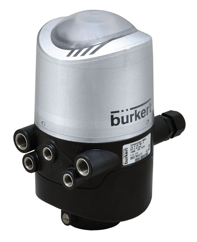
6.3 Type label (example)
Device designation/Type
Device design, number of solenoid
Electrical valves
connections Permitted pressure range
(cable glands) Permitted temperature range CE
Serial number S/N
ID number / Production details
Barcode
Pneumatic
Lead seal lug connections In addition to the CE Mark for EU conformity, the type label also shows
symbols for approvals according to ATEX Directives, FM (Factory
Mutual) or UL (for Canada and USA) if these apply to the respective
Shoulder screws (2 x M5) - no sealing function, merely as device.
protection against being pulled off the hub flange
Further details can be found in the operating instructions for Type 8681.
Fig. 1: Structure
english 9Type 8681
Technical data
6.4 Operating conditions (quality class 3) Min. 10 °C below the lowest operating
Standard version: temperature
Ambient temp.: -10 ... +55 °C Oil content
Degree of protection: IP65 / IP67 according to EN 60529 or (quality class X) Max. 25 mg/m3
IP69K according to IEC 40050-9 Temperature range of compressed air: -10 ... +50 °C
Version for use in an explosive atmosphere, Zone 2:
Pressure range: 2.5 ... 8 bar
Ambient temp.: +5 ... +55 °C
Air flow rate
Degree of protection: IP64 according to EN 60529 and
solenoid valve: 110 IN/min (for deaeration, aeration, ventilation)
requirements EN 60079-0: 2009
(110 IN/min - supplied state
When used in an explosive atmosphere (Zone 2), the devices must 200 IN/min - max. typical flow)
be installed in a protected installation location according to (QNn value according to definition for pressure
IEC/EN 60079-0. drop from 7 to 6 bar absolute at +20 °C)
6.5 Mechanical data Connections: Intake and exhaust air port G1/4
Working ports G1/8
Dimensions: See data sheet
Housing material: Outside: PA, PC, PPO, VA
6.7 Position measuring system data
Inside: ABS, PA, PMMA
Stroke range: 0 ... 80 mm
Sealing material: Outside: CR, EPDM
Resolution: ≤ 0.1 mm
Inside: EPDM, FKM, NBR
Total fault: ± 0.5 mm (when using a suitable target)
6.6 Pneumatic data
Control medium: Air, neutral gases: Air, neutral gases 6.8 Electrical data
Quality classes according to ISO 8573-1 See chapter: “8 24 V DC design”,
(5 µm filter recommended) “9 AS-I design”,
Dust content Max. particle size 40 μm, “10 DeviceNet design”,
(quality class 7) Max. particle density 10 mg/m3 “11 120 V AC design”,
Water content Max. pressure dew point -20 °C or “12 büS / CANopen design”.
10 englishType 8681
Assembly / Installation
7 ASSEMBLY / INSTALLATION 7.2 Assembly
For the assembly of the control head Type 8681 to a process valve,
7.1 Safety instructions
you will require a process valve-specific hub flange as an adapter.
DANGER! The hub flange must be adapted to the design of the process valve.
Risk of injury due to high pressure in the system! →→Mount the piston rod with the target on the process valve spindle.
`` Turn off the pressure and vent the lines before loosening lines Observe reference dimensions!
or valves. →→Fasten the hub flange on the process valve. During this, observe
Risk of explosion in an explosive atmosphere (explosive central alignment and sealing conditions!
atmosphere only in the event of a fault, since it is Zone 2)! →→Check the secure fit of the sealing rings (in the upper and the
`` Opening the hood or the housing in an explosive atmosphere is lower groove).
only permitted when the device is isolated! →→Mount the control head on the hub flange (infinitely 360° rotatable).
WARNING!
→→Secure the control head with the two locking screws (shoulder
screws M5, tightening torque: max. 3.2 Nm) in the middle groove of
Risk of injury due to electric shock! the hub flange against unintentional removal (not fixed into position!
– see “Fig. 1” or operating instructions, chapter “Assembly”).
`` Before reaching into the device or the equipment, switch off the
power supply and secure to prevent reactivation!
`` Observe the applicable accident prevention and safety regulations
for electrical equipment! 7.3 Pneumatic installation
Risk of injury due to improper assembly! →→Connect the required working connections 2/A1 to 2/A3 (each
`` Assembly may only be carried out by authorised specialist per- according to model) with the corresponding connections on the
sonnel and using the appropriate tools. process valve - see “Fig. 2” or in the operating instructions for
Risk of injury due to unintentional activation of the system Type 8681.
and uncontrolled restart! →→Connect the supply line to supply pressure connection 1/P
`` Secure system against unintentional activation! (2.5 … 8 bar).
`` Following assembly, ensure a controlled restart. →→A silencer has already been mounted on the exhaust air port (3/R)
in the supplied state.
english 11Type 8681
Assembly / Installation
7.4 Opening/Closing the housing
Lead seal
Opening:
lugs at
the housing →→Remove lead seal if housing is secured.
→→Open the plastic hood by turning it anticlockwise (all the way,
approx. 1.5 cm).
3/R 1/P
Exhaust air port Supply pressure Closing:
(silencer) connection
→→Put the plastic hood on the lower part such that the inner “lugs” are
positioned over the locking grooves and the external sealing lugs
are positioned almost over each other. Press the hood completely
over the seal of the lower part (see “Fig. 1”).
2/A3: SV 3 2/A2: SV 2 2/A1: SV 1 →→Turn the hood by approx. 1.5 cm clockwise (meaning until the
2/A1 ... A3 - working ports of solenoid valves (SV) sealing lugs are positioned over each other).
Fig. 2: Pneumatic connections A lead seal is required on the hood in potentially explosive
atmospheres!
The flow restriction screws R and P
of the solenoid valves (see operating open closed 7.5 Electrical installation
instructions) are used for setting the air
intake and exhaust for the working ports See chapter: “8 24 V DC design”,
R “9 AS-I design”,
(for setting of the control speed of the
process valves). “10 DeviceNet design”,
P “11 120 V AC design”,
“12 büS / CANopen design”.
Fig. 3: Flow restriction screws of the
solenoid valves
12 englishType 8681
24 V DC design
8 24 V DC DESIGN Solenoid valves:
Typ. switching capacity 0.9 W (per solenoid valve, for 200 ms
8.1 Connection options after switching on)
Typ. continuous output 0.6 W (per solenoid valve, from
200 ms after switching on)
Current consumption for
each solenoid valve: 50 mA at 12 V DC
25 mA at 24 V DC
22 mA at 28 V DC
Operating mode: Continuous operation (100% duty cycle)
Central display of the switching statuses:
ca. 42 mA with a power supply of
Connection left: Connection left: 24 V DC per illuminated display shown
1 x M16 x 1.5 cable gland for 1 x M16 x 1.5 cable gland with Outputs/Binary
power supply and signals multipole connection (M12 plug feedback signals: S1 out - S4 out
according to IEC 61076-2-101, Design: Normally open contact,
12-pole) on a cable of 8 cm PNP output; short-circuit protection,
Switchable
Connection right: Connection right:
output current: Max. 100 mA per feedback signal
1 x M16 x 1.5 cable gland for 1 x M16 x 1.5 cable gland for
external initiator external initiator Input/Proximity switch (external initiator: S4 in):
Power supply: Applied voltage at the control
head - 10%
8.2 Electrical data Current carrying capacity
Power supply: 12 ... 28 V DC, residual ripple 10% Sensor supply: Max. 90 mA; short-circuit protection
Design: DC 2 and 3 wire, NO or NC;
Power consumption PNP output
(standby current): 30 mA at 24 V DC
Inputs valve control (Y1 - Y3):
Signal level - active: U > 10 V, max. 24 V DC + 10%
english 13Type 8681
24 V DC design
8.3 Electrical installation (24 V DC) Teach-In Service
DANGER! buttons T1-3 interface
Risk of explosion in an explosive atmosphere (explosive DIP switches for
Connection colour coding the
atmosphere only in the event of a fault, since it is Zone 2)! with status LED Top LED
`` Opening the hood or the housing in an explosive atmosphere is for solenoid
only permitted when the device is isolated! valve V1
Connections
WARNING! Terminal with status LED
strip 1 for V2, V3
Risk of injury due to electric shock! Terminal strip 2
`` Before reaching into the system (except for the Teach-In procedure (external
in a non-explosive atmosphere) switch off the power supply and initiator)
secure it to prevent restarting!
`` Observe the applicable accident prevention and safety regulations Fig. 4: Electronic module (24 V DC)
for electrical equipment!
Risk of injury due to improper installation! Terminal strip 1 Assignment
`` Installation may only be carried out by authorised specialist per- 24 V Power supply 24 V
sonnel and using the appropriate tools.
GND GND
Cable gland: S1 OUT Output position S1
→→Open the housing. S2 OUT Output position S2
→→Prepare the connection cable for signals and power supply as well
S3 OUT Output position S3
as for the external initiator, if necessary.
→→Insert cables through the respective cable glands into the interior S4 OUT External initiator output S4
of the housing. Y1 Solenoid valve 1 input V1
→→Connect the wires to the terminal strips according to the pin Y2 Solenoid valve 2 input V2
assignments described in “Fig. 4”.
Y3 Solenoid valve 3 input V3
14 englishType 8681
24 V DC design
Terminal strip 2 Assignment Input and output signals to the higher-level control (PLC):
24 V Power supply 24 V DC for external initiator Pin 3 - S1 out Pin 2 - GND
S4 IN External initiator input
Pin 4 - S2 out
GND GND external initiator 11 Pin 1 - 24 V
10
→→Close the housing Pin 5 - S3 out
12 Pin 9 - Y3
→→Ensure IP protection (dummy plug) Pin 6 - S4 out
Cable gland with multipole connection:
Pin 7 - Y1 Pin 8 - Y2
Internal cabling work is not required for variants with multipole con-
nection. However, you will require the correspondingly packaged or Fig. 5: Multipole connection 24 V DC
assembled cable sets with the following pin assignment: (12-pole circular plug-in connector M12 x 1.0 - male according to
IEC 61076-2-101 — view onto the plug pins)
Pin Designation Assignment
1 24 V Power supply 24 V An external initiator can be connected via the triple terminal strip 2
2 GND GND (see “Fig. 4” or see operating instructions, chapter “Connecting an
external initiator”).
3 S1 OUT Output position S1
4 S2 OUT Output position S2
5 S3 OUT Output position S3
6 S4 OUT External initiator S4 output
7 Y1 Solenoid valve 1 input V1
8 Y2 Solenoid valve 2 input V2
9 Y3 Solenoid valve 3 input V3
10-12 Not assigned
english 15Type 8681
AS-I design
9 AS-I DESIGN 9.4 Electrical data
9.1 Connection options Power supply of the solenoid valves (SVs):
Setting the power supply of the solenoid valves using jumpers on
the AS interface electronic module.
Standard: Via AS-i Option: External
29.5 ... 31.6 V DC according to specification; (19.2 V DC to
21.0 ... 31.6 V DC according to specification 31.6 V DC)
Power24
Connection left:
1 x M16 x 1.5 cable gland with multipole connection (M12 plug
according to IEC 61076-2-101, 4-pole) to an 8 cm or 80 cm
long cable
Connection right: Input/Proximity switch (external initiator: S4 in):
1 x M16 x 1.5 cable gland for external initiator Power supply: Applied AS-i voltage at the
control head - 10%
9.2 Number of connectable control Current carrying capacity
heads Sensor supply: Max. 30 mA; short-circuit protection
In AS interface versions with extended addressing range (A/B slave), Design: DC 2 and 3 wire, NO or NC;
1 master can communicate with 62 slaves. PNP output
In AS interface versions with addressing range 31 slaves, a maximum Inputs: 3 binary feedback signals and
of 31 control heads can be connected to a bus line (the address range (from master perspective) 1 x external initiator
restriction).
Outputs (from master perspective) / Solenoid valve:
9.3 Bus line length Typ. switching capacity 0.9 W (per solenoid valve, for 200 ms
after switching on)
The bus cable may be a maximum of 100 m long. When designing the
Typ. continuous output 0.6 W (per solenoid valve, from 200 ms
system, consider the length of the round cable leading directly to the
after switching on)
control head (see example calculation in the operating instructions).
16 englishType 8681
AS-I design
Typ. pull-in current: 30 mA or 0.9 W per sol. valve / 200 ms 9.5 Electrical installation (AS-i)
Typ. holding current: 20 mA or 0.6 W per sol. valve
Operating mode: Continuous operation (100% duty cycle) WARNING!
Central display of the switching statuses: Risk of explosion in an explosive atmosphere (Zone 2)
Power consumption: ca. 33 mA or 1 W per illuminated display `` See DANGER note in chapter “8.3” on page 14!
shown (at 30.5 V AS-i voltage)
Risk of injury due to electric shock!
Power supply via AS interface bus: `` Before reaching into the system (except for the Teach-In procedure
Max. power consumption in a non-explosive atmosphere) switch off the power supply and
from AS-i:Type 8681
DeviceNet design
Power supply of the SVs 10 DEVICENET DESIGN
(via AS-i) (external) 10.1 Connection option
Pin Assignment Assignment Colour
1 AS-i+ AS-i+ brown Connection left::
1 x M16 x 1.5 cable gland with
2 not assigned GND white multipole connection (M12
3 AS-i- AS-i- blue plug according to IEC 61076-
4 not assigned 24 V+ black 2-101, 5-pole) to an 80 cm
long cable
An external initiator can be connected via the 3-way terminal strip “INI”
- see operating instructions, chapter “Connecting an external initiator”. Connection right:
1 x M16 x 1.5 cable gland for
external initiator
10.2 DeviceNet specification
EDS file 8681.EDS
Icons 8681.ICO
Baud rate Factory setting 1
25 kbit/s
Address Factory setting: 63
Process data 2 static input assemblies (input: from control head
to DeviceNet master/scanner)
1 static output assembly
Inputs 3 discrete feedback signals from the position
measuring system (positions S1 - S3)
1 discrete feedback signal from the external
initiator (S4)
1 analog position signal in mm
18 englishType 8681
DeviceNet design
Supply via DeviceNet string 10.4 Electrical data
(11 ... 25 V DC) Power supply: 11 … 25 V DC (according to
High signal switch level ≥ 5 V specification)
Low signal switch level ≥ 1.5 V
Max. power consumption: 6.5 mA, limited
Baud rate Thick cable Mid cable Thin cable internally to 10 mA
125 kbit/s 500 m 300 m 100 m Input voltage 1 signal: USensor > 10 V
Input current 0 signal: ISensor < 4 mA
250 kbit/s 250 m 250 m 100 m
Input voltage 0 signal: USensor < 5 V
500 kbit/s 100 m 100 m 100 m
Inputs (from master perspective) / Binary or analog feedback
The maximum drop line length is as follows for: signals:
The recovery of the 3 valve positions reported back in binary format
Baud rate Drop line Sum (in the network) or the analog position signal is described in the operating instruc-
125 kbit/s 6m 156 m tions in chapter “Position measuring system”.
250 kbit/s 6m 78 m
Outputs (from master perspective) / Solenoid valves:
500 kbit/s 6m 39 m Typ. switching capacity 0.9 W (per solenoid valve, for 200 ms
after switching on)
english 19Type 8681
DeviceNet design
Typ. continuous output 0.6 W (per solenoid valve, from WARNING!
200 ms after switching on)
Current consumption for Risk of injury due to electric shock!
each solenoid valve: 50 mA at 12 V DC `` Before reaching into the system (except for the Teach-In procedure
25 mA at 24 V DC in a non-explosive atmosphere) switch off the power supply and
22 mA at 28 V DC secure it to prevent restarting! Observe the applicable accident
prevention and safety regulations for electrical equipment!
Power reduction Integrated via DeviceNet interface
electronics Risk of injury due to improper installation!
`` Installation may only be carried out by authorised specialist per-
Typ. pull-in current 120 mA / 200 ms
sonnel and using the appropriate tools.
(3 valves)
Typ. holding current 100 mA at 24 V DC Internal cabling work is not required for variants with multipole con-
(3 valves) nection. However, you will require the correspondingly packaged or
Operating mode Continuous operation (100% duty cycle) assembled cable sets with the following pin assignment:
Central display of the switching statuses: View of plug from the front onto the pins:
Power consumption from
Pin 4: CAN_H Pin 3: V–
DeviceNet at 24 V DC Approx. 42 mA or 1 W per illuminated
display shown Pin 5: CAN_L
Pin 2: V+
Pin 1: Drain
10.5 Electrical installation (DVN)
Fig. 7: Multipole connection DeviceNet
DANGER!
Pin Assignment Colour
Risk of explosion in an explosive atmosphere (explosive 1 Drain (shielding)
atmosphere only in the event of a fault, since it is Zone 2)!
2 V+ red
`` Opening the hood or the housing in an explosive atmosphere is
only permitted when the device is isolated! 3 V- black
4 CAN_H white
5 CAN_L blue
20 englishType 8681
DeviceNet design
An external initiator can be con- 10.8 Configuring process data
nected via the 3-way terminal strip To transmit process data via an I/O connection, 2 static input assem-
- see operating instructions, chapter blies and 1 static output assembly can be selected - for details, see
“Connecting an external initiator”. operating instructions, chapter “Configuring process data”.
“Address” in the table describes the data attribute of the assemblies
for read access (class, instance, attributes).
Input assemblies Address Format of the data attribute
Value 0: OFF / Value 1: ON
10.6 Network topology S1…S4 4, 1, 3 Byte 0:
When installing a DeviceNet system, ensure that the terminating circuit Bit 0: Position S1
of the data lines is correct. The circuit prevents the occurrence of Bit 1: Position S2
(Factory setting)
interference caused by signals reflected onto the data lines. Bit 2: Position S3
Bit 3: Position S4
The trunk line must be terminated at both ends with resistors of
120 Ohm each and 1/4 W power loss (see operating instructions, S1…S4 + POS 4, 2, 3 Byte 0:
chapter “Network Topology DeviceNet”). Bit 0: Position S1
Bit 1: Position S2
(with POS: Actual Bit 2: Position S3
position) Bit 3: Position S4
10.7 Configuring the baud rate and DVN
Bit 4…7: Not used
address
Byte 1:
Eight DIP switches are available for configuration:
POS in mm
• DIP switches 1 to 6 for the DeviceNet address “Address” in the table describes the data attribute of the assemblies
(Factory setting: 63, i.e. DIP 1 - 6: on) for read access (class, instance, attributes).
• DIP switches 7 to 8 for the baud rate
(Factory setting: 125 kbit/s, i.e. DIP 7 + 8: off)
Further settings - see operating instructions, chapter “Configuring the
DeviceNet address / baud rate”.
english 21Type 8681
120 V AC design
Output assembly Address Format of the data attribute 11 120 V AC DESIGN
Value 0: OFF / Value 1: ON
11.1 Connection option
Solenoid valve 4, 21, 3 Byte 0:
V1 ... 3 Bit 0: V1 Connection left::
Bit 1: V2 1 x M16 x 1.5 cable gland for power
Bit 2: V3 supply and signals
Bit 3…7: Not used
Connection right:
10.9 Safety position of the solenoid 1 x M16 x 1.5 cable gland for external
initiator
valves in the event of a bus error
If the bus fails, the solenoid valve is switched to a programmable safety
position (default: the solenoid valve is in the power-off state) - for
11.2 Electrical data
details, see operating instructions, chapter “Configuring the device”.
Central power supply: 110 ... 130 V AC, 50/60 Hz
Bus failure is indicated via the central multi-colour status display
Power consumption
(for detailed information on the colour and blinking pattern - see oper-
(standby current): 10 mA at 120 V AC
ating instructions, chapter “Blinking pattern / Fault signaling”).
The bus status LED “Network” on the electronic module also indicates Solenoid valves:
whether a bus error has occurred - see operating instructions, chapter Max. switching capacity 1.7 VA (per solenoid valve)
“Display of the status LEDs in the event of a bus failure” or “Status of Typ. continuous output 1.4 VA (per solenoid valve)
the bus status LED “Network””. Power consumption: 12 mA at 120 V AC (per solenoid valve)
Operating mode: Continuous operation (100% duty cycle)
Central display of the switching statuses:
13 mA with a power supply of
120 V DC per illuminated display
shown
22 englishType 8681
120 V AC design
Outputs/Binary 11.3 Electrical installation
feedback signals: S1 out - S3 out
Design: NO contact, L switching, short-circuit WARNING!
protection via automatically resetting
Risk of explosion in an explosive atmosphere (Zone 2)
fuse
Switchable output `` See DANGER note in chapter “8.3” on page 14!
current: Max. 50 mA per feedback signal Risk of injury due to electric shock (120 V AC)!
Output voltage `` When setting the position measuring system (Teach-In), do not
- active: ≥ (operating voltage - 2 V) contact any live components!
Output voltage `` Before reaching into the system (except for the Teach-In procedure
- inactive: Max. 1 V in unloaded state in a non-explosive atmosphere) switch off the power supply and
secure it to prevent restarting!
Feedback signal output: S4 out is directly connected to S4 in `` Observe the applicable accident prevention and safety regulations
for electrical equipment!
Input / Proximity switches (external initiator: S4 in):
Risk of injury due to improper installation!
Power supply: Applied voltage at control
head UNominal = 120 VAC, 50/60 Hz `` The PE connection must be connected!
`` Installation may only be carried out by authorised specialist per-
Design: DC 2 and 3 wire, sonnel and using the appropriate tools.
NO contact, L-switching
Input current 1 signal: ISensor < 2 mA
Inputs valve control (Y1 - Y3): Cable gland:
Signal level - active: U > 60 V AC →→Open the housing.
Signal level - inactive: U < 20 V AC →→Prepare the connection cable for signals and power supply as
Impedance: > 40 kOhm well as for the external initiator, if necessary.
→→Insert cables through the respective cable glands into the interior
of the housing.
→→Connect the wires to the terminal strips according to the pin
assignments described in “Fig. 8”.
english 23Type 8681
120 V AC design
Connec- Teach-In Terminal strip 2 Assignment (external initiator)
tion with buttons T2, L Power supply - conductor
status LED T3, T1
S4 IN External initiator input
for SV1 Connections
with status LED N Power supply - neutral conductor
Service for SV2, 3
interface →→Close the housing.
DIP switches →→Ensure IP protection (dummy plug)
for colour
coding the
Top LED An external initiator can be connected via terminal strip 2 - see
Terminal
strip 1
operating instructions, chapter “Connecting an external initiator”.
Terminal
strip 2 (exter-
nal initiator)
Fig. 8: Electronic module (120 V AC)
Terminal strip 1 Assignment
PE Protection earth - protective conductor
L Conductor
Power supply 120 V AC
N Neutral conductor
S1 OUT Output position S1
S2 OUT Output position S2
S3 OUT Output position S3
S4 OUT External initiator output S4
Y1 Solenoid valve 1 input V1
Y2 Solenoid valve 2 input V2
Y3 Solenoid valve 3 input V3
24 englishType 8681
büS / CANopen design
12 BÜS / CANOPEN DESIGN 12.1 Connection options
“büS” is a system bus developed by Bürkert with a communication
protocol based on CANopen. The description of the CANopen objects
(index / subindex) can be found in a separate document on the Bürkert
website (search for: Type / Downloads / Software).
The following explanations refer to the application of the e.g.
EtherNet/IP protocol using a Bürkert gateway preconfigured for a
maximum of 63 control heads. However, the following bus systems
are also supported by the Bürkert gateway: PROFINET, Modbus/TPC,
PROFIBUS DPV1, EtherCAT, CC-Link. Connection left::
1 x M16 x 1.5 cable gland without or with multipole connection
(M12 plug according to IEC 61076-2-101, 5-pole) to an 80 cm
After the electrical and pneumatic installation of the büS/CANopen
long cable for power supply and signals
control heads in the network (see chapter “7” and from “12.3”), perform
the following actions on the control heads: Connection right:
→→Addressing of the control heads (chapter “12.10”) 1 x M16 x 1.5 cable gland for external initiator
→→Setting the baud rate (chapter “12.10”)
12.2 Electrical data
→→When using büS/CANopen control heads in conjunction with
a (preconfigured) gateway: “Hiding” of non-existent devices Power supply: 11 … 25 V DC
(chapter “12.5”) Power consumption
→→Sealing of unused connections (chapter “12.6”) (standby current):Type 8681
büS / CANopen design
Current carrying capacity Operating mode Continuous operation (100% duty cycle)
sensor supply: Max. 30 mA
Central display of the switching statuses:
Short-circuit protection
Power consumption from büS/CANopen
Design: DC 2 and 3 wire,
at 24 V DC 30 mA at 24 V DC per illuminated
normally open contact,
display shown
PNP output
Input current 1 signal: ISensor > 6.5 mA, limited internally to 10 mA
Input voltage 1 signal: USensor > 10 V 12.3 Electrical installation
Input current 0 signal: ISensor < 4 mA
Input voltage 0 signal: USensor < 5 V WARNING!
Inputs (control head –> gateway/PLC) / Binary or analog
Risk of injury due to electric shock!
feedback signals:
The recovery of the 3 valve positions reported back in binary format `` Before reaching into the system, switch off the power supply and
secure it to prevent restarting! Observe the applicable accident
or the analog position signal is described in the operating instructions prevention and safety regulations for electrical equipment!
in chapter “Position measuring system”. The analog target position
signal (resolution: 0.1 mm) is available as acyclical value/parameter in
the büS/CANopen network. WARNING!
Outputs (gateway/PLC –> control head) / solenoid valves Risk of injury due to electric shock!
(Type 6524):
Risk of injury due to improper installation!
Typ. switching capacity 0.9 W (per solenoid valve, for 200 ms)
after switching on) `` Installation may only be carried out by authorised specialist per-
sonnel and using the appropriate tools.
Typ. continuous output 0.6 W (per solenoid valve, from
200 ms after switchin on)
Power reduction integrated via büS/CANopen interface The electrical installation is carried out as described in more detail in
electronics chapter “8.3 Electrical installation (24 V DC)” on page 14 while taking
Typ. pull-in current 38 mA or 0.9 W / 200 ms at 24 V DC into account “Fig. 9” and the pin assignments listed below:
(per each solenoid valve)
Typ. holding current 25 mA or 0.6 W at 24 V DC (per each
solenoid valve)
26 englishType 8681
büS / CANopen design
Teach-In Service Cable gland with multipole connection:
buttons T1-3 interface Internal cabling work is not required for variants with multipole con-
Connection nection. However, you will require the correspondingly packaged or
DIP switches for assembled cable sets with the following pin assignment:
with status LED for
colour coding
solenoid valve V1
the Top LED View of plug from the front onto the pins:
DIP switches for
address and baud Pin 4: CAN_H (white) Pin 3: V– (black)
Connections with
rate status LED for Pin 5: CAN_L (blue)
Status LEDs solenoid Pin 2: V+ (red)
valves V2, V3 Pin 1: Drain (shielding)
Terminal strip 1
power supply Terminal strip 2 Fig. 10: Multipole connection büS/CANopen
büS/CANopen (external initiator)
and bus signals An external initiator can be connected via the triple terminal strip 2
(see “Fig. 9” or see operating instructions, chapter “Connecting an
Fig. 9: Electronic module (büS/CANopen) external initiator”).
Terminal strip 1 Assignment
12.4 büS/CANopen specification
Baud rate Factory setting: “software-configurable”
V+ Power supply büS/CANopen
(initial setting: 500 kbit/s)
V- Power supply büS/CANopen
Address Factory setting: “0” = “software-configurable”
CAN_H Bus signal CAN high (initial setting: self-addressing of the node ID)
CAN_L Bus signal CAN low Bus mode Factory settings: büS (“software-configurable” only)
Terminal strip 2 Assignment
Process data 6 byte input (büS/CANopen) – input: from control
V+ Power supply for external initiator head Type 8681büS to gateway/PLC
S4 IN External initiator input 1 byte output (büS/CANopen)
1 (to 6) byte input (EtherNet/IP; depending on config.)
GND GND external initiator 1 byte output (EtherNet/IP)
english 27Type 8681
büS / CANopen design
Inputs 6byte: 4 byte „analog“ cyclic position feedback of the 12.6 Network principles
target, 1 byte NAMUR state feedback , 1 byte for Several aspects must be considered when installing a büS/CANopen
3 discrete feedback signals from the position mea- fieldbus system.
suring system (positions S1 - S3) + 1 discrete
feedback signal from the external initiator (S4); • Each “node” requires its own “node ID”, each gateway can control up
Power supply via büS/CANopen cable to 63 “nodes” (max. number applies to control heads Type 8681 büS).
(11 ... 25 V DC) • The CAN cable must be “terminated” at both ends: Terminate the
(The acyclic analog position signal of the target end of the CAN cable with a terminating resistor (120 Ω) or, if the
can be read out e.g. as parameter „8681_Current_ cable ends at a distribution box, connect the terminating resistor to
Position_mm_DevXX“ (resolution: 0.1 mm)). the CAN OUT connection.
Outputs 1 byte for control of the 3 solenoid valves • If the voltage loss is too high, an additional power supply must be
fed into a distribution box (PWR IN connection).
Configurations for other bus systems upon request. • Observe baud rates and maximum cable lengths (see “12.7”)
• A PC with Bürkert Communicator Type 8920 can be connected for
service work and also for reading CAN data.
12.5 Network configuration
• Required tightening torque for all M12 plug-in connections (cables,
The Type 8681 büS/CANopen control heads are preferably operated T-pieces, ...) to ensure the necessary seal tightness against moisture:
with a (preconfigured) ME43 Gateway. 0.6 Nm + 0.1 Nm.
Installation, registration, changing the IP address (e.g. using Bürkert • Seal all open connections tightly with protective caps!
Communicator, LogixDesigner, etc.) are described in detail in the
Further details - see “Additionals to 8681 (büS)”.
„Additionals to 8681 (büS)“.
The configuration of the entire network (consisting of gateway, PLC,
control heads) using Bürkert Communicator or LogixDesigner, e.g. the
12.7 Bus line length
„Hide“ function and the reading/writing of cyclic and acyclic parameters, The maximum total line length (sum of trunk lines and drop lines) of a
is also described there – as an example for EtherNet/IP. network depends on the baud rate.
The appendix of the „Additionals to 8681 (büS)“ also contains several The maximum length of a single drop line is 6 m. The maximum
cabling examples. total line length and the maximum total length of all drop lines in total
(according to büS/CANopen specification) depending on the baud
rate (in kbit/s) is as follows for:
28 englishType 8681
büS / CANopen design
Baud rate Max. total length Max. total drop line length 12.9 I/O data (cyclic) and parameters
125 kbit/s 200 m 100 m (acyclic)
250 kbit/s 100 m 55 m Each control head has 6 byte of input data and 1 byte of output data
500 kbit/s 40 m 30 m (bit-coded): Position feedback S1 ... S4 and solenoid valve switching
statuses V1 ... V3. In LogixDesigner, these can, e.g., be found as
“controller tags”.
12.8 Bus error / Safety position of the
solenoid valves Further, i.e. acyclic, data/parameters are listed together with configured
fieldbus addresses in a parameter list and can be downloaded from the
Bus failure is indicated via the central multi-colour device status display homepage (search for: Ident no. of configured gateway / Downloads /
(Top LED). The bus status LED “Network” on the electronic module Software (ZIP container)).
(“Fig. 9”) also indicates whether a bus error has occurred without
differentiating between special blinking patterns.
Bus errors can be caused, for example, by communication problems 12.10 Configuring the baud rate and
with the gateway or PLC, incorrect addressing of node IDs, incorrect node ID (büS/CANopen address)
baud rate.
Eight DIP switches are available for configuration (see “Fig. 9” and
Safety position of the solenoid valves in the event of a bus error chapter “12.4”):
If the bus fails, the solenoid valves are switched to a programmable
safety position (default: The solenoid valve is in the power-off state). For • DIP switches 1 to 6: For the büS/CANopen address (node ID)
details on the configuration - see “Additionals to 8681 (büS)” (chapter Factory setting: 0 (software-configurable, initial setting:
“Safety position in case of bus failure”). auto addressing),
i.e. DIP 1 - 6: off
• DIP switches 7 to 8: For the baud rate
Factory setting: software-configurable (initial setting:
500 kbit/s), i.e. DIP 7 + 8: on
For details and special information - see “Additionals to 8681 (büS)”.
english 29Type 8681
Position measuring system
13 POSITION MEASURING SYSTEM →→If required, return control head and system to normal state
(switching position, power supply).
The recordable stroke range is between 0 ... 80 mm.
→→Close the housing.
Three Teach-In buttons have been provided for comparison with the
actual stroke range. The position feedback is given as S1, S2, S3.
13.2 Teach reset
For the büS/CANopen design: The indication of position feedback
and (error) states by the device status LED/Top LED can vary depending
→→Depress the Teach-In buttons (T1 + T2) for approx. 2.5 sec.
(optical feedback: Flashing in the fault colour)
on the selected display mode - see „Additionals to 8681 (büS)“.
13.3 Autotune
13.1 Teach-In
Autotune functions and Autotune sequences - see operating instructions.
→→Open the housing (but not in an explosive atmosphere!).
→→Establish power supply. 13.4 LED – colour assignments
→→Position the process valve at the lower switching position. The color combinations will be defined via the DIP switches for colour
→→Depress the lower Teach-In button (T1) for approx. 1.5 seconds coding – see “Fig. 4”, “Fig. 8”, “Fig. 9”). In the delivery state, the fol-
(the corresponding LED will flash quickly three times). When this lowing position feedback is defined:
position S1 has been saved, the corresponding LED will remain S1 - green, continuously lit,
continuously lit until the position of the piston is changed.
S2 - yellow, continuously lit,
→→Afterwards, position the process valve at the upper switching
position to be recorded. S3 - green, continuously flashing (250 ms/250 ms)
→→Depress the upper Teach-In button (T2) for approx. 1.5 seconds It is also possible to set different colour combinations with the help of
(the corresponding LED will flash quickly three times). When this the DIP switches - see operating instructions, chapter “Setting the
position S2 has been saved, the corresponding LED will remain colour combinations”.
continuously lit until the position of the piston is changed. In the event of a fault, the Top LED flashes in differently coded blinking
→→The process valve can now be moved into a third, defined patterns - see operating instructions, chapter “Blinking pattern/Fault
position. signaling”.
→→Depress the middle Teach-In button (T3) for approx. 1.5 seconds If various signals overlap, there are feedback priorities - see operating
(the corresponding LED will flash quickly three times). When this instructions, chapter “Signal priorities”.
position S3 has been saved, the corresponding LED will flash For the büS/CANopen design: There are further setting options
continuously until the position of the piston is changed. for colors, display modes, blinking patterns, signal priorities – see
„Additionals to 8681 (büS)“.
30 englishType 8681
Start-up
14 START-UP 15 TRANSPORTATION, STORAGE,
WARNING! DISPOSAL
NOTE!
Risk of injury from improper operation!
Storage / Transport damage!
Improper operation may result in injuries as well as damage to the
device and the area around it. Inadequately protected devices may be damaged during transpor-
`` Before start-up, ensure that the operating personnel are familiar tation or storage.
with and completely understand the contents of the operating `` Protect the device against moisture and dirt in shock-resistant
instructions. packaging during transportation/storage.
`` Observe the safety instructions and intended use. `` Prevent the temperature from exceeding or dropping below the
`` Only adequately trained personnel may start up the system/the permitted storage temperature.
device. `` Storage temperature: -20 … +65 °C.
→→Installation of the control head Type 8681 (see chapter “7” on NOTE!
page 11). Damage to the environment caused by device components
→→Pneumatic and electrical installation (see chapter “7.3”, “7.5”) contaminated with media.
→→Setting the position measuring system (Teach-In or Autotune) - `` Observe applicable disposal and environmental regulations.
see chapter “13” →→Dispose of the device and packaging in an environmentally
→→If Type 8681 with bus communication is used: Setting up the friendly manner.
network - see always from chapter “9.2” (AS-i), “10.2” (DeviceNet), →→Observe national waste disposal regulations.
“12.4” (büS/CANopen)
The control head is ready for operation after assembling, installing and
setting the position measuring system (and the network if necessary)
according to the Operating Instructions for “standard” Type 8681 or
the Additional Instructions for Type 8681 büS/CANopen.
english 31Typ 8681
Inhaltsverzeichnis
1 DER QUICKSTART........................................................................................ 34 7.2 Montage............................................................................................40
1.1 Begriffsdefinition „Gerät“ und „büS“..........................................34 7.3 Pneumatische Installation..............................................................40
1.2 Darstellungsmittel............................................................................34 7.4 Öffnen/Schließen des Gehäuses................................................41
7.5 Elektrische Installation....................................................................41
2 BESTIMMUNGSGEMÄSSE VERWENDUNG3����������������������������������� 35
8 24 V DC - AUSFÜHRUNG......................................................................... 42
3 GRUNDLEGENDE SICHERHEITSHINWEISE.................................. 35 8.1 Anschlussmöglichkeiten................................................................42
4 ALLGEMEINE HINWEISE........................................................................... 37 8.2 Elektrische Daten............................................................................42
8.3 Elektrische Installation (24 V DC)...............................................43
4.1 Kontaktadressen..............................................................................37
4.2 Gewährleistung...............................................................................37 9 AS-I - AUSFÜHRUNG................................................................................. 45
4.3 Informationen im Internet...............................................................37 9.1 Anschlussmöglichkeiten................................................................45
5 AUFBAU UND FUNKTION........................................................................ 37 9.2 Anzahl anschließbarer Steuerköpfe............................................45
9.3 Länge der Busleitung.....................................................................45
5.1 Handbetätigung...............................................................................37
9.4 Elektrische Daten............................................................................45
5.2 Aufbau................................................................................................38
9.5 Elektrische Installation (AS-i).......................................................46
6 TECHNISCHE DATEN................................................................................. 38
10 DEVICENET - AUSFÜHRUNG................................................................. 47
6.1 Konformität ......................................................................................38
10.1 Anschlussmöglichkeit..................................................................47
6.2 Normen..............................................................................................38
10.2 Spezifizierung DeviceNet............................................................47
6.3 Typschild (Beispiel).........................................................................38
10.3 Länge der Busleitung...................................................................48
6.4 Betriebsbedingungen.....................................................................39
10.4 Elektrische Daten..........................................................................48
6.5 Mechanische Daten........................................................................39
10.5 Elektrische Installation (DVN).....................................................49
6.6 Pneumatische Daten......................................................................39
10.6 Netztopologie.................................................................................50
6.7 Daten Wegmesssystem.................................................................39
10.7 Konfiguration von Baudrate und DVN-Adresse.....................50
6.8 Elektrische Daten............................................................................39
10.8 Konfiguration der Prozessdaten................................................50
7 MONTAGE / INSTALLATION.................................................................... 40 10.9 Sicherheitsstellung der Magnetventile bei Busfehler...........51
7.1 Sicherheitshinweise........................................................................40
32 deutschYou can also read