WIFI ClearView 7in1 EN Instruction manual DE Bedienungsanleitung - Weather Station Wetterstation - Bresser
←
→
Page content transcription
If your browser does not render page correctly, please read the page content below
Weather Station · Wetterstation ·

WIFI ClearView 7in1

EN Instruction manual
DE Bedienungsanleitung

Besuchen Sie unsere Website über den folgenden QR Code oder Weblink um weitere Informationen
DE      zu diesem Produkt oder die verfügbaren Übersetzungen dieser Anleitung zu finden.

        Visit our website via the following QR Code or web link to find further information on this product or
EN      the available translations of these instructions.

        Si vous souhaitez obtenir plus d’informations concernant ce produit ou rechercher ce mode
FR      d’emploi en d’autres langues, rendez-vous sur notre site Internet en utilisant le code QR ou le lien
        correspondant.

        Bezoek onze internetpagina via de volgende QR-code of weblink, voor meer informatie over dit
NL      product of de beschikbare vertalingen van deze gebruiksaanwijzing.

        ¿Desearía recibir unas instrucciones de uso completas sobre este producto en un idioma determinado?
ES      Entonces visite nuestra página web utilizando el siguiente enlace (código QR) para ver las versioneAs
        disponibles.

        Desidera ricevere informazioni esaustive su questo prodotto in una lingua specifica? Venga a
 IT     visitare il nostro sito Web al seguente link (codice QR Code) per conoscere le versioni disponibili.

                                                    www.bresser.de/P7002586

                   GARANTIE · WARRANTY · GARANTÍA · GARANZIA

www.bresser.de/warranty_terms

                                                                                                                     WORKS WITH:

APP DOWNLOAD:

                                                                                                                     AWEKAS
Weather Underground is a registered trademark of The Weather Channel, LLC. both in the United States and internationally. The Weather
Underground Logo is a trademark of Weather Underground, LLC. Find out more about Weather Underground at www.wunderground.com

Apple and the Apple logo are trademarks of Apple Inc., registered in the U.S. and other countries. App Store is a service mark of Apple Inc.,
registered in the U.S. and other countries. Google Play and the Google Play logo are trademarks of Google Inc.
English................................................................................................................... 4 Deutsch ................................................................................................................. 31
Table of contents
1 Imprint ............................................................................................................................................................. 6

2 Validity note .................................................................................................................................................... 6

3 About this Instruction Manual....................................................................................................................... 6

4 General safety instructions ........................................................................................................................... 6

5 Parts overview base station .......................................................................................................................... 8

6 Multisensor parts overview ........................................................................................................................... 9

7 Delivery content.............................................................................................................................................. 9

8 Screen display .............................................................................................................................................. 10

9 Before commissioning................................................................................................................................. 11

10 The first steps ............................................................................................................................................... 11

11 Establish power supply ............................................................................................................................... 11

12 Attaching rubber linings .............................................................................................................................. 12

13 Mounting and attaching the multi-function radio sensor ......................................................................... 12

14 Signal transmission ..................................................................................................................................... 13

15 Create a user account for Weather Underground (optional).................................................................... 13

16 Create user account for weathercloud (optional)...................................................................................... 13

17 Setting up an user account for other weather services (e.g. AWEKAS) ................................................. 14

18 Configuration / Setting up a WIFI connection............................................................................................ 14

19 Advanced settings........................................................................................................................................ 18

20 Automatic time setting................................................................................................................................. 19

21 Manual time adjustment............................................................................................................................... 19

22 Time zone setting ......................................................................................................................................... 19

23 Wake-up call setting..................................................................................................................................... 20

24 Snooze function............................................................................................................................................ 20

25 Rainfall........................................................................................................................................................... 20

26 Light intensity, UV index and sunburn time .............................................................................................. 21

27 Manual measurement display ..................................................................................................................... 22

28 Clima indication (indoor) ............................................................................................................................. 22

29 Moon phases................................................................................................................................................. 22

30 Weather trend ............................................................................................................................................... 23

31 Trend arrow indicators................................................................................................................................. 24

32 Barometric / Atmospheric Pressure ........................................................................................................... 24

33 Beaufort scale............................................................................................................................................... 24

34 ‘Feels like’ temperature................................................................................................................................ 25

4
35 Heat index ..................................................................................................................................................... 25

36 Dew point ...................................................................................................................................................... 26

37 History record for the past 24 hours .......................................................................................................... 26

38 Adjusting the display brightness................................................................................................................ 26

39 Viewing Live weather data with Weather Underground............................................................................ 26

40 Retrieve Weathercloud weather data.......................................................................................................... 27

41 Setup the station to transmit weather data to AWEKAS .......................................................................... 27

42 Troubleshooting ........................................................................................................................................... 27

43 EC declaration of conformity ...................................................................................................................... 28

44 UKCA Declaration of Conformity ................................................................................................................ 28

45 Warranty ........................................................................................................................................................ 28

46 Cleaning and maintenance .......................................................................................................................... 28

47 Disposal......................................................................................................................................................... 30

                                                                                                                                                                     5
1 Imprint
Bresser GmbH
Gutenbergstr. 2
46414 Rhede
Germany
www.bresser.de
For any warranty claims or service enquiries, please refer to the information on "Warranty" and "Ser-
vice" in this documentation. We apologize for any inconvenience caused by the fact that we cannot
process enquiries or submissions sent directly to the manufacturer's address.
Errors and technical changes excepted.
© 2021 Bresser GmbH
All rights reserved.
The reproduction of this documentation - even in extracts - in any form (e.g. photocopy, print, etc.) as
well as the use and distribution by means of electronic systems (e.g. image file, website, etc.) without
the prior written permission of the manufacturer is prohibited.
The designations and brand names of the respective companies used in this documentation are gen-
erally protected by trade, trademark and/or patent law in Germany, the European Union and/or other
countries.
2 Validity note
This documentation is valid for the products with the following article numbers:
7002586 7902586
Manual version: 0721
Manual designation:
Manual_7002586_WIFI-ClearView-7in1_en-de_BRESSER_v072021a
Always provide information when requesting service.
3 About this Instruction Manual
NOTICE
These operating instructions are to be considered a component of the device.
Read the safety instructions and the operating manual carefully before using this device.
Keep this instruction manual in a safe place for future reference. When the device is sold or given to
someone else, the instruction manual must be provided to the new owner/user of the product.
4 General safety instructions
DANGER
Risk of an electric shock!
This device contains electronic parts that are powered by a power source (AC adapter and/or batter-
ies). Improper use of this product may result in electric shock. Electric shock can cause serious or fatal
injuries. It is therefore imperative that you observe the following safety information.
6 / 60• Never leave children unattended when handling the device! Follow the instructions carefully and
do not attempt to power this device with anything other than power sources recommended in this
instruction manual, otherwise there is a danger of an electric shock!
• Disconnect the power supply by pulling the mains plug when the appliance is not in use, in case of
a longer interruption of operation and before any maintenance and cleaning work.
• Place your device so that it can be disconnected from the power supply at any time. The power
outlet should always be near your appliance and should be easily accessible, as the plug of the
power cord serves as a disconnect device from the mains supply.
• To disconnect the unit from the mains, always pull the mains plug and never pull the cable!
• Check this device, cables and connections for damage before use.
• Never attempt to operate a damaged device, or a device with damaged electrical parts! Damaged
parts must be replaced immediately by an authorized service agent.
• Operate the device only in a completely dry environment and do not touch the device with wet or
damp body parts.
DANGER
Danger of suffocation!
Improper use of this product may result in suffocation, especially for children. It is therefore imperative
that you observe the following safety information.
• Keep packaging materials (plastic bags, rubber bands, etc.) away from children! There is a danger
of choking!
• This product contains small parts that can be swallowed by children! Choking hazard!
DANGER
Explosion hazard!
Improper use of this product may result in fire. It is essential that you observe the following safety in-
formation in order to avoid fires.
• Do not expose the device to high temperatures. Use only the supplied AC adapter or the recom-
mended batteries. Do not short-circuit the device or batteries or dispose of in fire! Excessive heat
and improper handling can cause short circuits, fires and even explosions!
NOTICE
Danger of material damage!
Improper handling may result in damage to the unit and/or accessories. Therefore, use the device only
in accordance with the following safety information.
• Do not disassemble the device! In the event of a defect, please contact your dealer. They will con-
tact the Service Center and can arrange the return of this device for repair if necessary.
• Do not expose the device to high temperatures and protect it from water and high humidity.
• Do not immerse the unit in water!
• Do not subject the device to excessive vibrations.
• Only use accessories and spare parts for this device that comply with the technical specifications.
• Use only the recommended batteries. Always replace weak or empty batteries with a new, com-
plete set of batteries at full capacity. Do not use batteries from different brands or types or with dif-
ferent capacities. Remove batteries from the device if it is not to be used for a longer period of
time!
• Do not use rechargeable AA batteries, as these will not give out the correct voltage for use.
7 / 60NOTICE
Danger of voltage damage!
The manufacturer accepts no liability for voltage damage as a result of incorrectly inserted batteries,
or the use of an unsuitable mains adapter!
5 Parts overview base station
23 21 19
9 24 22 20
A
1 10
B
25
2 4 5 7 11 13 15 17
3 6 8 12 14 16 18
Illustration 1: All parts of the base station
1 Display 2 CHANNEL button (outdoor sensor channel se-
lection)
3 HISTORY button (recall recorded measure- 4 MAX/MIN button (recall of recorded high/low
ment data) values)
5 WIND button 6 SUN button
7 BARO button 8 RAIN button
9 ALARM/SNOOZE button 10 Ventilation slits
11 Stand (fold-out) 12 WIFI/SENSOR button
13 REFRESH button 14 [ °C / °F ] button
15 Power jack 16 RESET button
17 Battery compartment (backup power supply) 18 HI/LO/AUTO selector switch
19 UP/contrast button 20 DOWN/NDX button
21 Wall mount fixture 22 ALERT button (HI/LO alarm settings)
23 ALARM button (alarm time setting) 24 CLOCK SET button (time and user-defined
settings)
25 Power adapter
8 / 606 Multisensor parts overview
1 10
11
2
3 6 12
7
C
13
8
F
9
4
D
14
15
5
E 16
Illustration 2: All parts of the multisensor
1 Antenna 2 Rain gauge
3 UV sensor 4 Mounting bar
5 Mounting shoe 6 Circular level
7 Wind cups (wind speed) 8 Thermo-/Hygrometer
9 Wind vane (wind direction) 10 LED function indicator
11 RESET Knob 12 Battery compartment cover
13 Mounting clamp (pipe clamp) 14 Rain sensor
15 Tipping bucket 16 Drain holes
7 Delivery content
Base station (A), power adapter (B), multifunctional outdoor sensor (C), mounting rod (D), mounting
shoe (E), pipe clamp (F), screws, instruction manual
Also required (not included in delivery):
3 x 1.5V batteries type AA/LR6 (outdoor sensor)
Backup battery (not included in delivery):
1 x button cell type CR2032 (Base station)
9 / 608 Screen display
1 4 5 7 10
2 3 6 8 9
32 11
31 12
30 13
29
28 14
15
27
26 22 20
25 24 21 18 17 16
23 19
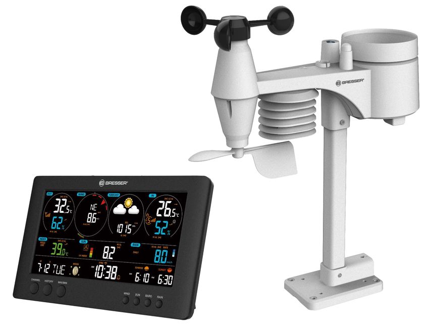
Illustration 3: Screen display of the base station
1 Symbol for active high (HI) or low (LO) alarm 2 Trend arrow (steady, rising or falling)
(outdoor)
3 Wind speed value 4 Wind direction (named)
5 Wind direction (graphical) 6 Air pressure value
7 Weather Forecast (12~24 hours) 8 Air pressure alarm
9 Interior sensor channel and signal reception 10 Symbol for active high (HI) or low (LO) alarm
strength icon (indoor)
11 Internal temperature (station or sensor) 12 Indoor climate indicator
13 Air humidity (indoor) 14 Rain rate (graphical)
15 Precipitation value 16 Sunset time
17 Sunrise time 18 UV value
19 Symbol for enabled alarm 20 Symbol for WIFI connection status and Inter-
net time synchronization
21 Current time or alarm time (hours:minutes) 22 AM/PM information in 12-hour time mode
23 UV index (graphical) 24 Moon phase (graphical)
25 Weekday 26 Date (month-day or vice versa)
27 Temperature value according to the selected 28 Weather index (feels like, dew point, heat,
weather index wind chill)
29 Wind force (classification according to 30 Air humidity (outdoor)
Beaufort)
31 Multifunction outdoor sensor: Symbol for the 32 Outdoor temperature
signal reception strength of the multifunction
sensor
10 / 609 Before commissioning
NOTICE
Avoid connection faults!
In order to avoid connection problems between the devices, the following points must be observed
during commissioning.
1. Place the base unit (receiver) and sensor (transmitter) as close together as possible.
2. Connect the power supply to the base unit and wait until the indoor temperature is displayed.
3. Establish power supply for the sensor.
4. Set up/operate the base unit and sensor within the effective transmission range.
5. Make sure that the base unit and the radio sensor are set to the same channel.
When changing the batteries, always remove the batteries in both the base unit and the sensor and
reinsert them in the correct order so that the radio connection can be re-established. If one of the two
devices is operated via a mains power connection, the power connection for this device must also be
disconnected briefly when changing the battery. If, for example, only the batteries in the sensor are re-
placed, the signal cannot be received or can no longer be received correctly.
Note that the actual range depends on the building materials used in the building and the position of
the base unit and outdoor sensor. External influences (various radio transmitters and other sources of
interference) can greatly reduce the possible range. In such cases, we recommend finding other loca-
tions for both the base unit and the outdoor sensor. Sometimes a shift of just a few centimetres is
enough!
10 The first steps
Follow the bullet points in order, to ensure a successful setup.
1. Setting up power supply (base station and wireless sensor)
2. Mount the wireless sensor
3. The base station is now in AP mode (LED flashes green) and ready for initial setup.
4. Create an account with a weather service provider compatible with your station, e.g. wunder-
ground.com or weathercloud.net and add the station to your account ("My Profile" / "Add Weather
station") or ("Devices" / "+ New"). Make a note of the station ID and password, as they will be
needed in the next step.
5. Setting up the base station (Estabish WIFI / Router connection)
6. Viewing weather data via web, mobile or tablet
11 Establish power supply
Base unit
1. Insert the DC plug into the connection socket on the base unit.
2. Insert the Euro plug into the mains power socket.
3. The device is powered on directly.
Installing the backup battery:
1. Remove the battery compartment cover.
2. Insert the battery into the battery compartment. Make sure that the battery terminals are correctly
aligned (+/-).
3. Replace the battery compartment cover.
11 / 60Wireless sensor
4. Remove the screw on the battery compartment cover with a suitable Phillips screwdriver and re-
move the battery compartment cover.
5. Insert 2 x AA size batteries into the battery compartment. Make sure that the battery terminals are
correctly aligned (+/-).
6. Replace and screw on the battery compartment cover.
12 Attaching rubber linings
Attach the supplied self-adhesive rubber pads to the clamps as shown to ensure a firmer fitting of the
mounting rod.
13 Mounting and attaching the multi-function
radio sensor
1 2
5
3 4
Depending on the desired location, the wireless sensor can be mounted in different ways.
NOTICE! During installation, always ensure that the upper part of the wind vane is at least 1.5
metres above the ground. Ensure an absolutely horizontal position when using the circular level
in the sensor head. The wind turbine must always point north.
Assembly on a vertical or horizontal wooden element
1. Slide one end of the assembly bar into the aperture below the sensor head.
12 / 602. Push a bolt through the hole and put the nut on the other side. Tighten the screw connection hand-
tight.
3. Depending on the desired orientation, slide the opposite end of the assembly bar into the aperture
for vertical or horizontal mounting of the assembly base.
4. Slide another screw through the bore hole of the assembly base and put on the nut on the oppos-
ite site. Tighten the screw connection by hand.
Place the assembly base with its bottom site first on a wooden element. Use 4 wood screws to tighten
it.
Assembly on a vertical or horizontal tube
Repeat steps 1 to 4 as before.
• Place the assembly base with its bottom site first on the tube. Push the tube bracket against the
tube from the opposite site.
• Slide 4 screws through the bore holes of the assemby base and through the bore holes of the tube
bracket on the other site.
• Put on the 4 nuts and tighten the screw connection by hand.
14 Signal transmission
The base station automatically connects to the multi outdoor sensor and (if available) to other wireless
sensors. You can also press the WIFI / SENSOR button to search directly for the sensors. If the con-
nection is successful, the outdoor symbol (OUT) and/or the channel will appear on the display.
Connection status display:
Connection status Display indication
Good signal Receiver symbol
Sensor is searched for Receiver symbol flashes
No signal for 48 hours Er' (Error) is displayed
Sensor battery low, good signal Battery symbol is displayed
15 Create a user account for Weather
Underground (optional)
1. Enter the following web address for the 'Weather Underground' service in the address bar of your
web browser: https://www.wunderground.com
2. Click on 'Join' to get to the registration page.
3. Enter your personal user data and click on 'Sign up'.
4. Follow the further setup steps.
5. Under the menu item 'Sensor Network' > 'Connect a Weather Station' your own weather station
can be added.
6. A 'Station ID' and a 'Station Key/Password' are automatically generated by the service, which are
needed for the following configuration of the weather station.
NOTICE! Use a valid e-mail address for registration. Otherwise the service can not be used.
16 Create user account for weathercloud
(optional)
1. Enter the following web address in the address bar of the web browser: https://weathercloud.net
2. Under 'Join us today' enter the personal user data and click on 'Sign up'.
13 / 603. After successful registration and verification of the e-mail address, select the menu item "Devices"
under the user account.
4. Click the '+New' link under 'Devices' and enter the device and location data in the 'Create New
Device' window to create a new device. Select the appropriate weather station under 'Model'. For
'Link type' select the option 'Pro Weather Link'.
5. A 'weathercloud ID' and a 'key' which are needed for the following configuration of the weather sta-
tion are automatically generated by the service. These can be reached via the account at weather-
cloud.net under Devices > Settings > Link.
NOTICE! Use a valid e-mail address for registration. Otherwise the service can not be used.
17 Setting up an user account for other weather
services (e.g. AWEKAS)
1. You have the possibility to use a weather service of a third party provider, as shown here with the
example of AWEKAS.
2. Enter the following web address in the address bar of the web browser for the 'AWEKAS' service:
https://join.awekas.at
3. Fill in all the necessary information.
4. Make a note of the information: Username, Password, Geographic latitude (Latitude) in decimal
degrees (e.g. 48.30591), geographical longitude in decimal degrees (e.g. 14.2862).
NOTICE! Use a valid e-mail address for registration. Otherwise the service can not be used.
18 Configuration / Setting up a WIFI connection
1. At first start-up or by pressing the WIFI / SENSOR button for 6 seconds, the station switches to AP
mode. In this mode the ward is ready for WIFI setup.
2. The station now creates its own WIFI network to which you can connect to your smartphone or
computer. Search and connect to the SSID of the WIFI station (example: PWS-XXXXXX)
Illustration 4:
WIFI connection status:
14 / 601 2 3
1 Stable: Stable: The base station is connected 2 (6-7) will flash. Blinking: The base station is
to the WIFI router trying to establish a connection to the WIFI
router
3 (6-7) will flash. Console currently in Access
Point (AP) mode
3. Once you are successfully connected, open your Internet browser and enter the address
192.168.1.1 in the URL field.
4. Now enter your router data (SSID of your home WIFI router) and weather service data (station ID /
station key) and select the service for automatic time transmission.
15 / 60SETTINGS
SETUP ADVANCED 1
Language: English 2
WiFi Router setup
3 Search Router: ROUTER_A 5
Add Router 6
4
Security type: WAP2 7
Router Password:
****** 8
Weather server setup
Wunderground
Station ID: WDw124
9
Station key:
******
Weatherclou d
Station ID: IPACIR23Wc
10
Station key: ******
URL: ws.awekas.at 11
Station ID: IDCR21w1
12
Station key:
******
Mac address 00:0E:C6:00:07:10
Time server setup
Server URL: nist.time.gov 13
Time Zone: 0:00 14
Location for sunrise / sunset
*Latitude: 0.0000 North
15
Enter 0 to 90, no negative number
s
17
*Longitude: 0.0000 East
16
Enter 0 to 180, no negative number
s
Hemisphere N 18
* Depends on the mode l
Firmware version: 1.00
Apply 19
1 Select 'ADVANCED' to enter the advanced 2 Select language
settings menu
3 Select 'Search' to search for routers 4 Select 'Add Router' to add routers manually**
5 Select WIFI router (SSID) 6 If the router is not listed, enter SSID manually
7 Select the security type of the router (usually 8 Enter the WIFI password of the router (leave
WAP2) WAP2) the field empty if no password has been as-
signed)
9 Enter 'Station ID' and 'Station Key' registered 10 Enter 'Station ID' and 'Station Key' registered
with Wunderground* with Weathercloud*
16 / 6011 Add another weather service (e.g. AWEKAS). 12 Enter 'Station ID' and 'Station Key' registered
with another service*
13 Select time server 14 Select the time zone of your location
15 Enter latitude 16 Enter longitude
17 Select the direction (e.g. for EU countries the 18 Select the hemisphere in which the sensor is
longitude is "East" and for the USA it is located (for USA and EU countries "N", for
"West") Australia "S".
19 Press to complete the setting
Leave field blank if registration is not available or entries are to be made later.
**Manual setup requires additional router information (including e.g. IP address, SSID, etc)
WIFI requirements:
5. Supported devices: Intelligent devices (smart devices) with integrated WIFI AP mode (WIFI access
point) and adequate notebooks or PCs.
6. Wi-Fi standard 802.11 b / g / n, supports AP mode
7. Web browser: Internet browser that support HTML 5
Router requirements:
Wi-Fi standard 802.11 b/g/n
Supported router security type WEP, WPA, WPA2, open (for routers without password)
17 / 6019 Advanced settings
SETTINGS
1 SETUP ADVANCED
o
2 Temperature C Humidity %
Indoor Current off set: 1 Current off set: - 5
Outdoor Current off set: - 9 Current offset: 1 0
CH 1 Current off set: 2 Current offset: - 5
CH 2 Current off set: 3 Current offset: - 2 6
3
CH 3 Current off set: 1.2 Current offset: - 2
CH 4 Current off set: -0. 2 Current offset: - 5
CH 5 Current off set: -20. 1 Current offset: - 3
CH 6 Current off set: 1 1.5 Current offset: -10
CH 7 Current off set: 0.2 Current offset: - 3
o
Range: -20.0 ~ 20. 0 C Range: -20 ~ 20
-36.0 ~ 36. 0 o F (Default: 0.0) (Default: 0.0 )
Pressure hpa 7
Current off set: - 3
Absolute Pressure Offset: (Default: 0 )
8
4 Current off set: 1 0
Relative Pressure Offset: (Default: 0 )
Setting Range:
-560~ 560hpa / -16.54 ~ 16.54inHg / -420 ~ 420mmH g
Current gain: 0.8 5
*Rain gain: Range: 0.5 ~ 1.5(Default: 1.00)
Current gain: 0.7 5
*Wind speed gain: Range: 0.5 ~ 1.5(Default: 1.00)
9
Current off set: 2 o
*Wind direction: Range: -10 ~ 10(Default: 0 o )
Current gain: 1.1
*UV gain: Range: 0.01 ~ 10(Default: 1.00)
Current gain: 1.1
*Light gain: Range: 0.01 ~ 10(Default: 1.00)
* Depends on the model
5 Firmware version: 1.00
Browse
10
Upload
1 Select 'SETUP' to enter the settings menu 2 Select unit
3 Temperature calibration indoor/outdoor and 4 Pressure calibration section
channel 1-7
5 Latest firmware 6 Pressure calibration indoor/outdoor and chan-
nel 1-7
7 Select unit 8 Enter an offset value to compensate for the
measured pressure value
18 / 609 Gain value for rain, wind speed, UV and light 10 The firmware update function only available in
calibration. The wind direction has a +/- 10 off- PC/Mac web browser.
set.
20 Automatic time setting
After the power supply and the Wi-Fi connection are established, the time and date information is
automatically transmitted by the Internet time server.
If the time/date information is received correctly, the date and time are set automatically and the re-
ception symbol is displayed.
If the time/date information was not received or not received correctly, proceed as follows:
1. In countries/regions whose time zone differs from the coordinated world time UTC, the time zone
must be set manually (see chapter 'Setting the time zone') in order to display the correct time.
2. Press the REFRESH button on the base unit for about 2 seconds to re-initiate the retrieval of Inter-
net time information.
3. Check the W-LAN settings on the base unit for correctness and correct them if necessary so that
an Internet connection can be established (see chapter 'Establishing a W-LAN connection').
21 Manual time adjustment
If the station is still in AP mode (AP flashes), first deactivate the reception of the time signal by press-
ing the SENSOR / WIFI button for about 8 seconds. When AP stops flashing, you can now set the
time and date manually.
1. Press the CLOCK-SET button for approx. 3 seconds to enter the time setting mode.
2. Digits to be set are flashing.
3. Press UP or DOWN button to change the value.
4. Press the CLOCK-SET button to confirm the entry and move to the next setting.
5. Settings sequence: Sequence of the settings: Daylight saving time (DST) on/off > Hours > Minutes
> 12/24 hour mode > Year > Month > Day > Month-Day/Day-Month > Time synchronization on/off
> Language
NOTICE! When setting the time manually, time synchronization must be deactivated.
6. Finally, press the CLOCK-SET button to save the settings and exit the setting mode.
NOTICE! In normal display mode, press the CLOCK SET button to switch between year and date
display. In setting mode, press the CLOCK SET button for about 2 seconds to return to normal
display mode.
22 Time zone setting
To set a different time zone, proceed as follows:
To automatically set the time display to your time-zone, change the time zone in SETUP page from
'0:00' (default) to your time zone (e g +1:00 for Germany)
Time server setup
Server URL: nist.time.gov
Time Zone: 0:00
19 / 6023 Wake-up call setting
Setting the alarm time
1. Press the ALARM button for approx. 2 seconds to enter the alarm time settings mode.
2. Digits to be set are flashing.
3. Press UP or DOWN button to change the value.
4. Press the ALARM button to confirm the entry and move to the next setting.
5. Settings sequence: Hours > minutes
6. Finally, press the ALARM button to save the settings and exit the settings mode.
Switching the alarm clock (and frost warning) on/off
7. Press the ALARM button to display the alarm time.
8. Press the ALARM button again to enable the alarm. The symbol will displayed on the LCD.
9. Press the ALARM button once more to activate the frost warning alarm time. The symbols and
are shown on the display.
10. To deactivate the alarm and frost warning, press the ALARM button until the alarm icons are no
longer displayed.
24 Snooze function
1. When the alarm sound starts, press the ALARM/SNOOZE button to activate the Snooze function.
The Alarm will sound again after 5 minutes.
2. When the alarm sound starts, press the ALARM button or press and hold the ALARM/SNOOZE
button for approx. 3 seconds, to stop the alarm.
3. The alarm will be turned off automatically if no button is pressed within 2 minutes.
25 Rainfall
The RAINFALL section shows the rainfall or rain rate information.
TO SET THE RAINFALL UNIT
1. Press and hold [ RAIN ] button in normal mode for 2 seconds to enter unit setting mode.
2. Press [Ʌ] or [V] button, to toggle the unit between mm and in (rainfall) or mm/h and in/h (rain rate).
3. Press [ RAIN ] button, to confirm and exit the setting.
RAIN DISPLAY
4. Press [ RAIN ] button to toggle between:
5. HOURLY - the total rainfall in the past hour
6. DAILY - the total rainfall from midnight (default)
7. WEEKLY - the total rainfall of the current week
8. MONTHLY - the total rainfall of the current calendar month
9. TOTAL - the total rainfall since the last reset
10. RATE - Current rainfall rate (base on 10 min rain data)
20 / 60A B
Level 1 Level 2 Level 3 Level 4
A - Period of rainfall
B - Rain rate level
Rain rate level definition:
Level 1: Light rain (0.1 ~ 2.5 mm/h)
Level 2: Moderate rain (2.51 ~ 10.0 mm/h)
Level 3: Heavy rain (10.1 ~ 50.0 mm/h)
Level 4: Violent rain (> 50.0 mm/h)
TO RESET THE TOTAL RAINFALL RECORD
Press and hold [ HISTORY ] button in Normal mode for 2 seconds to reset all the rainfall record.
NOTE:
To ensure to have correct data, please reset all the rainfall record when you reinstall your wireless 7-
IN-1 sensor to other location.
26 Light intensity, UV index and sunburn time
This section shows the light intensity level, UV index and sunburn time. Press the SUN button to
change the mode.
Light intensity
1. During the light intensity mode, press the SUN button for about 3
seconds to enter the setting.
2. Press UP or DOWN button to change the value.
3. Setting sequence: Klux > Kfc > W/m²
4. Finally, press the SUN button to save the settings and exit settings
mode.
UV index
This mode shows the current UV index detected by the outdoor sensor.
The corresponding hazard level and the recommended protection indic-
ator are also displayed.
Sunburn time
This mode is showing the recommend sunburn time that according to
current UV level.
UV index and sunburn schedule
Exposure level Low Moderate High Very high Extreme
21 / 60UV Index 1 2 3 4 5 6 7 8 9 10 11 12-16
Sunburn time N/A 45 minutes 30 minutes 15 minutes 10 minutes
Recommended N/A
protection indic-
ator Moderate or high UV level! It is re- Very high or extreme UV level!
commended to wear sunglasses, a It is recommended to wear
broad brim hat and long-sleeved sunglasses, a broad brim hat
clothing. and long-sleeved clothing. If
you have to stay outside, make
sure to seek shade.
27 Manual measurement display
1. Press the MAX/MIN button several times to display the stored values one after the other.
2. Display sequence: Temperature MAX (outdoor) > Temperature MIN (outdoor) > Humidity MAX
(outdoor) > Humidity MIN (outdoor) > Temperature MAX (indoor) or current channel > Temperat-
ure MIN (indoor) or current channel > Average wind speed MAX > Gust MAX > Feels like MAX >
Feels like MIN > Dew point MAX > Dew point MIN> Heat index MAX > Heat index MIN > Temper-
ature felt (wind chill) MAX > UV Index MAX > Light Intensity MAX > Relative Air Pressure MAX >
Relative Air Pressure MIN > Absolute Air Pressure MAX > Absolute Air Pressure MIN > Rain rate
MAX
3. Press and hold the MAX/MIN button for about 3 seconds during each display to clear the currently
selected value.
28 Clima indication (indoor)
1 2 3
1 too cold 2 comfortable
3 too warm
The clima indication is a pictorial indication based on indoor air temperature and humidity in an at-
tempt to determine comfort level.
Note:
• Comfort indication can vary under the same temperature, depending on the humidity.
• There is no comfort indication when temperature is below 0° C (32° F) or over 60° C (140° F)
29 Moon phases
In the Northern hemisphere, the moon waxes from the right. Hence the sun-lit area of the moon moves
from right to left in the Northern hemisphere, while in the Southern hemisphere, it moves from left to
right. Below are the 2 tables which illustrate how the moon will appear on the main unit.
22 / 60A B
1 5 1 5
2 6 2 6
3 7 3 7
4 8 4 8
Illustration 5: (A) Northern hemisphere, (B) Southern hemisphere
1 New moon 2 Waxing crescent
3 First quarter 4 Waxing gibbous
5 Full moon 6 Waning gibbous
7 Third quarter 8 Waning crescent
30 Weather trend
A weather trend for the next 12-24 hours is calculated from the measured values and displayed graph-
ically as follows:
1 2 3 4 5 6
1 Sunny 2 Partly Cloudy
3 Cloudy 4 Rainy
5 Rain/ stormy 6 Snowy
Note:
• The accuracy of a pressure-based weather forecast is about 70% to 75%.
• The weather forecast is meant for the next 12 hours, it may not necessarily reflect the current situ-
ation.
• The snow weather forecast is not based on air pressure, but on the outdoor temperature. When
the outdoor temperature is below -3°C (26°F), the snow symbol is shown on the LCD display.
23 / 6031 Trend arrow indicators
1 2 3
1 Rising 2 Steady
3 Falling
The temperature and humidity trend indicator shows the trends of changes in the forthcoming few
minutes. Arrows indicate a rising, steady or falling trend.
32 Barometric / Atmospheric Pressure
Atmospheric pressure (hereinafter referred to as "air pressure") is the pressure at any place on earth
caused by the weight of the layer of air above it. Air pressure is proportional to average pressure and
decreases gradually with altitude. Meteorologists use barometers to measure air pressure. Because
the weather is highly dependent on changes in air pressure, it is possible to make a weather forecast
from the measured changes in air pressure.
To display the barometric pressure in a different unit of measurement
In normal display mode, press the BARO button for about 2 seconds to change the unit in this order:
(hPa, inHg or mmHg).
Change the mode from (ABS) Absolute Air Pressure to (REL) Relative Air Pressure
In normal display mode, press the BARO button to toggle between absolute air pressure and relative
air pressure.
• NOTICE!
• NOTICE! ABS: Absolute air pressure at your current location
• NOTICE! REL: Relative air pressure based on sea level (N.N.)
• NOTICE! The default relative air pressure value is 1013 mbar/hPa (29.91 inHg), which is rel-
ative to the average air pressure value.
• NOTICE! If the value for the relative air pressure is changed, the weather displays also
change as a result.
• NOTICE! The built-in barometer registers changes in absolute air pressure caused by the en-
vironment. Based on the collected data, a forecast for the weather conditions in the next 12
hours can be made. The weather indicators change according to the determined absolute air
pressure after only one hour of operation.
• NOTICE! The relative air pressure is based on sea level, but it also changes with changes in
absolute air pressure after one hour of operation.
33 Beaufort scale
The Beaufort scale is an international scale of wind velocities from 0 (calm) to 12 (Hurricane force).
Beaufort number Description Speed
24 / 600 calm < 1 km/h | < 1 mph
< 1 knots | < 0.3 m/s
1 light air 1.1-5.5 km/h | 1-3 mph
1-3 knots | 0.3-1.5 m/s
2 light breeze 5.6-11 km/h | 4-7 mph
1-3 knots | 0.3-1.5 m/s
3 gentle breeze 12-19 km/h | 8-12 mph
7-10 knots | 3.5-5.4 m/s
4 moderate breeze 20-28 km/h | 13-17 mph
11-16 knots | 5.5-7.9 m/s
5 fresh breeze 29-38 km/h | 18-24 mph
17-21 knots | 8.0-10.7 m/s
6 strong gale 39-49 km/h | 25-30 mph
22-27 knots | 10.8-13.8 m/s
7 high wind 50-61 km/h | 31-38 mph
28-33 knots | 13.9-17.1 m/s
8 gale 62-74 km/h | 39-46 mph
34-40 knots | 17.2-20.7 m/s
9 strong gale 75-88 km/h | 47-54 mph
41-47 knots | 20.8-24.4 m/s
10 storm 89-102 km/h | 55-63 mph
48-55 knots | 24.5-28.4 m/s
11 violent storm 103-117 km/h | 64-73 mph
56-63 knots | 28.5-32.6 m/s
12 hurricane force > 118 | > 74 mph
> 64 knots | 32.7 m/s
34 ‘Feels like’ temperature
The 'feels like' temperature corresponds on the outside temperature perceived by the human body. It
is a collective mix of wind chill factor (18°C/64°F or lower) and heat index (26°C/78°F or higher). At
temperatures in the range between 18°C/64°F and 26°C/78°F, where both wind and humidity have
less influence on the temperature, the unit displays the actual measured outdoor temperature as the
‘feels like’ temperature.
The following graph illustrates the increasing danger to the human organism when the heat index or
wind chill increases.
Illustration 6: Proportionality of heat index and wind chill.
35 Heat index
Press the INDEX button several times until HEAT INDEX is displayed.
Heat index Warning Meaning
25 / 60> 55° C Extreme danger Strong risk of dehydration / sun
(> 130° F) stroke
41° C – 54° C Danger Heat exhaustion likely
(106° F – 129° F)
33° C – 40° C Extreme caution Possibility of dehydration
(91° F – 105° F)
27° C – 32° C Caution Possibility of heat exhaustion
(80° F – 90° F)
Notice:
The perceived temperature is based on the common effects of temperature and humidity. Heat index
is only calculated when room temperature is at 27° (80° F) or higher. The displayed perceived temper-
ature is calculated solely from temperature and humidity and is measured by the outdoor sensor.
36 Dew point
Press the INDEX button several times until DEW POINT is displayed.
Note:
The dew point is the temperature below which the water vapor in air at constant barometric pressure
condenses into liquid water at the same rate at which it evaporates. The condensed water is called
dew when it forms on a solid surface. The dewpoint temperature is calculated from the indoor temper-
ature and humidity measured at the main unit.
37 History record for the past 24 hours
The base station automatically records and displays data of the past 24 hours.
1. Press the HISTORY button to check history records of the last hour.
2. Press the HISTORY button several times to display the history records of the hours 2,3,4,5 ......
38 Adjusting the display brightness
The display brightness is controlled by the dimmable backlight and can be adjusted to the ambient
lighting conditions:
• Move the [HI/LO/AUTO] switch to change the display brightness. Order of brightness levels: bright
[HI] > dark [LO] > automatic [AUTO]
• [AUTO] will automatically adjust the display brightness to the environment via the integrated light
sensor on the top of the housing.
• Press the [
/ ] button several times to adjust the contrast of the numbers and letters in the
display so that the display representation works with the table base or wall mounting.
39 Viewing Live weather data with Weather
Underground
1. To view the live data of your multisensor in a web browser, please visit wundererground.com and
enter your "Station ID" in the search field in the menu bar.
26 / 602. You can download the Weather Underground Smartphone App to view the live weather data of
your weather station via Android or iOS devices (for more information, please visit: https://
www.wunderground.com/download)
40 Retrieve Weathercloud weather data
1. To view the live data from your multi-sensor in a web browser, please visit weathercloud.net and
log in to your own account.
2. Click on the "View" icon within the "Settings" pop-up menu of your station.
41 Setup the station to transmit weather data to
AWEKAS
You have the possibility to use a weather service of a third party provider, as shown here with the ex-
ample of AWEKAS (https://join.awekas.at).
1
2
3
1 Enter the server URL: http://ws.awekas.at 2 Enter username
3 Enter password
42 Troubleshooting
Problem Solution
The 7-in-1 wireless sensor 1. 1. Make sure that the sensor is within the transmission range.
connection is interrupted or 2. 3. If it still does not work, reset the sensor and resynchronize it with
has no connection the base station.
The wireless indoor sensor is 1. 1. Make sure that the sensor is within the transmission range.
temporarily interrupted or dis- 2. 2. Make sure that the displayed channel matches the channel selec-
connected tion on the sensor
3. 3. If it still does not work, reset the sensor and resynchronize it with
the base station.
No WIFI connection 1. Check whether the WIFI symbol is shown on the display. It should al-
ways be displayed.
2. 2. Make sure that you connect to your WIFI router using the 2.4G
band and not the 5G band.
Data is not sent to wunder- 1. 1. Make sure that your Station ID and Station Key are correct.
ground.com or weather- 2. Make sure that the date and time on the tablet are correct. If they are
cloud.net. incorrect, you may be reporting old data rather than real-time data.
3. Make sure that your time zone is set correctly. If it is set incorrectly,
you may report old data rather than real-time data.
27 / 60Wunderground Precip. Ac- 1. 1. Make sure that the device's time zone is correctly set to Wunder-
cum. Total graph offset 1 ground.
hour reset time (during sum- 2. 2. Make sure that the time zone and daylight saving time on your
mer time) base station are correct.
3. If you have located your station outside the U.S. time zone region in
Wunderground, daylight saving time is invalid. To solve this problem,
please disable the DST function in the base station.
Rainfall is not correct 1. 1. Please keep the rain collector clean
2. 2. Make sure that the tipping bucket inside can function smoothly.
Temperature reading too 1. 1,5. Place the sensor in an open area and at least 1.5 m above the
high during the day ground.
2. 2. Make sure that the sensor location is not too close to heat gener-
ating sources or obstacles such as buildings, pavement, walls, or air
conditioning units.
43 EC declaration of conformity
A "Declaration of conformity" in accordance with the applicable directives and correspond-
ing standards has been prepared by Bresser GmbH. The full text of the EC declaration of
conformity is available at the following Internet address: www.bresser.de/down-
load/7002586 7902586/CE/7002586 7902586_CE.pdf
44 UKCA Declaration of Conformity
Bresser GmbH has issued a "Declaration of Conformity" in accordance with applicable
guidelines and corresponding standards. The full text of the UKCA declaration of conform-
ity is available at the following internet address: www.bresser.de/download/7002586
7902586/UKCA/7002586 7902586_UKCA.pdf
Bresser UK Ltd. • Suite 3G, Eden House, Enterprise Way, Edenbridge, Kent TN8 6Hf,
Great Britain
45 Warranty
The regular warranty period is 5 years and starts on the day of purchase. For full warranty terms and
services, please visit www.bresser.de/warranty_terms.
46 Cleaning and maintenance
• Before cleaning the device, disconnect it from the power supply (remove plug or remove batteries)!
• Only clean the device externally using a dry cloth. Do not use cleaning solution to prevent damage
to the electronic parts.
28 / 601
4
2
5
3
1 Replace the wind cups 2 Cleaning the UV sensor and calibration
• Remove rubber cap and unscrew • For the most accurate readings, please use pure
• Remove the wind cup for replace- water to clean the UV sensor cover lens before
ment mounting, and then periodically.
• You can also calibrate the UV index with some in-
strument grade UV meter to maintain a high accur-
acy of the UV index reading.
3 Replace the wind vane 4 Cleaning the rain collector (sinkhole)
• Unscrew and remove the wind vane • Rotate the rain collector by 30° anticlockwise.
for replacement • Gently remove the rain collector
• Clean and remove any debris or insects.
• Install all parts when they are fully clean and dried.
29 / 605 Cleaning the thermo/hygro sensor
• Unscrew the 2 screws at the bottom of the radiation shield.
• Gently pull out the shield.
• Remove carefully any dirt or insects inside the sensor casing.
Note :
The radiation shield comprises different parts inserted one inside another. Two bottom parts are closed.
Do not change their order! Do not let the sensors inside get wet!
• Clean the shield with water and remove any dirt or insects.
• Install all the parts back when they are fully clean and dried.
47 Disposal
Dispose of the packaging materials properly, according to their type, such as paper or card-
board. Contact your local waste-disposal service or environmental authority for information
on the proper disposal.
Do not dispose of electronic devices in the household garbage!
According to the European Directive 2012/19/EU on Waste Electrical and Electronic Equip-
ment and its transposition into national law, used electrical equipment must be collected sep-
arately and recycled in an environmentally sound manner.
Batteries and rechargeable batteries must not be disposed of with household waste. You are
legally obliged to return used batteries and accumulators and can return the batteries after use
either in our sales outlet or in the immediate vicinity (e.g. in the trade or in municipal collection
points) free of charge.
Batteries and accumulators are marked with a crossed-out dustbin and the chemical symbol of
the pollutant, "Cd" stands for cadmium, "Hg" stands for mercury and "Pb" stands for lead.
30 / 60Inhaltsverzeichnis
1 Impressum .................................................................................................................................................... 33
2 Gültigkeitshinweis........................................................................................................................................ 33
3 Zu dieser Anleitung ...................................................................................................................................... 33
4 Allgemeine Sicherheitshinweise................................................................................................................. 34
5 Teileübersicht Basisstation......................................................................................................................... 35
6 Teileübersicht Multisensor .......................................................................................................................... 36
7 Lieferumfang................................................................................................................................................. 37
8 Displayanzeigen ........................................................................................................................................... 37
9 Vor der Inbetriebnahme ............................................................................................................................... 38
10 Die ersten Schritte........................................................................................................................................ 38
11 Stromversorgung herstellen ....................................................................................................................... 38
12 Gummibeläge anbringen ............................................................................................................................. 39
13 Multifunktions-Funksensor montieren und anbringen ............................................................................. 40
14 Signalübertragung........................................................................................................................................ 41
15 Benutzerkonto für Weather Underground einrichten (optional) .............................................................. 41
16 Benutzerkonto für weathercloud einrichten (optional)............................................................................. 41
17 Benutzerkonto für weitere Wetterdienste (z.B. AWEKAS) einrichten ..................................................... 42
18 Konfiguration / W-LAN-Verbindung herstellen.......................................................................................... 42
19 Erweiterte Einstellungen.............................................................................................................................. 45
20 Automatische Zeiteinstellung ..................................................................................................................... 46
21 Manuelle Zeiteinstellung.............................................................................................................................. 46
22 Zeitzone einstellen ....................................................................................................................................... 46
23 Weckrufeinstellung ...................................................................................................................................... 47
24 Schlummerfunktion...................................................................................................................................... 47
25 Niederschlag ................................................................................................................................................. 47
26 Lichtintensität, UV-Index und Sonnenbrandzeit........................................................................................ 48
27 Manuelle Messwertanzeige.......................................................................................................................... 49
28 Klimaindikator (innen).................................................................................................................................. 49
29 Mondphasen ................................................................................................................................................. 50
30 Wettertrend ................................................................................................................................................... 50
31 Trendpfeile .................................................................................................................................................... 51
32 Barometrischer / Atmosphärischer Luftdruck........................................................................................... 51
33 Beaufort-Skala .............................................................................................................................................. 52
34 Gefühlte Temperatur (Feels like)................................................................................................................. 52
31You can also read