Precision gas density indicator, model GDI-100-D Präzisions-Gasdichteanzeiger, Typ GDI-100-D - Precision gas density indicator - Wika
←
→
Page content transcription
If your browser does not render page correctly, please read the page content below
Operating instructions
                                   Betriebsanleitung

Precision gas density indicator, model GDI-100-D            EN

Präzisions-Gasdichteanzeiger, Typ GDI-100-D                 DE

               Precision gas density indicator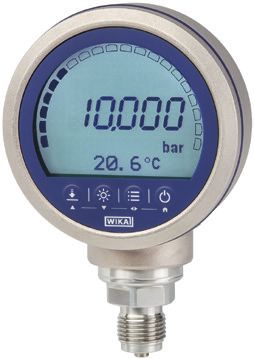
EN Operating instructions model GDI-100-D                            Page               3 - 42

DE Betriebsanleitung Typ GDI-100-D                                   Seite            43 - 83

   Further languages can be found at www.wika.com.

   © 07/2018 WIKA Alexander Wiegand SE & Co. KG
   All rights reserved. / Alle Rechte vorbehalten.
   WIKA® is a registered trademark in various countries.
   WIKA® ist eine geschützte Marke in verschiedenen Ländern.
                                                                                                  14269994.01 07/2018 EN/DE

   Prior to starting any work, read the operating instructions!
   Keep for later use!

   Vor Beginn aller Arbeiten Betriebsanleitung lesen!
   Zum späteren Gebrauch aufbewahren!

    2                                              WIKA operating instructions, model GDI-100-D
Contents

                            Contents
                            1. General information                                                                                         5
                            2. Short overview                                                                                              6
                               2.1 Overview  .   .   .   .   .   .   .   .   .   .   .   .   .   .   .   .   .   .   .   .   .   .   .   . 6
                               2.2 Description . . . . . . . . . . . . . . . . . . . . . . . 6                                                 EN
                               2.3 Scope of delivery  .  .  .  .  .  .  .  .  .  .  .  .  .  .  .  .  .  .  .  .  . 6
                               2.4 Technical passport  .  .  .  .  .  .  .  .  .  .  .  .  .  .  .  .  .  .  .  .  . 7
                            3. Safety                                                                                                      8
                               3.1 Explanation of symbols  .  .  .  .  .  .  .  .  .  .  .  .  .  .  .  .  .  .  . 8
                               3.2 Intended use  .  .  .  .  .  .  .  .  .  .  .  .  .  .  .  .  .  .  .  .  .  .  . 8
                               3.3 Improper use  .   .   .   .   .   .   .   .   .   .   .   .   .   .   .   .   .   .   .   .   .   .  9
                               3.4 Personnel qualification  .   .   .   .   .   .   .   .   .   .   .   .   .   .   .   .   .   .   .  9
                               3.5 Personal protective equipment  .   .   .   .   .   .   .   .   .   .   .   .   .   .   .   .  10
                               3.6 Handling of insulating gases and gas mixtures  .  .  .  .  .  .  .  .  .  . 10
                               3.7 Valid standards and guidelines  .   .   .   .   .   .   .   .   .   .   .   .   .   .   .   .  11
                               3.8 Labelling, safety marks  .  .  .  .  .  .  .  .  .  .  .  .  .  .  .  .  .  . 12
                            4. Design and function                                                                                       13
                               4.1 Front foil  .  .  .  .  .  .  .  .  .  .  .  .  .  .  .  .  .  .  .  .  .  .  . 13
                               4.2 Integrated data logger  .   .   .   .   .   .   .   .   .   .   .   .   .   .   .   .   .   .   .  16
                               4.3 Voltage supply  .  .  .  .  .  .  .  .  .  .  .  .  .  .  .  .  .  .  .  .  . 16
                               4.4 WIKA-Wireless  .   .   .   .   .   .   .   .   .   .   .   .   .   .   .   .   .   .   .   .   . 16
                               4.5 Protective rubber cap for case  .  .  .  .  .  .  .  .  .  .  .  .  .  .  .  . 16
                            5. Transport, packaging and storage                                                                          17
                               5.1 Transport  .   .   .   .   .   .   .   .   .   .   .   .   .   .   .   .   .   .   .   .   .   .   . 17
                               5.2 Packaging and storage  .  .  .  .  .  .  .  .  .  .  .  .  .  .  .  .  .  . 17
                            6. Commissioning, operation                                                                                  18
                               6.1 Mechanical mounting  .  .  .  .  .  .  .  .  .  .  .  .  .  .  .  .  .  .  . 18
                               6.2 Normal operation  .  .  .  .  .  .  .  .  .  .  .  .  .  .  .  .  .  .  .  . 19
                               6.3 Menu functions  .   .   .   .   .   .   .   .   .   .   .   .   .   .   .   .   .   .   .   .   . 19
                                 6.3.1 Pressure units  .  .  .  .  .  .  .  .  .  .  .  .  .  .  .  .  .  .  .  . 23
                                 6.3.2 Automatic power-off  .  .  .  .  .  .  .  .  .  .  .  .  .  .  .  .  .  . 23
                                 6.3.3 Battery voltage display  .  .  .  .  .  .  .  .  .  .  .  .  .  .  .  .  . 24
                                 6.3.4 Current temperature display   .   .   .   .   .   .   .   .   .   .   .   .   .   .   . 24
                                 6.3.5 Setting the damping  .  .  .  .  .  .  .  .  .  .  .  .  .  .  .  .  .  . 24
14269994.01 07/2018 EN/DE

                                 6.3.6 Configuring the sampling rate  .   .   .   .   .   .   .   .   .   .   .   .   .   .   .  24
                                 6.3.7 TARE (Tare setting, not available for SF₆ units)  .   .   .   .   .   .   .   .   .  24
                                 6.3.8 Function locking   .   .   .   .   .   .   .   .   .   .   .   .   .   .   .   .   .   .   . 25
                               6.4 Communication with WIKA-Cal calibration software  .   .   .   .   .   .   .   .   .  25
                                 6.4.1 Activating WIKA-Wireless in the GDI-100-D  .  .  .  .  .  .  .  .  .  . 25
                                 6.4.2 App “myWIKA device”  .  .  .  .  .  .  .  .  .  .  .  .  .  .  .  .  . 26
                             WIKA operating instructions, model GDI-100-D                                                                 3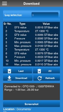
Contents

     7. Faults                                                                                                     32
     8. Maintenance, cleaning and recalibration                                                                    33
         8.1 Maintenance  .  .  .  .  .  .  .  .  .  .  .  .  .  .  .  .  .  .  .  .  .  . 33
         8.2 Battery replacement  .  .  .  .  .  .  .  .  .  .  .  .  .  .  .  .  .  .  . 34
         8.3 Cleaning  .  .  .  .  .  .  .  .  .  .  .  .  .  .  .  .  .  .  .  .  .  .  . 35
         8.4 Recalibration  .   .   .   .   .   .   .   .   .   .   .   .   .   .   .   .   .   .   .   .   .   .  35
EN   9. Dismounting, return and disposal                                                                           36
         9.1 Dismounting  .  .  .  .  .  .  .  .  .  .  .  .  .  .  .  .  .  .  .  .  .  . 36
         9.2 Return  .   .   .   .   .   .   .   .   .   .   .   .   .   .   .   .   .   .   .   .   .   .   .   . 37
         9.3 Disposal  .  .  .  .  .  .  .  .  .  .  .  .  .  .  .  .  .  .  .  .  .  .  . 37
     10. Specifications                                                                                            38
     11. Accessories                                                                                               42

     Declarations of conformity can be found online at www.wika.com.

                                                                                                                        14269994.01 07/2018 EN/DE

      4                                                        WIKA operating instructions, model GDI-100-D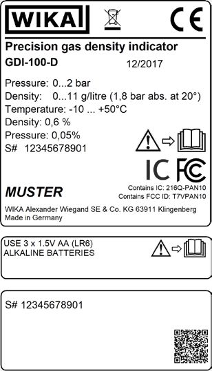
1. General information

                            1. General information
                            ■■ The precision gas density indicator described in the operating instructions has been
                              manufactured using state-of-the-art technology. All components are subject to strin-
                              gent quality and environmental criteria during production. Our management systems
                              are certified to ISO 9001 and ISO 14001.
                                                                                                                          EN
                            ■■ These operating instructions contain important information on handling the instrument.
                              Working safely requires that all safety instructions and work instructions are observed.

                            ■■ Observe the relevant local accident prevention regulations and general safety regulati-
                              ons for the instrument's range of use.

                            ■■ The operating instructions are part of the product and must be kept in the immediate
                              vicinity of the instrument and readily accessible to skilled personnel at any time. Pass
                              the operating instructions on to the next operator or owner of the instrument.

                            ■■ Skilled personnel must have carefully read and understood the operating instructions
                              prior to beginning any work.

                            ■■ The general terms and conditions contained in the sales documentation shall apply.

                            ■■ Subject to technical modifications.

                            ■■ Factory calibrations / DKD/DAkkS calibrations are carried out in accordance with
                              international standards.

                            ■■ Further information:
                               - Internet address:            www.wika.de / www.wika.com
                               - Relevant data sheet:         SP 60.07
                               - Application consultant:      Tel.: +49 9372 132-0
                                                              Fax: +49 9372 132-406
                                                              info@wika.de

                            Abbreviations, definitions
                            “XXX”        Menu XXX will be selected
14269994.01 07/2018 EN/DE

                            [XXX]        Press XXX button

                             WIKA operating instructions, model GDI-100-D                                             5
2. Short overview
2. Short overview
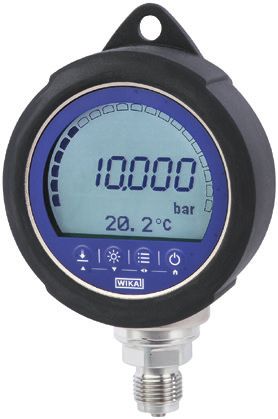
2.1 Overview
1 Display
2 Process connection
EN
2.2 Description
The model GDI-100-D precision gas density indicator combines the high accuracy of
digital technology with the convenience and easy handling of an analogue gas density
indicator. It is suitable for any SF₆ application that requires monitoring and data storage of
the status parameters of density, pressure and temperature.
Many user-configurable functions have been implemented in the GDI-100-D (e.g. logging,
sampling rate, automatic power-off and Min-Max measurement). The GDI-100-D, along-
side SF₆ applications, can be used as a calibration instrument or in any application requi-
ring high-accuracy pressure measurement. With the uncompensated pressure measure-
ment, additional functions are available (e.g. Tare, damping).
2.3 Scope of delivery
■■ Precision gas density indicator model GDI-100-D
■■ Operating instructions
■■ 3.1 calibration certificate per DIN EN 10204
■■ 3 x 1.5 V AA alkaline batteries
14269994.01 07/2018 EN/DE
Cross-check scope of delivery with delivery note.
Manufacturer-dependent colour shades of the metal case do not lead to any
quality impairment.
6 WIKA operating instructions, model GDI-100-D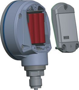
2. Short overview

                            2.4 Technical passport
                            The technical passport can be retrieved from the product page or directly from the corres-
                            ponding web application.

                                                                                                                              EN

                                                  Web application                   Product page

                            WIKA - Intelligent serial number
                            The WIKA intelligent serial number and the corresponding web application is the central
                            tool in which all the required information on the specific instrument can be found. After
                            entering the intelligent serial number into the web application, all instrument-specific
                            details on the manufactured version are displayed.

                            Under “Technical passport”, all the information such as measuring range, accuracy,
                            process connection, date of manufacture, etc., can be retrieved. You can also download
                            (calibration) certificates from this location.

                            Under “Article details”, further article details are listed, as well as documentation (e.g. the
                            data sheet and current operating instructions). From this view, the required information
                            can be printed directly via the [print view]. Via [e-mail], an e-mail is generated which alrea-
                            dy contains the intelligent serial number of the currently retrieved instrument and this can
                            be sent to any recipient (e.g. for re-ordering).
14269994.01 07/2018 EN/DE

                             WIKA operating instructions, model GDI-100-D                                               7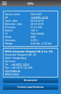
3. Safety

     3. Safety

     3.1    Explanation of symbols

                  WARNING!
                  ... indicates a potentially dangerous situation that can result in serious injury
                  or death, if not avoided.
EN

                  CAUTION!
                  ... indicates a potentially dangerous situation that can result in light injuries or
                  damage to property or the environment, if not avoided.

                  Information
                  ... points out useful tips, recommendations and information for efficient and
                  trouble-free operation.

     3.2 Intended use
     The GDI-100-D precision gas density indicator has been designed and built solely for the
     intended use described here, and may only be used accordingly.

     The precision gas density indicator is suitable for the following applications:
     ■■ Indication and data storage of gas density, pressure and temperature for SF₆
          gas-insulated equipment
     ■■ Calibration
     ■■ High-accuracy pressure measurement

     The precision gas density indicator has been developed for industrial use and must
     therefore only be used in commercial and industrial environments. The precision gas
     density indicator is suitable for indoor and outdoor use.

     Only use the measuring instrument in applications that lie within its technical performance
     limits (e.g. max. ambient temperature, pressure ranges, ...).
     → For performance limits see chapter 10 “Specifications”

     Refrain from unauthorised modifications to the instrument. Any use beyond or different to
                                                                                                         14269994.01 07/2018 EN/DE

     the intended use is considered as improper use.

     The technical specifications contained in these operating instructions must be observed.
     Improper handling or operation of the instrument outside of its technical specifications
     requires the instrument to be taken out of service immediately and inspected by an autho-
     rised WIKA service engineer.

      8                                                WIKA operating instructions, model GDI-100-D
3. Safety

                            Handle electronic precision measuring instruments with the required care (protect from
                            humidity, impacts, strong magnetic fields, static electricity and extreme temperatures, do
                            not insert any objects into the instrument or its openings).

                            The manufacturer shall not be liable for claims of any type based on operation contrary to
                            the intended use.
                                                                                                                          EN
                            3.3   Improper use

                                        WARNING!
                                        Injuries through improper use
                                        Improper use of the instrument can lead to hazardous situations and injuries.
                                        ▶▶ Refrain from unauthorised modifications to the instrument.
                                        ▶▶ Do not use the instrument with abrasive or viscous media.
                                        ▶▶ If the GDI-100-D is used in applications with oil as a pressure medium,
                                           make sure it will not be used with combustibles or gases directly after that
                                           because it can lead to dangerous explosions and danger to persons and
                                           machines.

                            Any use beyond or different to the intended use is considered as improper use.

                            3.4   Personnel qualification

                                        WARNING!
                                        Risk of injury should qualification be insufficient
                                        Improper handling can result in considerable injury and damage to equip-
                                        ment.
                                        ▶▶ The activities described in these operating instructions may only be
                                           carried out by skilled personnel who have the qualifications described
                                           below.

                            Skilled personnel
                            Skilled personnel, authorised by the operator, are understood to be personnel who,
                            based on their technical training, knowledge of measurement and control technology and
                            on their experience and knowledge of country-specific regulations, current standards and
                            directives, are capable of carrying out the work described and independently recognising
                            potential hazards.

                            Specifically when using SF₆ gas
14269994.01 07/2018 EN/DE

                            The plant operator must ensure that the handling of SF₆ gas is only carried out by a quali-
                            fied company or by qualified persons who have been specifically trained in accordance
                            with IEC 61634, section 4.3.1 or IEC 60480, section 10.3.1.

                             WIKA operating instructions, model GDI-100-D                                            9
3. Safety

     3.5 Personal protective equipment
     The personal protective equipment is designed to protect the skilled personnel from
     hazards that could impair their safety or health during work. When carrying out the various
     tasks on and with the instrument, the skilled personnel must wear personal protective
     equipment.

EN   Follow the instructions displayed in the work area regarding personal protective
     equipment!

     The requisite personal protective equipment must be provided by the operating company.

                  Wear safety goggles!
                  Safety goggles in accordance with EN 166, class 2. Protection of the eyes
                  from flying parts during coupling or releasing of the quick connections under
                  pressure.

                  Wear protective gloves!
                  Protect hands from friction, abrasion, cuts or deep injuries and also from
                  contact with hot surfaces.

     3.6 Handling of insulating gases and gas mixtures
     SF₆ gas is a greenhouse gas which is listed in the Kyoto Protocol. SF6 gas must not be
     released into the atmosphere, but must be collected in suitable containers.

     Properties of insulating gases
     ■■Colourless and odourless
     ■■Chemically neutral
     ■■Inert
     ■■Not flammable
     ■■Heavier than air
     ■■No toxicity
     ■■No damage to the ozone layer
     Detailed information is given in IEC 60376 and IEC 61634.

     Danger of suffocation caused by insulating gases and gas mixtures
     High concentrations of gases can lead to asphyxiation, since breathable air is displaced
     from the lungs with the inhalation of gas.
     Since SF₆ gas is heavier than air, it collects, especially, at ground level or lower-lying
                                                                                                   14269994.01 07/2018 EN/DE

     rooms below the reference level (e.g. cellars). This is particularly dangerous since SF6
     gas is colourless and odourless and thus may be imperceptable to people.

      10                                            WIKA operating instructions, model GDI-100-D
3. Safety
Danger caused by decomposition products
Insulating gas in electrical systems may contain decomposition products generated by
electric arcs:
■■ Gaseous sulphur fluorides
■■ Sulphur hexafluorides
■■ Solid and atomized metal fluorides, metal sulphides, metal oxides EN
■■ Hydrogen fluoride
■■ Sulphur dioxide
Decomposition products can be harmful to health.
■■ They can cause poisoning by inhalation, ingestion or contact with the skin.
■■ They may be irritating to the eyes, the respiratory system or the skin and burn them.
■■ Inhalation of large quantities may damage the lungs.
Observe the following safety instructions in order to avoid danger from insulating gas:
■■ Wear personal protective equipment.
■■ Read the material safety data sheet of the gas supplier.
■■ With large leaks, evacuate the area quickly.
■■ Ensure good ventilation.
■■ Ensure the leak tightness of the equipment with a leak detector (e.g. model GIR-10).
3.7 Valid standards and guidelines
Installation, assembly, commissioning:
■■ BGI 753 (SF₆ plants and equipment in Germany)
■■ IEC 61634 (Handling of SF₆ gas)
■■ IEC 60376 (New SF₆ gas, technical grade SF₆ gas)
■■ IEC 60480 (Used SF₆ gas)
■■ CIGRE report 276, 2005 (Practial SF₆ gas handling instructions)
Leaks during operation:
■■ IEC 60376 (New SF₆ gas, technical grade SF₆ gas)
■■ IEC 60480 (Used SF₆ gas)
■■ CIGRE 2002 (“SF₆ gas in the electrical industry”)
Repair work and maintenance:
■■ IEC 61634 (Use and handling of SF₆ gas in high-voltage switchgear and controlgear)
■■ CIGRE 1991 (Handling of SF₆ gas)
14269994.01 07/2018 EN/DE
■■ CIGRE report 276, 2005 (Practical SF₆ gas handling instructions)
■■ CIGRE report 163, 2000 (Guide for SF₆ gas mixtures)
Insulating gas is a colourless and odourless, chemically neutral, inert and
non-inflammable gas which is heavier than air, not toxic and not harmful to
the ozone layer. Detailed information is given in IEC 60376 and IEC 61634.
WIKA operating instructions, model GDI-100-D 113. Safety
3.8 Labelling, safety marks
Product label
The product label is located on the rear side.
EN
1
2
3
4
5
6
5
7
1 Product name 5 Serial number
2 Date of manufacture 6 Approvals
3 Measuring ranges 7 QR code
4 Accuracy specifications
Symbols
Before mounting and commissioning the instrument, ensure you read
the operating instructions!
14269994.01 07/2018 EN/DE
This marking on the instruments indicates that they must not be disposed of
in domestic waste. The disposal is carried out by return to the manufacturer
or by the corresponding municipal authorities.
12 WIKA operating instructions, model GDI-100-D4. Design and function
4. Design and function
4.1 Front foil
1
12
2
11 EN
3
4
10
5
9 6
8 7
Pos. Symbol The symbol lights up on:
1 ■■ Exceeding or dropping below the density range
■■ Exceeding or dropping below the pressure range
■■ Exceeding or dropping below the temperature range
■■ Logger memory is more than 90 % full
■■ Instrument error or battery status < 10 %
2 Log Logger function active
3 The battery symbol is lit continuously and is dependent upon the current battery
status.
Battery status 100 %
Outline and all segments are lit
Battery status 80 %
Outline and first three segments are lit
Battery status 60 %
Outline and first two segments are lit
14269994.01 07/2018 EN/DE
Battery status 40 %
Outline and first segment are lit
Battery status 20 %
Outline is lit continuously
⇒⇒ Insert new batteries (see chapter 8.2 „Batteriewechsel“).
WIKA operating instructions, model GDI-100-D 134. Design and function
Pos. Symbol The symbol lights up on:
4 Density and pressure indication
The 5 ½-digit 7-segment display always indicates the current value.
If the value is no longer current, lines will be displayed (in low-power
mode over 10 s)
Matrix field serves as menu and secondary display
EN 5
The matrix field consists of 4 x 21 cells (rows x columns) and serves
as a menu and secondary display.
10 Bar graph indicates the measured value
The bar graph consists of 20 segments and two end points at the
front and rear ends. The bar graph indicates the current measured
value proportionally to the measuring range. If the measuring range
has been underrun, the front point lights up; with an overrun, the rear
point lights up.
11 WIKA-Wireless
■■ Symbol is blinking: WIKA-Wireless is active but not connected
■■ Symbol is lit continuously: WIKA-Wireless is active and connected
12 Tare TARE function active
Note: This function is not available for SF₆ units.
14269994.01 07/2018 EN/DE
14 WIKA operating instructions, model GDI-100-D4. Design and function
Function buttons
The gas density indicator is controlled via 4 function buttons, with each button having a
main and a secondary function. In general, the information printed on the buttons corres-
ponds to the main function: “ZERO”, “LIGHT”, “MENU”, “ON/OFF”. Once the [MENU]
button is active, the secondary function applies. These are, from left to right: Cursor up
“UP / ▲”, cursor down “DOWN / ▼”, left/right cursor “L / ◀” or “R / ▶” and “HOME”.
EN
Pos. Button
6 On/Off button
The main function is switching the gas density indicator on and off.
If the gas density indicator is already in menu mode, a short press on the [On/
Off] button brings up “HOME”. A long press (at least 3 seconds) switches the
GDI-100-D off.
7 MENU button
Calling up the menu
By activating the [MENU] button, the menu mode is enabled. If the gas densi-
ty indicator is already in menu mode, depending on the display, “L” or “R”
will be executed. If the button is pressed for longer, after 2 seconds the cursor
switches (right ◀ or ▶ left).
Inputs are confirmed with the [MENU] button.
8 LIGHT button
Turning the backlighting on and off
By activating the [LIGHT] button (short or long press) the light is switched on.
The duration of the light being on depends on “LIGHT-OFF” in “SETTINGS”.
■■ 1 x pressing the [LIGHT] button (Light = On)
■■ 2 x pressing the [LIGHT] button (Light = Off)
If the GDI-100-D is in menu mode, with a short press on the [LIGHT] button,
the cursor can be moved downwards.
9 ZERO button
The current pressure value will be set to “0” (gauge) or reference pressure
(abs.).
By activating the [ZERO] button, the current pressure value is set to “0”. A
maximum of 5 % of the measuring span can be corrected.
If the GDI-100-D is in menu mode, with a short press on the [ZERO] button,
the cursor can be moved upwards.
14269994.01 07/2018 EN/DE
WIKA operating instructions, model GDI-100-D 154. Design and function
4.2 Integrated data logger
The gas density indicator features an integrated data logger.
This data logger can be turned on or off via [MENU] / [Logger] or via the "myWIKAde-
vice" app under [Logger] / [Upload].
4.3 Voltage supply
EN Three AA alkaline batteries are used as the voltage supply for the instrument. These are
included in delivery.
The battery life time is up to 2,000 hours for continuous operation (without backlighting
and with WIKA-Wireless deactivated).
In the upper right half of the display there is a symbol for the battery capacity. Instructions
on batteries (see chapter 8.2 „Batteriewechsel“).
The battery indicator lights up
To avoid false readings, replace the batteries.
Instructions on batteries (see chapter 8.2 „Batteriewechsel“).
4.4 WIKA-Wireless
To start wireless data transfer, you must set it to “On” under “Menu / Basic settings /
Wireless”. Once this has been done, the wireless symbol blinks in the display. As soon
as the gas density indicator is connected to a smartphone via this wireless interface, the
symbol lights continuously.
Under “Menu / Basic settings / Wireless / Wireless”, a distinction can be made
between the communication type WIKA-Wireless Classic or WIKA-Wireless Classic with
WIKA-Wireless Low Energy (= LE).
WIKA-Wireless Low Energy (= LE) is required to communicate with an IOS-enabled
mobile phone via the myWIKA-device smartphone app.
It is recommended to select WIKA-Wireless Classic for a connection with PC and/or an
Android-enabled instrument.
4.5 Protective rubber cap for case
Optionally, the gas density indicator can be fitted with an impact-resistant protective
rubber cap.
14269994.01 07/2018 EN/DE
16 WIKA operating instructions, model GDI-100-D5. Transport, packaging and storage
5. Transport, packaging and storage
5.1 Transport
Check gas density indicator for any damage that may have been caused by transport.
Obvious damage must be reported immediately.
CAUTION!
EN
Damage through improper transport
With improper transport, a high level of damage to property can occur.
▶▶ When unloading packed goods upon delivery as well as during internal
transport, proceed carefully and observe the symbols on the packaging.
▶▶ With internal transport, observe the instructions in chapter
5.2 „Verpackung und Lagerung“.
If the instrument is transported from a cold into a warm environment, the formation of
condensation may result in instrument malfunction. Before putting it back into operation,
wait for the instrument temperature and the room temperature to equalise.
5.2 Packaging and storage
Do not remove packaging until just before mounting.
Keep the packaging as it will provide optimum protection during transport (e.g. change in
installation site, sending for repair).
Permissible conditions at the place of storage:
■■ Storage temperature: -20 ... +70 °C (-4 ... +158 °F)
■■ Humidity: 0 ... 90 % relative humidity (no condensation)
Avoid exposure to the following factors:
■■ Direct sunlight or proximity to hot objects
■■ Mechanical vibration, mechanical shock (putting it down hard)
■■ Soot, vapour, dust and corrosive gases
Store the instrument in its original packaging in a location that fulfils the conditions listed
above. If the original packaging is not available, pack and store the instrument as descri-
bed below:
1. Remove the batteries from the instrument and store them separately, see chapter
8.2 „Batteriewechsel“.
2. Wrap the instrument in an antistatic plastic film.
3. Place the instrument, along with the shock-absorbent material, in the packaging.
4. If stored for a prolonged period of time (more than 30 days), place a bag containing a
14269994.01 07/2018 EN/DE
desiccant inside the packaging.
WIKA operating instructions, model GDI-100-D 176. Commissioning, operation
6. Commissioning, operation
Personnel: Skilled personnel
Tools: SW 27 open-ended spanner or torque spanner
Only use original parts (see chapter 11 „Zubehör“).
EN
WARNING!
Physical injuries and damage to property and the environment caused
by hazardous media
Upon contact with hazardous media (e.g. oxygen, acetylene, flammable or
toxic substances), harmful media (e.g. corrosive, toxic, carcinogenic, radioac-
tive), and also with refrigeration plants and compressors, there is a danger of
physical injuries and damage to property and the environment.
▶▶ Should a failure occur, aggressive media with extremely high temperature
and under high pressure or vacuum may be present at the instrument.
▶▶ For these media, in addition to all standard regulations, the appropriate
existing codes or regulations must also be followed.
6.1 Mechanical mounting
CAUTION!
Damage to the instrument
To avoid possible damage to gas density indicator or to test equipment,
follow the steps below:
▶▶ Make sure the threaded connections are clean and undamaged.
▶▶ The maximum permitted torque of the thread is 13.5 Nm = 10 ftlbs. This
permitted torque must NEVER be exceeded.
▶▶ The instrument should be installed in such a way that process-related
electrostatic charges (e.g. caused by flowing media) can be excluded.
▶▶ The case is rotatable by 330°. When turning do not touch the display.
▶▶ If the message “OL” is displayed, the measuring range has been excee-
ded and the pressure source must be removed immediately to prevent
damage to the internal sensor.
1. Seal the sealing faces.
2. At the mounting point, screw the gas density indicator in hand-tight.
▶▶ When screwing in, do not cross the threads.
14269994.01 07/2018 EN/DE
3. Tighten with a torque spanner using the spanner flats.
▶▶ The maximum torque is 13.5 Nm = 10 ftlbs.
18 WIKA operating instructions, model GDI-100-D6. Commissioning, operation
6.2 Normal operation
Make a long press on the [On/Off] button, in order to activate the precision digital gas
density indicator. Push the button again to turn it off.
After switching on, the start-up screen with pressure range and firmware version is shown
on the display for approx. 3 seconds.
Zeroing the display: Press and hold the [ZERO] button. EN
The gas density indicator must be set to 0 with the [ZERO] button before each use.
6.3 Menu functions
▶▶ Press [MENU] button to start
Press the buttons (▶) to enter the individual menu level.
Select the parameters and the menu level using the buttons (▼ or ▲).
Menu level 1 Menu level 2 Menu level 3
Measuring mode
Unit
g/l
kg/m³
SF6bar abs.
SF6Mpa abs.
SF6kPa abs.
SF6psi abs.
SF6bar rel., default
SF6MPa rel.
SF6kPa rel.
SF6psi rel.
bar
mbar
psi
kg/cm²
Pa
kPa
hPa
MPa
mmH2O
mH2O
inH2O
14269994.01 07/2018 EN/DE
inH2O (4 °C)
inH2O (60 °F)
inH2O (20 °C)
ftH2O
mmHg
cmHg
WIKA operating instructions, model GDI-100-D 196. Commissioning, operation
Menu level 1 Menu level 2 Menu level 3
inHg
inHg (0 °C)
inHg (60 °F)
kp/cm²
lbf/ft²
EN kN/m²
atm
Torr
micron
m
cm
mm
feet
inch
UserUnit 1
UserUnit 2
UserUnit 3
Peak values (not available for SF₆ units)
Off (default)
On
reset
Temperature
Off (default)
°C
°F
K
Tare (not available for SF₆ units)
Off (default)
On
Offset (0.0000)
[Limit: ±9.9999 {depending on resolution}]
Mean value
Off (default)
On
Interval (10 s) [limit: 300 s]
Rate
14269994.01 07/2018 EN/DE
Off (default)
/s
/min
Resolution
4
5 (default)
5-1/2
20 WIKA operating instructions, model GDI-100-D6. Commissioning, operation
Menu level 1 Menu level 2 Menu level 3
Damping (not available for SF₆ units)
Off (default)
low
medium
high
Measuring rate EN
For SF₆ units:
1/s
3/s (default)
For pressure:
1/s
3/s
10/s
50/s [max. speed]
Logger interval
Alarm (not available for SF₆ units)
Off (default)
On
lower (1.0000)
[Limit: ±measuring range limit – 10 %]
upper (10.000)
[Limit: ±measuring range limit + 10 %]
Level (not available for SF₆ units)
Density 1.0 [kg/dm³]
kg/dm³ (default)
lb/ft³
kg/m³
Logger
Start / Stop
Start / Stop
Interval
10.0 s (default)
[Limit: 0 … 3,600 s]
0 corresponds to the logging with measuring
rate.
Duration
Off
14269994.01 07/2018 EN/DE
On
Duration (0000 h 00 min 01 s)
[Limit: 9999 h 59 min 59 s]
WIKA operating instructions, model GDI-100-D 216. Commissioning, operation
Menu level 1 Menu level 2 Menu level 3
Start time
Off
On
Start time (00 h 00 min)
[Limit: 23 h 59 min]
EN Clear last
No (default)
Yes
Clear all
No (default)
Yes
Default
Wireless
Off
On (default)
Language
English (default)
German
Spanish
French
Italian
Switch-off time
Off
5 min
15 min (default)
30 min
Light off
Off (=light is permanently on)
10 s (default)
30 s
60 s
120 s
Contrast
20 %
30 %
40 %
14269994.01 07/2018 EN/DE
50 % (default)
60 %
70 %
80 %
22 WIKA operating instructions, model GDI-100-D6. Commissioning, operation
Menu level 1 Menu level 2 Menu level 3
Time
hh : mm : ss [AM / PM]
Time format
24 h (default)
12 h [AM / PM]
Date EN
DD / MM /YYYY
Date format
dd.mm.yyyy (default)
dd/mm/yyyy
mm/dd/yyyy
yyyy-mm-dd
Factory reset
No (default)
Yes
Info
S# (e.g.: 1A00023458) = serial number
T# (e.g.: ABCDEFG12345) = tag number
MR: (e.g.: 0 ... 16 bar) = measuring range
ManufDat. (e.g.: 10/05/2018) = date of manufacture
CalibDat. (e.g.: 10/05/2018) = calibration date
Firmware
Memory status In %
Op hrs [d h]
O. pressure [bar]
O. temp [ °C]
6.3.1 Pressure units
The GDI-100-D is factory preset to the SF6 temperature-compensated unit of SF6bar
abs..
6.3.2 Automatic power-off
The time duration for automatic power-off can be selected from four predefined and fixed
steps. Thus it can be set to “5 min”, “15 min”, “30 min” or “Off”. With “Off”, the instrument
remains activated until it is switched off using the [ON/OFF] button or until the batteries
are empty. If a time has been set, then the GDI runs from the last button press for this time
14269994.01 07/2018 EN/DE
and then switches itself off automatically. Also, during a wireless transmission or through
a log, the time is stopped and restarted after completion of this.
WIKA operating instructions, model GDI-100-D 236. Commissioning, operation
6.3.3 Battery voltage display
The current battery voltage as well as the remaining useful life of the battery are displayed
via the battery symbol.
6.3.4 Current temperature display
The gas density indicator is temperature-compensated for SF6 gas. This option displays
EN the temperature measured by the internal sensor. The value indication can be switched
from degrees of Fahrenheit to degrees of Celsius.
6.3.5 Setting the damping
With the “Damping” setting, one can select between three different, fixed, preconfigured
filter settings. With “Off”, the filter is inactive and not in operation. Thus only the display
on the gas density indicator is damped. The pressure value that is read over the wireless
transmission or the value written to the logger will not be damped.
6.3.6 Configuring the sampling rate
The sampling rate defines how frequently the density or the pressure is measured.
Options for SF₆ gas are 1 and 3 measurements per second or the logger interval.
Standard pressure values can be recorded with 1, 3, 10 and 50 measurements per
second. The shortest response time for SF₆ gas is 3 measurements per second and for
standard pressure values, 50 measurements per second. The display rate is set perma-
nently at 3 x display refresh/s.
6.3.7 TARE (Tare setting, not available for SF₆ units)
With this option, a constant offset value can be set. If, for example, TARE is set to 10 bar
and the measured pressure is 13 bar, the measured value will be displayed as 3 bar.
A pressure of 7 bar would then be displayed as -3 bar. The TARE value is set manually
using the ▲ and ▼ buttons and depends on the technical units of measurement and the
resolution selected for the display. The TARE value can be set to the maximum scale
range.
The bar graph always indicates the actual pressure with respect to the entire
measuring range, irrespective of the tare setting. This is performed for safety reasons so
that in case of “0” indication it can still be displayed that the corresponding pressure is
present at the pressure gauge.
Contrary to the operating principle of the ZERO button, the offset value under tare does
not contribute to the shift of the characteristic curve. If you change the unit, the configured
offset value will be automatically converted to match the new unit.
14269994.01 07/2018 EN/DE
24 WIKA operating instructions, model GDI-100-D6. Commissioning, operation
6.3.8 Function locking
Access to adjustable parameters can be selectively turned off, once set, to prevent
unauthorized changes to configuration.
Locking the Zero button
The operator can no longer make a “ZERO” using the keypad - it is still possible over the
wireless transmission. EN
Locking the Menu button
Access to the “Menu” is locked. If “ZERO” is not locked, this can still be executed. Over
the wireless transmission, all settings can still be read or written.
Instrument write protection (not available for SF₆ units)
When this lock is set, via the menu on the local display menu as well as over the wireless
transmission, access to the settings is read-only - thus no alteration of the settings is
possible.
If the “ZERO” lock is not set, the “ZERO” function is still possible.
The individual locks can only be set via WIKA-Cal calibration software over the wireless
transmission. For this, the input of a 4-digit PIN is required. This is set to “0000” on supply
and can be changed.
6.4 Communication with WIKA-Cal calibration software
As soon as a connection exists over WIKA-Wireless, it can communicate with the
WIKA-Cal calibration software. It can transmit and evaluate live measurements or also
measurements that have already been made, without difficulty.
6.4.1 Activating WIKA-Wireless in the GDI-100-D
1. Press the Menu button.
2. Press and hold the ▶ or ◀ button until the “Wireless” default setting appears in the
matrix field.
3. Switch on wireless by pressing the ▼ or ▲ button.
4. Confirm the setting by pressing the Menu button.
⇒⇒Once wireless has been switched on, the WIKA-Wireless symbol blinks in the
display
⇒⇒The WIKA-Wireless symbol is lit continuously when a connection has been
created.
14269994.01 07/2018 EN/DE
WIKA operating instructions, model GDI-100-D 256. Commissioning, operation
6.4.2 App “myWIKA device”
Via the “myWIKA device” app and the WIKA-Wireless connection,
the GDI-100-D can be conveniently configured for logging tasks
through a smartphone. During the SF₆ density and pressure measu-
rement, the value is displayed in the required unit directly on the
EN smartphone.
Moreover, further parameters like the current temperature can be
checked. It is also possible to retrieve more detailed instrument infor-
mation directly from the WIKA website. In addition, the app allows
control and saving of log procedures.
Logs that have been saved on the mobile phone can be transferred
to a PC and be read and processed as required.
For iOS-based mobile phones, the app is For mobile phones with an Android
available in the Apple Store under below operating system, the app is available in
link. the Play Store under below link.
Download here Download here
14269994.01 07/2018 EN/DE
26 WIKA operating instructions, model GDI-100-D6. Commissioning, operation
6.4.2.1 Establishing a wireless connection with the GDI-100-D
Activate the “Bluetooth Scan”, set the “Device Filter” to “All” and establish a wireless
connection to the GDI-100-D with a click. In the event that the GDI-100-D does not
appear directly in the list of available instruments, the centre of the screen must be
clicked and the finger moved downwards. This updates the currently opened window, and
the available instruments can be selected. This capability for updating is available
throughout the entire app. After the connection has been successfully established, the EN
info screen will be displayed. All relevant information of the instrument, such as serial
number, date of manufacture, battery status, accuracy and measuring range are listed
here.
14269994.01 07/2018 EN/DE
WIKA operating instructions, model GDI-100-D 276. Commissioning, operation
6.4.2.2 Displaying the current measured value
By clicking on “Measure”, the current measured value can be displayed directly on the
smartphone. The green bar is scaled to match the measurand currently applied. If
temperature measurement is activated, a temperature value is also output. Screenshots
can easily be saved and sent by clicking on Screenshot.
EN
14269994.01 07/2018 EN/DE
28 WIKA operating instructions, model GDI-100-D6. Commissioning, operation
6.4.2.3 Configuring data logger and starting measurement
The GDI-100-D can be configured for logging tasks either directly on the instrument or via
the “myWIKA Device” app. For this, click on the “Upload” button in the category “Logger”
and set the desired parameters.
■■ Interval: C
alculates a mean value over the duration of the set interval. If 0 is entered,
the measured values are stored in the instrument with the set sampling rate. EN
■■ Duration: Defines the duration of the measurement.
■■ Start time: Defines the start time of the measurement.
■■ Upload: The settings are transmitted to the GDI-100-D.
■■ Start now: Starts measurement immediately.
■■ Stop: Stops measurement immediately.
■■ Preview: Enables preliminary viewing of the measured value.
14269994.01 07/2018 EN/DE
WIKA operating instructions, model GDI-100-D 296. Commissioning, operation
6.4.2.4 Display and send recorded values from the data logger
By clicking on “Download”, stored logs with the corresponding measured values can be
viewed directly on and exported to the smartphone.
■■ Under “Log Selection” the logs stored on the instrument can be selected.
■■ With “Last” and “All”, either the last or all logs stored on the instrument can be deleted.
■■ With “Download” the selected logs can be exported (e.g. by e-mail). After each deletion
EN
procedure, the view must be updated with “Refresh”.
■■ Exported data can be further analysed on a computer, in order to, for example, identify
leaks early, calculate leak rates or to carry out condition-based maintenance at the gas
tank.
14269994.01 07/2018 EN/DE
30 WIKA operating instructions, model GDI-100-D6.4.2.5 Changing the measuring units and measurement settings
Under “Device”, the instrument settings, such as measuring units and general settings,
can be changed.
EN
14269994.01 07/2018 EN/DE
WIKA operating instructions, model GDI-100-D 317. Faults
7. Faults
Personnel: The plant operator must ensure that the handling of SF₆ gas is only carried
out by a qualified company or by qualified persons who have been specifically trained in
accordance with IEC 61634, section 4.3.1 or IEC 60480, section 10.3.1.
Protective equipment: Protective gloves, safety goggles
EN Tools: SW 27 open-ended spanner or torque spanner
WARNING!
Physical injuries and damage to property and the environment caused
by hazardous media
Upon contact with hazardous media (e.g. oxygen, acetylene, flammable or
toxic substances), harmful media (e.g. corrosive, toxic, carcinogenic, radioac-
tive), and also with refrigeration plants and compressors, there is a danger of
physical injuries and damage to property and the environment.
Should a failure occur, aggressive media with extremely high temperature
and under high pressure or vacuum may be present at the instrument.
▶▶ For these media, in addition to all standard regulations, the appropriate
existing codes or regulations must also be followed.
▶▶ Use the requisite protective equipment.
CAUTION!
Physical injuries and damage to property and the environment
If faults cannot be eliminated by means of the listed measures, the
GDI-100-D must be taken out of operation immediately.
▶▶ Ensure that pressure or signal is no longer present and protect against
accidental commissioning.
▶▶ Contact the manufacturer.
▶▶ If a return is needed, please follow the instructions given in chapter 9.2
„Rücksendung“.
For contact details see chapter 1 „Allgemeines“ or the back page of the
operating instructions.
14269994.01 07/2018 EN/DE
32 WIKA operating instructions, model GDI-100-D7 Faults / 8. Maintenance, cleaning and recalibration
Display Causes Measures
Gas density / p The gas tank has a leak Carry out emissions detection
SF₆@20°C decreases with leak detector (e.g. GIR-10)
over time and remedy any leaks.
Low battery voltage, functioning is Insert new alkaline batteries, see
only guaranteed for a short period chapter 8.2 „Batteriewechsel“.
of time EN
OL Reading is significantly above or Check: Is the pressure within the
-OL below the measuring range = > permissible measuring range of
10 % FS the sensor?
No display or instru- Battery is empty Insert new alkaline batteries, see
ment is not respon- chapter 8.2 „Batteriewechsel“.
ding to button press
Batteries inserted incorrectly Ensure the correct polarity, see
chapter 8.2 „Batteriewechsel“.
System error Switch off the GDI-100-D, wait for
a short period of time, switch on
again
Defect in the GDI-100-D Send in for repair
8. Maintenance, cleaning and recalibration
Personnel: The plant operator must ensure that the handling of SF₆ gas is only carried
out by a qualified company or by qualified persons who have been specifically trained in
accordance with IEC 61634, section 4.3.1 or IEC 60480, section 10.3.1.
Special operating conditions require further appropriate knowledge, e.g. of aggressive
media.
Protective equipment: Protective gloves, safety goggles
Tools: SW 27 open-ended spanner or torque spanner
For contact details see chapter 1 „Allgemeines“ or the back page of the
operating instructions.
14269994.01 07/2018 EN/DE
8.1 Maintenance
The model GDI-100-D precision digital gas density indicator is maintenance-free.
Repairs must only be carried out by the manufacturer.
This does not apply to the replacement of alkaline batteries.
Only use original parts (see chapter 11 „Zubehör“).
WIKA operating instructions, model GDI-100-D 338. Maintenance, cleaning and recalibration
8.2 Battery replacement
Battery replacement
▶▶ Do not use rechargeable batteries!
▶▶ Always replace all three batteries together!
▶▶ The battery cover must be closed and locked in place!
▶▶ Secure the battery cover with the three screws!
EN ▶▶ Ensure the correct polarity.
Procedure
1. Turn off the instrument and lay it face down.
2. Loosen the three screws of the battery compartment, see Abb. 1 „Position des Batte-
riefachs“.
3. Remove the battery cover.
4. Insert the three AA-sized batteries in correct polarity. Only use permitted batteries, see
chapter 8.2 „Batteriewechsel“.
5. Put the battery cover on and screw it tight with the three screws.
⇒⇒Tighten the upper screw first.
Abb. 1 - Position of the battery compartment
If the instrument is not used for a long time, remove the batteries.
14269994.01 07/2018 EN/DE
34 WIKA operating instructions, model GDI-100-D8. Maintenance, cleaning and recalibration
8.3 Cleaning
CAUTION!
Physical injuries and damage to property and the environment
Improper cleaning may lead to physical injuries and damage to property and
the environment. Residual media at the dismounted instrument can result in a
risk to persons, the environment and equipment.
▶▶ Use the requisite protective equipment. EN
▶▶ Carry out the cleaning process as described below.
1. Prior to cleaning, isolate the instrument properly from the pressure source and switch
it off.
2. Use the requisite protective equipment.
3. Clean the instrument with a moist cloth. Electrical connections must not come into
contact with moisture!
CAUTION!
Damage to property
Improper cleaning may lead to damage to the instrument!
▶▶ Do not use any aggressive cleaning agents.
▶▶ Do not use any hard or pointed objects for cleaning.
▶▶ Do not use solvents or abrasives for cleaning.
4. Wash or clean the dismounted instrument, in order to protect persons and the environ-
ment from exposure to residual media.
8.4 Recalibration
We recommend that the instrument is regularly recalibrated by the manufacturer, with
time intervals of approx. 12 months. The basic settings will be corrected if necessary.
The calibration label is attached at the side of GDI-100-D. For instruments with protective
rubber cap, the calibration label is located beneath the protection cap.
Abb. 2 - GDI-100-D with protective Abb. 3 - GDI-100-D without protective
14269994.01 07/2018 EN/DE
rubber cap rubber cap
WIKA operating instructions, model GDI-100-D 359. Dismounting, return and disposal
9. Dismounting, return and disposal
Personnel: Skilled personnel
Protective equipment: Protective gloves, safety goggles
Tools: SW 27 open-ended spanner or torque spanner
WARNING!
EN
Physical injuries and damage to property and the environment
through residual media
Residual media and decomposition products at the dismounted model
GDI-100-D digital precision gas density indicator can result in a risk to
personnel, the environment and equipment.
▶▶ Observe the information in the material safety data sheet for the corres-
ponding medium.
▶▶ Use the requisite protective equipment.
▶▶ Wash or clean the dismounted instrument, in order to protect persons
and the environment from exposure to residual media or decomposition
products.
9.1 Dismounting
WARNING!
Physical injuries and damage to property and the environment
through residual media
Upon contact with hazardous media (e.g. SF₆ decomposition products,
oxygen, acetylene, flammable or toxic substances), harmful media (e.g.
corrosive, toxic, carcinogenic, radioactive), and also with refrigeration plants
and compressors, there is a danger of physical injuries and damage to
property and the environment.
▶▶ Wash or clean the dismounted instrument (following use), in order to
protect persons and the environment from exposure to residual media.
WARNING!
Physical injury
When dismounting, there is a danger from aggressive media, decomposition
products and high pressures.
▶▶ Dismount the measurement and test assembly when there is no pressure.
1. Switch off the GDI-100-D.
14269994.01 07/2018 EN/DE
2. Loosen the GDI-100-D with a spanner or torque spanner, using the spanner flats.
3. Screw out the GDI-100-D by hand.
4. If required, clean the GDI-100-D, see chapter 8.3 „Reinigung“.
36 WIKA operating instructions, model GDI-100-D9. Dismounting, return and disposal
9.2 Return
Strictly observe the following when shipping the instrument:
All instruments delivered to WIKA must be free from any kind of hazardous substances
(acids, bases, solutions, etc.) and must therefore be cleaned before being returned.
WARNING!
Physical injuries and damage to property and the environment EN
through residual media
Residual media at the dismounted instrument can result in a risk to persons,
the environment and equipment.
▶▶ With hazardous substances, attach the material safety data sheet for the
corresponding medium.
▶▶ Clean the instrument (see chapter 8.3 „Reinigung“).
When returning the instrument, use the original packaging or a suitable transport
packaging.
To avoid damage:
1. Wrap the instrument in an antistatic plastic film.
2. Place the instrument, along with the shock-absorbent material, in the packaging. Place
shock-absorbent material evenly on all sides of the transport packaging.
3. If possible, place a bag, containing a desiccant, inside the packaging.
4. Label the shipment as transport of a highly sensitive measuring instrument.
Information on returns can be found under the heading “Service” on our local
website.
9.3 Disposal
Incorrect disposal can put the environment at risk.
Dispose of instrument components and packaging materials in an environmentally
compatible way and in accordance with the country-specific waste disposal regulations.
This marking on the instruments indicates that they must not be disposed of
in domestic waste. The disposal is carried out by return to the manufacturer
or by the corresponding municipal authorities.
14269994.01 07/2018 EN/DE
WIKA operating instructions, model GDI-100-D 3710. Specifications
10. Specifications
Sensor technology
Measuring range see product label
Overload safety
EN Sensor 3 times
Indicator > 110 % FS or -10 % FS
Accuracy (density 0.6 % FS
measurement)
Accuracy (pressure 0.05 % FS
measurement)
Compensated -10 … +50 °C (14 ... 122 °F)
temperature range
Base instrument
Units
Density units SF₆ g/litre, kg/m³
Pressure units SF₆ at bar abs., psi abs., KPa abs., MPa abs.
20 °C bar rel., psi rel., KPa rel., MPa rel.
Pressure units Standard: psi, bar
Can be set to: mbar, kg/cm², Pa, hPa, kPa, Mpa, mmH₂O, mH₂O,
inH₂O, inH₂O (4 °C),
inH₂O (20 °C), inH₂O (60 °F), ftH₂O, mmHg, cmHg, inHg, inHg
(0 °C), inHg (60 °F), kp/cm², lbf/ft², kN/m², atm, Torr, micron, as well
as user-defined units
Indicator
Display 5 ½-digit 7-segment display (incl. a large matrix area for auxiliary
information)
Bar graph, 0 ... 100 %
Selectable backlighting
Rotatable case The case is rotatable by 330°.
Resolution 4 ... 5 ½ digits; adjustable; depending on the selected pressure unit
Functions
Communication Integrated Bluetooth interface, configuration, data transfer and
export with the WIKA “myWIKA device” app (available free-of-
14269994.01 07/2018 EN/DE
charge in Google Play Store and Apple App Store)
Measuring rate max. 3/s (density measurement)
max. 50/s (pressure measurement)
Menu languages English, German, Italian, French, Spanish, Russian and Polish
Memory Integrated data logger
38 WIKA operating instructions, model GDI-100-D10. Specifications
Base instrument
Menu functions ■■ Density measurement:
Power-off function, measuring rate, mean value filter, pressure
rate, mean value (via adjustable interval), indicator damping
■■ Pressure measurement:
Min./Max. alarm (visual), Power-off function, measuring rate,
mean value filter, pressure rate, mean value (via adjustable EN
interval), level indication, tare offset, indicator damping
Mean value interval 1 ... 300 seconds, adjustable
Data logger 2) Cyclic logger: Automatic recording of up to 1,000,000 values;
Cycle time: Selectable from 1 ... 3,600 s in steps of 1 second or by
measuring rate in the following steps:
Density measurement: 1/s, 3/s
Pressure measurement: 1/s, 3/s, 10/s and 50/s
Material
Wetted parts Stainless steel 316L
Case Aluminium die-casting, nickel-plated
Voltage supply
Power supply 3 x 1.5 V AA alkaline batteries
Battery life Typically 2,000 ... 2,500 h (without backlighting and WIKA-Wireless
not active)
Battery status display Symbol display with 4 bars indicates the battery status in 25 %
steps.
Permissible ambient
conditions
Operating temperature -10 ... +50 °C (14 ... 122 °F)
Medium temperature -10 ... +50 °C (14 ... 122 °F)
Storage temperature -20 ... +70 °C (-4 ... +158 °F)
Relative humidity < 95 % r. h. (non-condensing)
Case
Dimensions approx. 100 x 150 x 59 mm (3.9 x 5.9 x 2.3 in)
Process connection G½B
Ingress protection IP65
Weight Standard: incl. batteries approx. 680 g (1.5 lbs)
with protective rubber cap: approx. 820 g (1.81 lbs)
14269994.01 07/2018 EN/DE
1) The user-defined units can only be set via the “My WIKA Device” software. The GDI-100-D must be fitted with WIKA-Wireless.
2) To use the logger function, “My WIKA device” software is needed. The logger data can be downloaded as CSV file.
WIKA operating instructions, model GDI-100-D 3910. Specifications
WIKA-Wireless 1)
Frequency range 2,400 ... 2,500 MHz
HF output power max. 2 dBm (+ 2 dBi)
Number of channels
Classic 79
EN Low Energy 40
Channel spacing
Classic 1 MHz
Low Energy 2 MHz
Bandwidth 1 or 2 MHz
Output power 4 dBm / 10 mW
Maximum output power under fault conditions for Ex ia: 490
mW
Process connection G½B
1) Requires Bluetooth® 2.1 (PC or smartphone)
Approvals
Logo Description Country
EU declaration of conformity European Union
■■ RoHS directive
■■ R&TTE directive
EN 300 328 harmonised frequency range 2,400 … 2,500 MHz
is used; Bluetooth® Classic, max. transmission power 10 mW.
The instrument may be used without limitations in the EU and
also CH, NO and LI.
Certificates
Certificate
Calibration 1) 3.1 calibration certificate per EN 10204
Recommended 1 year (dependent on conditions of use)
recalibration interval
14269994.01 07/2018 EN/DE
1) Calibrated in vertical mounting position with process connection facing downwards
Approvals and certificates, see website
40 WIKA operating instructions, model GDI-100-D10. Specifications
Dimensions in mm (in)
Without protective rubber cap
Ø 100,7 (3,96) 58,9 (2,32)
EN
114,9 (4,53)
110,1 (4,33)
27
32,5 (1,28
35,5 (1,40)
20 (0,79)
3 (0,12)
G 1/2 34,7 (1,37)
Ø 36 (1,42)
Ø 44,4 (1,75)
With protective rubber cap
Ø 108,4 (4,27) 66,4 (2,61)
5 (0,20)
(0,39)
Ø 10
116 (4,57)
120,8 (4,75)
172,4 (6,79)
27
14269994.01 07/2018 EN/DE
35,5 (1,40)
32,5 (1,28
20 (0,79)
3 (0,12)
G 1/2 36,8 (1,45)
Ø 36 (1,42)
Ø 44,4 (1,75)
WIKA operating instructions, model GDI-100-D 4111. Accessories
11. Accessories
Protective rubber cap
(Order number: 14209565)
Ø 108,4 (4,27) 66,4 (2,61)
EN
5 (0,20)
(0,39)
Ø 10
116 (4,57)
120,8 (4,75)
172,4 (6,79)
27
35,5 (1,40)
32,5 (1,28
20 (0,79)
3 (0,12)
G 1/2 36,8 (1,45)
Ø 36 (1,42)
Ø 44,4 (1,75)
14269994.01 07/2018 EN/DE
42 WIKA operating instructions, model GDI-100-DInhalt
Inhalt
1. Allgemeines 45
2. Kurzübersicht 46
2.1 Überblick . . . . . . . . . . . . . . . . . . . . . . . 46
DE
2.2 Beschreibung . . . . . . . . . . . . . . . . . . . . . . 46
2.3 Lieferumfang . . . . . . . . . . . . . . . . . . . . . . 46
2.4 Gerätepass . . . . . . . . . . . . . . . . . . . . . . 47
3. Sicherheit 48
3.1 Symbolerklärung . . . . . . . . . . . . . . . . . . . . . 48
3.2 Bestimmungsgemäße Verwendung . . . . . . . . . . . . . . 48
3.3 Fehlgebrauch . . . . . . . . . . . . . . . . . . . . . . 49
3.4 Personalqualifikation . . . . . . . . . . . . . . . . . . . 50
3.5 Persönliche Schutzausrüstung . . . . . . . . . . . . . . . . 50
3.6 Umgang mit Isoliergasen und Gasgemischen . . . . . . . . . . . 51
3.7 Geltende Normen und Richtlinien . . . . . . . . . . . . . . . 52
3.8 Beschilderung, Sicherheitskennzeichnungen . . . . . . . . . . . 53
4. Aufbau und Funktion 54
4.1 Frontfolie . . . . . . . . . . . . . . . . . . . . . . . 54
4.2 Integrierter Datenlogger . . . . . . . . . . . . . . . . . . 57
4.3 Spannungsversorgung . . . . . . . . . . . . . . . . . . . 57
4.4 WIKA-Wireless . . . . . . . . . . . . . . . . . . . . . 57
4.5 Gummischutzkappe für Gehäuse . . . . . . . . . . . . . . . 57
5. Transport, Verpackung und Lagerung 58
5.1 Transport . . . . . . . . . . . . . . . . . . . . . . . 58
5.2 Verpackung und Lagerung . . . . . . . . . . . . . . . . . 58
6. Inbetriebnahme, Betrieb 59
6.1 Mechanische Montage . . . . . . . . . . . . . . . . . . 59
6.2 Normalbetrieb . . . . . . . . . . . . . . . . . . . . . 60
6.3 Menüfunktionen . . . . . . . . . . . . . . . . . . . . . 60
6.3.1 Druckeinheiten . . . . . . . . . . . . . . . . . . . . 64
6.3.2 Automatische Abschaltung . . . . . . . . . . . . . . . . 64
6.3.3 Batteriespannung anzeigen . . . . . . . . . . . . . . . 65
6.3.4 Anzeige der aktuellen Temperatur . . . . . . . . . . . . . 65
14269994.01 07/2018 EN/DE
6.3.5 Dämpfung einstellen . . . . . . . . . . . . . . . . . . 65
6.3.6 Abtastrate konfigurieren . . . . . . . . . . . . . . . . . 65
6.3.7 TARE (Tara einstellen, nicht für SF₆-Einheiten verfügbar) . . . . . 65
6.3.8 Funktionssperre . . . . . . . . . . . . . . . . . . . 66
6.4 Kommunikation mit der Kalibriersoftware WIKA-Cal . . . . . . . . . 66
6.4.1 WIKA-Wireless im GDI-100-D aktivieren . . . . . . . . . . . 66
WIKA Betriebsanleitung, Typ GDI-100-D 43Inhalt
6.4.2 App „myWIKA device” . . . . . . . . . . . . . . . . . 67
7. Störungen 73
8. Wartung, Reinigung und Rekalibrierung 74
8.1 Wartung . . . . . . . . . . . . . . . . . . . . . . . . 74
8.2 Batteriewechsel . . . . . . . . . . . . . . . . . . . . . 75
8.3 Reinigung . . . . . . . . . . . . . . . . . . . . . . . 75
DE 8.4 Rekalibrierung . . . . . . . . . . . . . . . . . . . . . 76
9. Demontage, Rücksendung und Entsorgung 77
9.1 Demontage . . . . . . . . . . . . . . . . . . . . . . 77
9.2 Rücksendung . . . . . . . . . . . . . . . . . . . . . . 78
9.3 Entsorgung . . . . . . . . . . . . . . . . . . . . . . 78
10. Technische Daten 79
11. Zubehör 83
Konformitätserklärungen finden Sie online unter www.wika.de.
14269994.01 07/2018 EN/DE
44 WIKA Betriebsanleitung, Typ GDI-100-DYou can also read