Hand-held thermometer, model CTH6200 Hand-Held-Thermometer, Typ CTH6200 - Hand-held thermometer model CTH6200 with temperature probe Pt100 - Mensor
←
→
Page content transcription
If your browser does not render page correctly, please read the page content below
Operating instructions
Betriebsanleitung
Hand-held thermometer, model CTH6200 EN
Hand-Held-Thermometer, Typ CTH6200 DE
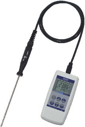
Hand-held thermometer model CTH6200 with temperature probe Pt100
EN Operating instructions model CTH6200                                 Page           3 - 46

DE Betriebsanleitung Typ CTH6200                                        Seite        47 - 90

   Further languages can be found at www.wika.com.

   © 07/2021 WIKA Alexander Wiegand SE & Co. KG
   All rights reserved. / Alle Rechte vorbehalten.
   WIKA® is a registered trademark in various countries.
   WIKA® ist eine geschützte Marke in verschiedenen Ländern.

   Prior to starting any work, read the operating instructions!
   Keep for later use!

   Vor Beginn aller Arbeiten Betriebsanleitung lesen!
   Zum späteren Gebrauch aufbewahren!
                                                                                                 2146872.02 07/2021 EN/DE

    2                                               WIKA operating instructions, model CTH6200
Contents
Contents
1. General information 5
2. Short overview 6
2.1 Overview . . . . . . . . . . . . . . . . . . . . . . . . 6
2.2 Description . . . . . . . . . . . . . . . . . . . . . . . 6
2.3 Scope of delivery . . . . . . . . . . . . . . . . . . . . . 6 EN
3. Safety 7
3.1 Explanation of symbols . . . . . . . . . . . . . . . . . . . 7
3.2 Intended use . . . . . . . . . . . . . . . . . . . . . . . 7
3.3 Improper use . . . . . . . . . . . . . . . . . . . . . . . 8
3.4 Personnel qualification . . . . . . . . . . . . . . . . . . . 8
3.5 Labelling, safety marks . . . . . . . . . . . . . . . . . . . 9
3.5.1 Product label . . . . . . . . . . . . . . . . . . . . . . . . . . . . . . . . . . .9
3.5.2 Explanation of symbols . . . . . . . . . . . . . . . . . . . . . . . . . . . . . 9
4. Design and function 10
4.1 Display . . . . . . . . . . . . . . . . . . . . . . . . 10
4.2 Function buttons and operation . . . . . . . . . . . . . . . . 11
4.3 Electrical connections . . . . . . . . . . . . . . . . . . . 12
4.4 Voltage supply . . . . . . . . . . . . . . . . . . . . . . 13
4.4.1 Battery operation . . . . . . . . . . . . . . . . . . . . . . . . . . . . . . . . 13
4.4.2 Using the optional power supply unit . . . . . . . . . . . . . . . . . . . . . 14
4.5 Serial interface . . . . . . . . . . . . . . . . . . . . . 15
4.6 Temperature probe . . . . . . . . . . . . . . . . . . . . 15
4.6.1 Available temperature probes . . . . . . . . . . . . . . . . . . . . . . . . . 16
4.6.2 Connecting/replacing the temperature probe . . . . . . . . . . . . . . . . 16
4.6.3 General information on temperature probes . . . . . . . . . . . . . . . . . 17
5. Transport, packaging and storage 18
5.1 Transport . . . . . . . . . . . . . . . . . . . . . . . 18
5.2 Packaging and storage . . . . . . . . . . . . . . . . . . . 18
6. Commissioning, operation 19
6.1 Commissioning . . . . . . . . . . . . . . . . . . . . . 19
6.2 Menu navigation of the main menu . . . . . . . . . . . . . . . 20
6.3 Configuring the instrument . . . . . . . . . . . . . . . . . 22
2146872.02 07/2021 EN/DE
6.3.1 Temperature unit (Unit) . . . . . . . . . . . . . . . . . . . . . . . . . . . . 22
6.3.2 Display resolution (rES) . . . . . . . . . . . . . . . . . . . . . . . . . . . . 22
6.3.3 Compensation characteristic (Lin E.751) . . . . . . . . . . . . . . . . . . 23
6.3.4 Zero point correction/offset (OFfS) . . . . . . . . . . . . . . . . . . . . . . 23
6.3.5 Slope correction (SCaL) . . . . . . . . . . . . . . . . . . . . . . . . . . . . 24
WIKA operating instructions, model CTH6200 3Contents
6.3.6 Power-off delay (P.oFF) . . . . . . . . . . . . . . . . . . . . . . . . . . . . 24
6.3.7 Instrument output (Ovt) . . . . . . . . . . . . . . . . . . . . . . . . . . . . 24
6.3.8 Interface address (adr.) . . . . . . . . . . . . . . . . . . . . . . . . . . . . 24
6.3.9 Analogue output scaling with dAC.0 and dAC.1 (dAC.) . . . . . . . . . . . . 25
6.3.10 Alarm (AL.) . . . . . . . . . . . . . . . . . . . . . . . . . . . . . . . . . . . 26
6.3.11 Real-time clock (CLOC) . . . . . . . . . . . . . . . . . . . . . . . . . . . . . 26
6.4 Operation of the logger function . . . . . . . . . . . . . . . . 27
EN 6.4.1 Manual recording (Func-Stor) . . . . . . . . . . . . . . . . . . . . . . . . 28
6.4.2 Automatic recording with adjustable cycle time (Func-CYCL) . . . . . . . . 29
7. Faults 31
8. Maintenance, cleaning and recalibration 33
8.1 Maintenance . . . . . . . . . . . . . . . . . . . . . . 33
8.2 Battery replacement . . . . . . . . . . . . . . . . . . . . 33
8.3 Cleaning . . . . . . . . . . . . . . . . . . . . . . . . 34
8.4 Recalibration . . . . . . . . . . . . . . . . . . . . . . 34
9. Dismounting, return and disposal 35
9.1 Dismounting . . . . . . . . . . . . . . . . . . . . . . 35
9.2 Return . . . . . . . . . . . . . . . . . . . . . . . . 36
9.3 Disposal . . . . . . . . . . . . . . . . . . . . . . . . 36
10. Specifications 37
10.1 Digital indicator model CTH6200 . . . . . . . . . . . . . . . 37
10.2 Temperature probe model CTP62x0 . . . . . . . . . . . . . . 39
10.3 Genauigkeitsangaben der Messkette . . . . . . . . . . . . . 40
10.4 Certificates . . . . . . . . . . . . . . . . . . . . . . 41
10.5 Dimensions in mm [in] . . . . . . . . . . . . . . . . . . . 42
10.5.1 Digital indicator CTH6200 . . . . . . . . . . . . . . . . . . . . . . . . . . . 42
10.5.2 Temperature probe model CTP62x0 . . . . . . . . . . . . . . . . . . . . . 43
10.5.3 Electrical connections . . . . . . . . . . . . . . . . . . . . . . . . . . . . . 44
11. Accessories 45
Declarations of conformity can be found online at www.wika.com.
2146872.02 07/2021 EN/DE
4 WIKA operating instructions, model CTH62001. General information
1. General information
■ The hand-held thermometer model CTH6200 described in the operating instructions
have been designed and manufactured using state-of-the-art technology. All
components are subject to stringent quality and environmental criteria during
production. Our management systems are certified to ISO 9001 and ISO 14001.
■ These operating instructions contain important information on handling the instrument.
Working safely requires that all safety instructions and work instructions are observed. EN
■ Observe the relevant local accident prevention regulations and general safety
regulations for the instrument's range of use.
■ The operating instructions are part of the product and must be kept in the immediate
vicinity of the instrument and readily accessible to skilled personnel at any time. Pass
the operating instructions on to the next operator or owner of the instrument.
■ Skilled personnel must have carefully read and understood the operating instructions
prior to beginning any work.
■ The general terms and conditions contained in the sales documentation shall apply.
■ Subject to technical modifications.
■ Factory calibrations / DKD/DAkkS calibrations are carried out in accordance with
international standards.
■ Further information:
- Internet address: www.wika.de / www.wika.com
- Relevant data sheet: CT 51.01
- Application consultant: Tel.: +49 9372 132-0
Fax: +49 9372 132-406
info@wika.de
■ Version key for firmware
Firmware version Validity
V 1.8 07/2008 to 11/2009
V 1.9 12/2009 to 07/2019
V 2.2 Since 07/2019
2146872.02 07/2021 EN/DE
WIKA operating instructions, model CTH6200 52. Short overview
2. Short overview
2.1 Overview
1 Sensor connection cable
2 Hand-held thermometer model
CTH6200
EN 3 Temperature probe model CTP62x0
3
1
2
2.2 Description
The CTH6200 hand-held thermometer can be used as a calibration instrument and also
for any application which requires accurate temperature measurement.
An immersion and a penetration probe are available as reference temperature probes for
the hand-held thermometer with a measuring range of -50 ... +250 °C [-58 ... +482 °F].
For measuring the temperature, you can select between °C and °F.
An integrated data logger and various other functions (such as Min., Max., hold, tare, zero
point correction, alarm, power-off, variable measuring rate etc.) ensure that the hand-held
thermometer can be used for many different applications.
2.3 Scope of delivery
■ Hand-held thermometer model CTH6200
■ 9 V battery
■ 3.1 calibration certificate per DIN EN 10204
2146872.02 07/2021 EN/DE
■ Choice of temperature probes
Cross-check scope of delivery with delivery note.
6 WIKA operating instructions, model CTH62003. Safety
3. Safety
3.1 Explanation of symbols
WARNING!
... indicates a potentially dangerous situation that can result in serious injury
or death, if not avoided.
EN
CAUTION!
... indicates a potentially dangerous situation that can result in light injuries or
damage to property or the environment, if not avoided.
DANGER!
... identifies hazards caused by electrical power. Should the safety
instructions not be observed, there is a risk of serious or fatal injury.
WARNING!
... indicates a potentially dangerous situation that can result in burns, caused
by hot surfaces or liquids, if not avoided.
Information
... points out useful tips, recommendations and information for efficient and
trouble-free operation.
3.2 Intended use
The model CTH6200 hand-held thermometer is suitable for all precise temperature
measurement tasks from -50 ... +250 °C [-58 ... +482 °F].
This instrument is not permitted to be used in hazardous areas!
The instrument has been designed and built solely for the intended use described here,
and may only be used accordingly.
The technical specifications contained in these operating instructions must be observed.
Improper handling or operation of the instrument outside of its technical specifications
requires the instrument to be taken out of service immediately and inspected by an
2146872.02 07/2021 EN/DE
authorised WIKA service engineer.
Handle electronic precision measuring instruments with the required care (protect from
humidity, impacts, strong magnetic fields, static electricity and extreme temperatures,
do not insert any objects into the instrument or its openings). Connectors and female
connectors must be protected from contamination.
WIKA operating instructions, model CTH6200 73. Safety
The manufacturer shall not be liable for claims of any type based on operation contrary to
the intended use.
3.3 Improper use
WARNING!
Injuries through improper use
EN Improper use of the instrument can lead to hazardous situations and injuries.
▶ Refrain from unauthorised modifications to the instrument.
▶ Do not use the instrument within hazardous areas.
▶ Do not use the instrument with abrasive or viscous media.
▶ Observe the operating parameters in accordance with chapter
10 “Specifications”.
Any use beyond or different to the intended use is considered as improper use.
3.4 Personnel qualification
WARNING!
Risk of injury should qualification be insufficient
Improper handling can result in considerable injury and damage to property.
▶ The activities described in these operating instructions may only be
carried out by skilled personnel who have the qualifications described
below.
Skilled personnel
Skilled personnel, authorised by the operator, are understood to be personnel who,
based on their technical training, knowledge of measurement and control technology and
on their experience and knowledge of country-specific regulations, current standards and
directives, are capable of carrying out the work described and independently recognising
potential hazards.
Special operating conditions require further appropriate knowledge, e.g. of aggressive
media.
2146872.02 07/2021 EN/DE
8 WIKA operating instructions, model CTH62003. Safety
3.5 Labelling, safety marks
3.5.1 Product label
The operator is obliged to maintain the product label in a legible condition.
Product label for hand-held thermometer (example)
The product label is fixed on the rear of the hand-held.
Kalibriertechnik / Calibration Technology
EN
1
4 2
3
1 Product name
2 Article number
3 Date of manufacture (month-year)
4 Serial number
3.5.2 Explanation of symbols
Before mounting and commissioning the hand-held thermometer,
ensure you read the operating instructions!
Do not dispose of with household waste. Ensure a proper disposal in
accordance with national regulations.
2146872.02 07/2021 EN/DE
WIKA operating instructions, model CTH6200 94. Design and function
4. Design and function
4.1 Display
1
2
EN
3
4
5
8
6
7
1 Offset
Zero point correction is activated
2 Corr
Slope correction is activated
3 Main display
Current temperature display
4 Symbol
Indicates a low battery and other warnings
5 Secondary display
Display of Min, Max. or hold value
6 Logg
Arrow appears, logger function was selected via menu
Arrow blinking: Automatic recording (Logg CYCL) active
7 AL
Arrow appears when there is an alarm
Arrow blinking: Alarm is active
2146872.02 07/2021 EN/DE
8 MIN / MAX / HLD
Indicates whether Min., Max. or hold value is shown in secondary display
10 WIKA operating instructions, model CTH62004. Design and function
4.2 Function buttons and operation
1 2 3
EN
6 5 4
Pos. Symbol Meaning
1 On/Off button
ON Switching the CTH6200 on and off
OFF
Display of the respective Max. memory value
2 ▲ ■ Press briefly
MAX By pressing the [▲/MAX] button, the maximum value measured will be
displayed. Pressing it again hides it.
■ Press for > 2 seconds
To delete the Max. value
3 Activate the tare function, zero point correction
▲
■ Tare function
TARA
Function only within the configuration menu for selection of the menu
parameters
4 Activate hold function or logger function
STORE
(See chapter 6.4 “Operation of the logger function”)
QUIT ■ Confirmation of the entry, return to measurement (in menu)
■ Hold function (press briefly)
By pressing the [STORE/QUIT] button, the last measured value will be
shown in the lower display. Pressing it again hides the value again (only if
logger is deactivated).
2146872.02 07/2021 EN/DE
■ Logger function
Activated by the [STORE/QUIT] button, only if the logger function has been
activated (see chapter 6.4 “Operation of the logger function”).
WIKA operating instructions, model CTH6200 114. Design and function
Pos. Symbol Meaning
5 Display of the respective Min. memory value
MIN
▲ ■ Press briefly
By pressing the [MIN/▼] button, the minimum value measured will be
displayed. Pressing it again hides it.
■ Press for > 2 seconds
To delete the Min. value
EN 6 SET
Enter configuration
By pressing the [SET/MENU] button for approx. 2 seconds, the settings
MENU
such as configuration, adjustment, alarm logger and system clock can be
accessed.
Abbreviations, definitions
“XXX” Menu XXX is accessed
[XXX] Press button XXX
‘XXX’ Menu ‘XXX’ will be displayed
4.3 Electrical connections
On the upper edge of the instrument are located the connection socket CH1 for the
connection of model CPT62x0 temperature probe (see chapter 4.6 “Temperature probe”)
and the socket for the connection of the WIKA interface cable (see chapter 4.5 “Serial
interface”).
The female connectors for the connection of the interface can also be used for the
function of analogue output. For this, a corresponding analogue connection cable must
be used.
The “interface” or “analogue output” operating mode must be configured via
menu and affects battery life!
Top view
Interface connector or optional
1
analogue output
Connection for temperature probe
2146872.02 07/2021 EN/DE
2
2 1
12 WIKA operating instructions, model CTH62004. Design and function
Side view (left)
Connection of power supply unit for voltage
3
supply
EN
3
4.4 Voltage supply
The voltage supply of the instrument is made via a 9 V battery. It is included in delivery.
Alternatively, a 9 V rechargeable battery can be used which can be charged using a
charging unit for 9 V rechargeable batteries.
The battery life is approx. 300 hours of continuous operation with one sensor and a
measuring rate of 2/s.
Alternatively, an additional power supply unit can be used for a permanent power supply.
4.4.1 Battery operation
The battery indicator lights up
To avoid false readings, replace the batteries.
If 'bAt' is displayed in the lower display, the battery has been run down
2146872.02 07/2021 EN/DE
and must be replaced or the rechargeable battery is empty and must be
charged with a suitable charging unit. However, the instrument function is
still ensured for a certain time.
WIKA operating instructions, model CTH6200 134. Design and function
If 'bAt' is displayed in the upper display, the battery has been completely
run down or the rechargeable battery is empty.
If the instrument is not used for a long time, the battery/rechargeable battery
should be removed.
EN The real-time clock has to be set again once the battery has been
reconnected.
The battery and rechargeable battery must only be used in a proper fashion
and must be disposed of properly in line with the current, national regulations.
When storing the instrument at over 50 °C [122 °F], the battery/rechargeable
battery must be taken out.
4.4.2 Using the optional power supply unit
DANGER!
Danger to life caused by electric current
Upon contact with live parts, there is a direct danger to life.
▶ Only use the original power supply unit from WIKA, which is available as
accessory.
▶ If there is any visible damage to the case or the wiring, do not use the
power supply unit!
▶ Never install nor store the power supply unit in the following locations, as
this can lead to a failure in operation:
■ Places where there is strong humidity or condensation
■ Outdoors
▶ Disconnect the power supply unit from the mains supply when it won't be
used for a longer period of time.
▶ The power supply unit is maintenance-free. It must not be opened (danger
of electrical shock).
▶ Before cleaning, disconnect the power supply unit from the mains supply.
Do not clean with chemical cleaning agents. Only clean with a dry cloth.
The power supply unit enables a permanent power supply for the CTH6200
without using a 9 V battery or a 9 V rechargeable battery.
The power supply unit is not suitable for recharging the 9 V rechargeable
2146872.02 07/2021 EN/DE
battery. The charging of the 9 V rechargeable battery must only be made
using an external charging unit.
14 WIKA operating instructions, model CTH62004. Design and function
4.5 Serial interface
For the data transfer to a computer, only use the interface cable from WIKA. These are
suitable for connection to a USB interface (USB driver needed) or an RS-232 interface.
USB interface cable
The USB interface cable consists of a USB connector (model A) at one end of the cable
and a 3.5 mm stereo jack connector at the other end of the cable.
The cable is approx. 2 m [6.6 ft] long.
EN
RS-232 interface cable
The RS-232 interface cable consists of a 9-pin Sub-D female connector at one end of the
cable and a 3.5 mm stereo jack connector at the other end of the cable.
The cable is approx. 1.5 m [4.9 ft] long.
Interface converter
With an galvanically isolated interface converter, the instrument can be connected to
an RS-232 interface of a PC (USB adapter possible on request) in order to visualise the
data with the WIKA data logger evaluation software GSoft. The transmission is protected
against transmission errors by extensive safety mechanisms (CRC).
4.6 Temperature probe
CAUTION!
Damage to the instrument
If third-party temperature probes are used, they can damage the hand-held
thermometer and the temperature probe.
▶ Only use model CTP62x0 temperature probes!
The CTH6200 is designed for connection of a Pt100 4-wire probe and should be done as
follows:
4-wire connection
4-wire connection
Pt100
2146872.02 07/2021 EN/DE
View of the pins of the probe connector
WIKA operating instructions, model CTH6200 154. Design and function
2- or 3-wire connection
It is also possible to connect a 2- or 3-wire probe to the CTH6200. However, it should be
noted that measured errors occur due to cable and contact resistances, but these can be
compensated for by the zero point correction.
3-wire connection 2-wire connection
EN
Pt100 Pt100
View of the pins of the probe connector
4-pin mini DIN connector
It is also possible to fit a 4-pin mini-DIN connector with interlocking for self-assembly.
4.6.1 Available temperature probes
The hand-held has been designed so that all sensors of the CTH series can be
connected without the need for any readjustment, see chapter 10 “Specifications”.
4.6.2 Connecting/replacing the temperature probe
WARNING!
Risk of burns!
The temperature probes can be extremely hot or cold.
▶ Let the temperature probe cool down sufficiently before replacing it!
Before switching the instrument on, connect the temperature probe,
otherwise it may not be correctly identified by the instrument.
1. Switch off the instrument to connect or change the temperature probe.
2. Connect the hand-held thermometer and the temperature probe. To do this, connect
2146872.02 07/2021 EN/DE
the 4-pin mini-DIN connector on the hand-held to CH1 in accordance with the
orientation guide.
▶ Connect the connector without tilting the threads.
⇒ If the connector is positioned correctly, it can be plugged in without any significant
effort.
16 WIKA operating instructions, model CTH62004. Design and function
▶ To disconnect the temperature probe, do not pull on the cable, but rather only on the
connector sleeve.
4.6.3 General information on temperature probes
Heat dissipation through probe construction
Especially for measurements of temperatures that deviate extremely from the ambient
temperature, measurement uncertainties occur if the heat dissipation through the probe EN
is not taken into account. For this reason, measurements in liquids should be immersed
sufficiently deep and then stirred. When measuring gases, the probe tube should
protrude as far as possible into the gas to be measured (e.g. for duct measurements) and
the gas should flow around the probe as strongly as possible.
Permissible probe temperature range
Pt100 sensors are suitable for very wide temperature ranges. The permissible
temperature limits of the probe used must be observed. Exceeding the permissible range
usually provides an inaccurate measuring result, or the probe may even be permanently
damaged!
When measuring high temperatures, the probe tube length should be long enough that
the temperature at the handle remains low.
Self-heating
The measuring current used is only 0.3 mA. This means that in practice the sensor
heating of even very small sensor elements is negligible.
Evaporative cooling
When measuring the air temperature, the probe should be dry, otherwise the temperature
measured will be too low (cooling through evaporation).
2146872.02 07/2021 EN/DE
WIKA operating instructions, model CTH6200 175. Transport, packaging and storage
5. Transport, packaging and storage
5.1 Transport
Check hand-held thermometer and temperature probe for any damage that may have
been caused by transport.
Obvious damage must be reported immediately.
CAUTION!
EN Damage through improper transport
With improper transport, a high level of damage to property can occur.
▶ When unloading packed goods upon delivery as well as during internal
transport, proceed carefully and observe the symbols on the packaging.
▶ With internal transport, observe the instructions in chapter 5.2 “Packaging
and storage”.
If the instrument is transported from a cold into a warm environment, the formation of
condensation may result in instrument malfunction. Before putting it back into operation,
wait for the instrument temperature and the room temperature to equalise.
5.2 Packaging and storage
Do not remove packaging until just before mounting.
Keep the packaging as it will provide optimum protection during transport (e.g. change in
use, sending for repair).
Permissible conditions at the place of storage:
■ Storage temperature: -25 ... +70 °C [-13 ... +158 °F]
■ Humidity: 0 ... 95 % relative humidity (non-condensing)
Avoid exposure to the following factors:
■ Direct sunlight or proximity to hot objects
■ Mechanical vibration, mechanical shock (putting it down hard)
■ Soot, vapour, dust and corrosive gases
Store the instrument in its original packaging in a location that fulfils the conditions
listed above. If the original packaging is not available, pack and store the instrument as
described below:
1. Wrap the instrument in an antistatic plastic film.
2. Place the instrument, along with the shock-absorbent material, in the packaging.
2146872.02 07/2021 EN/DE
3. If stored for a prolonged period of time (more than 30 days), place a bag containing a
desiccant inside the packaging.
18 WIKA operating instructions, model CTH62006. Commissioning, operation
6. Commissioning, operation
Personnel: Skilled personnel
WARNING!
Physical injuries and damage to property and the environment caused
by hazardous media
Upon contact with hazardous media (e.g. oxygen, acetylene, flammable
or toxic substances), harmful media (e.g. corrosive, toxic, carcinogenic,
EN
radioactive), and also with refrigeration plants and compressors, there is a
danger of physical injuries and damage to property and the environment.
Should a failure occur, aggressive media with extremely high temperature
may be present at the instrument.
▶ For these media, in addition to all standard regulations, the appropriate
existing codes or regulations must also be followed.
6.1 Commissioning
Before switching the instrument on, connect the temperature probe,
otherwise it may not be correctly identified by the instrument, see chapter
4.6.2 “Connecting/replacing the temperature probe”.
1. Connect the temperature probe to the female connector provided on the hand-held.
⇒ It must be possible to insert the connector into the female connector without much
effort.
⇒ The connection socket is located at the top of the instrument case. Next to these
are located the serial or analogue interfaces.
2. Ensure that a full 9 V battery or a full 9 V rechargeable battery is inserted.
3. Switch on the CTH6200 with the [ON/OFF] button.
Following the segment test, the instrument displays the following short information about
its configuration:
■ The type of characteristic curve
■ The time
■ If a slope correction has been carried out, the display will indicate this by showing
'SCAL' + value
■ If a zero point correction has been carried out, the display will indicate this by showing
'OFFS' + value.
2146872.02 07/2021 EN/DE
After changing the battery the menu for setting the clock ‘CLOC’ is displayed
automatically.
Check the clock and adjust if necessary (see chapter 6.3.11 “Real-time clock (CLOC)”).
The instrument is then ready for measurement.
WIKA operating instructions, model CTH6200 196. Commissioning, operation
6.2 Menu navigation of the main menu
Menu tree
EN SET
MENU (Press for 2 seconds)
Stored data 1)
STORE Read
Recall of the stored individual value logger data, see
▲
QUIT TARA
Lo66 chapter 6.4 “Operation of the logger function”
SET
MENU
STORE Set Configuration
▲
QUIT TARA Unit 2) / Resolution 2) / Characteristic curve 2) / Zero
Conf point and slope correction 2) / Mean value filter 2) /
SET Power-off / Interface / Base address
MENU
STORE Set Alarm
▲
QUIT
AL TARA
Min./Max. alarm visual with/without buzzer
SET
MENU
Set Logger 2)
STORE
Switch from hold to logger function:
▲
QUIT TARA
Lo66 Individual values (SToR) or cyclic (CYCL)
SET
MENU
STORE Set System clock
▲
QUIT
CLOC TARA
Time / Year / Day and month
SET
MENU
▲ MIN STORE
▲
▲
MAX TARA QUIT
(ring - shift) Set parameter Next parameter Store or quit
2146872.02 07/2021 EN/DE
1) Appears only if data has been stored in the individual value logger memory
2) Appears only if no data has been stored in the logger, see chapter 6.4 “Operation of the logger function”
20 WIKA operating instructions, model CTH62006. Commissioning, operation
Menu Para- Values Meaning
meter
[MENU] ▶ ▲ or ▼
read Read Logg: Read manual individual value logger
Lo66 (Only if data are available, see chapter 6.4 “Operation of the logger function”)
SEt Set Configuration: General settings
ConF Unit °C All temperatures in degree Celsius 1)
°F All temperatures in degree Fahrenheit 1) EN
rES 0.1 Resolution 0.1 °C 1)
0.01 Resolution 0.01 °C 1)
Auto Resolution is selected automatically 1)
Lin E.751 Characteristic curve per EN 60751 1)
USEr User characteristic curve (default: EN 60751 1)
Changeable via GSoft evaluation software)
OFFS -2.50 ... 2.50 °C The zero point of the measurement will be displaced by this
or value to compensate for deviations of the probe and the
-4.50 ... 4.50 °F measuring instrument. 1)
oFF Zero point correction is deactivated (= 0.0 °C) 1)
SCAL -2.000 ... 2.000 The measuring slope will be changed by this factor [in
%] to compensate deviations of probe and measuring
instrument. 1)
oFF Slope correction factor deactivated (= 0.000) 1)
t.au6 1 ... 30 Mean value filter, duration in seconds 1)
oFF Mean value filter is deactivated 1)
P.oFF 1 ... 120 Auto power-off delay in minutes.
If no button is pressed and there is no data transfer via the
interface, the instrument will switch itself off automatically
after this interval.
oFF Auto power-off function deactivated (continuous operation)
Ovt oFF No output function, lowest current consumption
SEr Instrument output is serial interface
dAC Instrument output is analogue output
Adr. 01, 11 ... 91 Base address of the instrument for interface communication
(only if serial interface is selected)
dAC.0 -200 ... +850 °C / Zero point setting for Out = dAC: Temperature at which the
-328 ... +1,562 °F analogue output should output 0 V (only for Out = dAC)
dAC.1 -200 ... +850 °C / Slope setting for Out = dAC: Temperature at which the
-328 ... +1,562 °F analogue output should output 1 V (only for Out = dAC)
Set Alarm: Alarm function configuration 2)
2146872.02 07/2021 EN/DE
SEt
AL. AL. on Alarm sensor is on; is indicated acoustically
no.So Alarm sensor is on; is not indicated acoustically
oFF No alarm function
AL.Lo -200 °C ... AL.Hi Min. alarm limit (not if AL.oFF)
AL.Hi AL.Lo ... +850 °C Max. alarm limit (not if AL.oFF)
WIKA operating instructions, model CTH6200 216. Commissioning, operation
Menu Para- Values Meaning
meter
[MENU] ▶ ▲ or ▼
SEt Set Logger: Logger function configuration 1)
Lo66 Func CYCL Cyclic: Logger function “cyclic logger”
Stor Store: Logger function “individual value logger”
oFF No logger function
EN CYCL 0:01 ... 60:00 Cycle time for cyclic logger [minutes:seconds]
SEt Set clock: Setting of real-time clock
CLOC CLOC HH:MM Setting the time hours:minutes
YEAr YYYY Setting the year
dAtE TT.MM Setting the date day.month
1) If there is data in the logger memory, these menu items cannot be accessed. If these should be changed, the data must first be
deleted (see chapter 6.4 “Operation of the logger function”).
2) If an alarm function limit is crossed (over or under), this is signalled by a “hooting” and a beeping.
If the [SET/MENU] and [STORE/QUIT] buttons are pressed together for
longer than 2 seconds, the factory settings will be restored.
6.3 Configuring the instrument
To change settings, press the [SET/MENU] button. All important parameters for the
measurements are changed here.
Settings are made as follows:
1. Press the [SET/MENU] button for 2 seconds.
⇒ The main menu “SEt” is accessed.
2. Keep pressing the [SET/MENU] button until the desired function is displayed.
3. With the [▶/TARA] button, select the parameters.
4. With the [MIN/▼] or [▲/MAX] buttons, set the parameters.
5. With the [STORE/QUIT] button, confirm the entry.
6. Press the [SET/MENU] button.
⇒ Return to main menu.
6.3.1 Temperature unit (Unit)
The measured temperature can be displayed either in °C or in °F.
2146872.02 07/2021 EN/DE
6.3.2 Display resolution (rES)
The default setting is 'Auto', i.e. the instrument automatically switches to the most
favourable resolution. Either 0.1 °C/°F or 0.01 °C/°F, depending on the current
temperature to be measured.
22 WIKA operating instructions, model CTH62006. Commissioning, operation
For measurements of temperatures that are close to the switching limits, it may be more
convenient to maintain a certain resolution, e.g. to facilitate logging.
In this case, select the appropriate resolution.
6.3.3 Compensation characteristic (Lin E.751)
This function uses the standard conversion resistance to temperature in accordance with
EN 60751 (Lin E.751). Other linearisations can also be used.
User characteristic curve can be read out and written back with GSoft evaluation EN
software.
The characteristic curve consists of a table (resistance [Ohm] / temperature [°C]) with a
total of 50 value pairs.
The characteristic curve in accordance with EN 60751 uses the temperature
scale ITS90 and the following calculation formula:
Temperatures < 0 °C:
Rneg(T) = 100 [1 + 3.908310-3 * T - 5.77510-7 * T2 - 4.18310-12 * (T - 100) * T3]
Temperatures ≥ 0 °C:
Rpos(T): = 100 (1 + 3.908310-3 * T - 5.77510-7 * T2)
Please note!
Temperature measurements with a user characteristic curve may only be
carried out in the temperature range for which the user characteristic curve
was determined. Measurements with a user characteristic curve outside the
calibrated range can lead to large measuring deviations. For measurements
outside the checked range, the characteristic curve must therefore be set in
accordance with DIN EN 60751 (Lin E.751).
6.3.4 Zero point correction/offset (OFfS)
The zero point correction, together with the slope correction, is mainly used for the
adjustment of probe deviations.
For temperature measurement, a zero point correction can be made:
2146872.02 07/2021 EN/DE
Displayed temperature = measured temperature - offset
WIKA operating instructions, model CTH6200 236. Commissioning, operation
Default setting
'off' = 0.0°, i.e. no correction is made. If a value other than 'off' is set, this is indicated by
the offset arrow in the display during operation.
Standard characteristic curve (Lin E.751) and user characteristic curve (Lin USEr) have
separate correction settings.
6.3.5 Slope correction (SCaL)
EN The slope correction, together with the zero point correction, is mainly used for the
adjustment of probe deviations.
The slope of the measurement can be influenced by this factor (factor is in %):
Displayed value [°C] = measured value [°C] * (1+Scal/100)
or
Displayed value [°F] = (measured value [°F] - 32 °F) * (1+Scal/100) + 32 °F
Default setting
'off' = 0.000, i.e. no correction is made. If a value other than 'off' is set, this is indicated
by the Corr arrow in the display during operation.
Standard characteristic curve (Lin E.751) and user characteristic curve (Lin USEr) have
separate correction settings.
6.3.6 Power-off delay (P.oFF)
If no button is pressed and no serial communication occurs during the power-off delay,
the instrument will automatically switch itself off. The power-off delay can be set between
1 and 120 min. If “P.oFF = oFF” then the power-off function is deactivated.
6.3.7 Instrument output (Ovt)
The output can be used as a USB or RS-232 interface or as an analogue output (0 ... 1 V).
If the output is not needed, we recommend switching it off, as this reduces the current
consumption of the instrument.
6.3.8 Interface address (adr.)
With a galvanically isolated interface converter (accessories on request), the instrument
2146872.02 07/2021 EN/DE
can be connected directly to a USB or RS-232 interface of a PC. It can connect up to 5
measuring instruments simultaneously. This requires that all instruments have a different
base address (the base addresses must be configured accordingly).
Setting the base address of the instrument for interface communication.
The assignment of the base address can be between 01, and 11 ... 91.
24 WIKA operating instructions, model CTH62006. Commissioning, operation
The transmission is protected against transmission errors by extensive safety
mechanisms (CRC).
Our GSoft data logger evaluation software is available for this purpose.
GSoft data logger evaluation software
The GSoft data logger evaluation software is used to display the logger data from the
model CTH6200 hand-held thermometer on a PC in tabular form and as a chart.
■ Easy operation with self-explanatory toolbars
■ Data from the pressure and temperature hand-helds can be displayed in a single chart EN
(two separate y-axes)
■ Chart offers a zoom function
■ Operation of the logger function via PC (remote control)
■ Data can be exported (Excel®, etc.)
■ Languages: German, English, French, Spanish and Czech
System requirements, GSoft version 3.2
■ IBM compatible PC (Pentium®)
■ At least 20 MB free hard disc space
■ CD-ROM drive
■ At least 32 MB RAM
■ Windows® operating system 95, 98, NT 4.0 (with Service Pack 3.0 or higher), 2000,
XP, Vista 7, 8, 8.1 or 10
■ Mouse
■ USB port (via interface cable)
Further information on the GSoft data logger evaluation software can be found in the
instructions.
6.3.9 Analogue output scaling with dAC.0 and dAC.1 (dAC.)
WARNING!
Damage to property through incorrect measuring instruments
By using incorrect measuring instruments, this damage could occur to the
hand-held.
▶ Only connect passive voltmeters to the analogue output.
Analogue output cannot be used during logger recordings.
2146872.02 07/2021 EN/DE
With dAC.0 and dAC.1 the analogue output can be easily scaled.
▶ It must be ensured that the analogue output is not loaded too heavily, otherwise the
output value can be corrupted and the current supply of the instrument increases
correspondingly.
WIKA operating instructions, model CTH6200 256. Commissioning, operation
Loads up to approx. 10 kΩ are harmless.
⇒ If the display exceeds the value set with dAC.1, then 1 V will be output.
⇒ If the display drops below the value set with dAC.0, then 0 V will be output.
⇒ In the event of an error (Err.1, Err.2, ----, etc.) an analogue signal slightly over 1 V will
be output.
Jack connector wiring
EN
WARNING!
Damage to property through incorrect jack connector
Using an incorrect jack connector or incorrect wiring can cause damage to
the hand-held.
▶ The 3rd connection must not be used.
▶ Only stereo jack connectors are permitted.
▶ Only use the original connection cable from WIKA.
6.3.10 Alarm (AL.)
Three settings are possible:
“AL.oFF” = off
“AL.on” = on
“AL.no.So” = on without sound
Under the following conditions, an alarm is given when the alarm function “AL.on” or “AL.
no.So” is active:
■ Value is below lower alarm limit “AL.Lo” or above upper alarm limit “AL.Hi”.
■ Sensor error (Sens-Erro)
■ Low battery, 'bAt'
■ Err.7: System error (always indicated with a sound)
In the event of an alarm, the display flashes and the instrument beeps. If the serial
interface is used, the 'PRIO' flag is used.
6.3.11 Real-time clock (CLOC)
The real-time clock is needed for the time allocation of the logger data. If required, check
2146872.02 07/2021 EN/DE
the settings.
Checking the real-time clock
1. Press the [SET/MENU] button for 2 seconds.
⇒ The main menu “SEt” is accessed.
26 WIKA operating instructions, model CTH62006. Commissioning, operation
2. Keep pressing the [SET/MENU] button until “SEt-CLOC” is displayed.
3. With the [▶TARA] button, select the “CLOC“ parameters.
4. With the [MIN/▼] or [▲/MAX] buttons, enter the time.
5. With the [▶/TARA] button, select the “YEAr” parameters.
6. With the [MIN/▼] or [▲/MAX] buttons, enter the year.
7. With the [▶/TARA] button, select the “dAtE” parameters.
8. With the [MIN/▼] or [▲/MAX] buttons, enter the day and month.
9. With the [STORE/QUIT] button, confirm the entry.
10. Press the [SET/MENU] button. EN
⇒ Return to main menu.
After changing the battery, the menu for setting the clock is automatically started after
switching on the instrument.
6.4 Operation of the logger function
Generally, the instrument supports two different logger functions which one activates via
the main menu. After activating the data logger in the main menu, the arrow is shown at
'Logg' in the main display. Subsequently, recording can be started as follows:
“Func-SToR”
▶ Press [STORE/QUIT] button.
⇒ A measuring result is recorded in each case.
“Func-CYCL”
▶ Press the [STORE/QUIT] button for 2 seconds.
⇒ 'St.1' will appear in the display for the first recording.
⇒ The recording is started and the measuring results will automatically be recorded
at the interval of the set cycle time.
The logger records one measuring result per data set.
This consists of the following values:
■ Current measured value
■ Date
■ Time
To evaluate the “Func-CYCL” data, WIKA’s GSoft (V 2.3 or higher) data logger evaluation
software must be used. The software also allows easy configuration and operation of the
logger.
2146872.02 07/2021 EN/DE
When the logger function “Func-Stor” or “Func-CYCL” is activated (see menu navigation
for the main menu), the hold function is not available.
WIKA operating instructions, model CTH6200 276. Commissioning, operation
6.4.1 Manual recording (Func-Stor)
Manual recording of measured values
Each time the [STORE/QUIT] button is briefly pressed, a measuring result will be
recorded. The data recorded can be viewed either on the display (an additional menu
item “REAd-Lo66“ is displayed when accessing the configuration menu) or through the
serial interface in a PC (GSoft).
EN Storable data sets: 99
A data set consists of (max.):
■ Measured value at that data point
■ Time and date stamp at that data point
With each recording, “St.XX” will be displayed briefly. XX represents the
number of the measuring result.
Logger memory is full
If the logger memory is full, the display will show:
Manual recording/Reviewing individual values
In contrast to the cyclic logger function, individual values can also be viewed directly in
the display:
1. Press the [SET/MENU] button for 2 seconds.
⇒ “rEAd-Lo66” will be shown in the display.
⇒ “rEAd-Lo66” is displayed only if data sets have already been saved! Without any
data sets, the “SEt-ConF” configuration menu is displayed
2. With the [▶/TARA] button, the last measuring result is displayed.
⇒ Changing between measured values and date+time-display for the data set
3. With the [MIN/▼] or [▲/MAX] buttons, recall some further measuring results.
4. With the [STORE/QUIT] button, exit the menu.
5. Press the [SET/MENU] button.
⇒ Return to main menu.
2146872.02 07/2021 EN/DE
Clear manual recording/stored data
If the data has already been saved, this can be cleared via the [STORE/QUIT] button:
1. Press the [STORE/QUIT] button for 2 seconds.
⇒ The main menu “CLr.” is accessed.
2. With the [MIN/▼] or [▲/MAX] button, select the desired function.
28 WIKA operating instructions, model CTH62006. Commissioning, operation
The following functions can be selected:
Delete all data sets Do not delete
(cancel the process)
Clear the last data set
EN
3. With the [STORE/QUIT] button, confirm the selection.
⇒ Quit the delete menu.
6.4.2 Automatic recording with adjustable cycle time (Func-CYCL)
The logger cycle time is adjustable (see configuration). As an example “CYCL = 1:00” a
measuring result will be stored every minute.
Storable measuring results: 16384
Cycle time: 1 ... 3,600 s (= 1 h)
Adjustable in the configuration
A measuring result contains:
■ Measured value at that data point
Starting logger recording
1. Press the [STORE/QUIT] button for 2 seconds.
⇒ Recording starts automatically.
⇒ With each recording, the display will shortly show “St.XXXX”. XXXXX is the
number of the data set 1 ... 16384.
If the logger memory is full, the display will show:
⇒ The recording will be stopped automatically.
2146872.02 07/2021 EN/DE
Stopping the logger recording
1. Press the [STORE/QUIT] button briefly.
⇒ A confirmation prompt appears:
2. With the [MIN/▼] or [▲/MAX] button, select the desired function.
WIKA operating instructions, model CTH6200 296. Commissioning, operation
The following functions can be selected:
Stop data logging Do not stop data logging
EN 3. With the [STORE/QUIT] button, confirm the selection.
⇒ Quit the stop menu.
If, during a cyclic recording, the measuring instrument is switched off, you
will automatically be asked whether the recording should be stopped. The
instrument can only be switched off after the recording has been stopped.
The auto power-off function is deactivated during recording!
Clearing logger recording
1. Press the [STORE/QUIT] button for 2 seconds.
⇒ If logger data is available, the option to clear the logger memory will be displayed.
2. With the [MIN/▼] or [▲/MAX] button, select the desired function.
The following functions can be selected:
Delete all data sets Do not delete (cancel the
process)
3. With the [STORE/QUIT] button, confirm the selection.
⇒ Quit the delete menu. 2146872.02 07/2021 EN/DE
30 WIKA operating instructions, model CTH62007. Faults
7. Faults
Personnel: Skilled personnel
Protective equipment: Protective gloves and safety goggles
CAUTION!
Physical injuries and damage to property and the environment
If faults cannot be eliminated by means of the listed measures, the instrument
must be taken out of operation immediately.
EN
▶ Contact the manufacturer.
▶ If a return is needed, please follow the instructions given in chapter
9.2 “Return”.
WARNING!
Physical injuries and damage to property and the environment caused
by hazardous media
Upon contact with hazardous media (e.g. oxygen, acetylene, flammable
or toxic substances), harmful media (e.g. corrosive, toxic, carcinogenic,
radioactive), and also with refrigeration plants and compressors, there is a
danger of physical injuries and damage to property and the environment.
Should a failure occur, aggressive media with extremely high temperature
may be present at the instrument.
▶ For these media, in addition to all standard regulations, the appropriate
existing codes or regulations must also be followed.
▶ Wear the requisite protective equipment.
For contact details see chapter 1 “General information” or the back page of
the operating instructions.
Display Cause Measures
Low battery voltage, functioning is Insert new battery, see chapter
only guaranteed for a short period of 8.2 “Battery replacement”
time
With mains operation: Incorrect Check/exchange power supply unit
voltage
Battery is empty Insert new battery, see chapter
2146872.02 07/2021 EN/DE
8.2 “Battery replacement”
With mains operation: Incorrect Check/exchange power supply unit
voltage
WIKA operating instructions, model CTH6200 317. Faults
Display Cause Measures
No display or Battery is empty. Insert new battery, see chapter
undefinable 8.2 “Battery replacement”
characters
Mains operation: Incorrect voltage/ Check/exchange power supply unit
Instrument is not
polarity
responding to
button press System error Disconnect battery and power supply
unit, wait a short while, reconnect
EN
Instrument defect Send in for repair.
---- Sensor error: No probe connected Connect probe to connection socket?
Sensor break or instrument defective Send in for repair
Err.1 Measured value above allowable Check: Is the temperature over the
range permissible measuring range of the
sensor?
⇒ Measured value too high!
⇒ Reduce the temperature
Wrong probe connected Check the temperature measuring
range of the sensor and, if necessary,
replace with a suitable temperature
probe with a higher measuring range
Sensor or instrument defective Send in for repair
Err.2 Measured value below allowable Check: Is the temperature under the
range permissible measuring range of the
sensor?
⇒ Measured value too low!
⇒ Increase the temperature
Wrong probe connected Check the probe and replace with
a suitable temperature probe with a
lower measuring range
Sensor or instrument defective Send in for repair
Err.3 Scale range exceeded Set resolution to 0.1 °C/°F or auto
Err.4 Under the scale range Set resolution to 0.1 °C/°F or auto
Err.7 System error Send in for repair
2146872.02 07/2021 EN/DE
32 WIKA operating instructions, model CTH62008. Maintenance, cleaning and recalibration
8. Maintenance, cleaning and recalibration
Personnel: Skilled personnel
Protective equipment: Protective gloves and safety goggles
For contact details see chapter 1 “General information” or the back page of
the operating instructions.
EN
8.1 Maintenance
The model CTH6200 hand-held thermometer is maintenance-free.
Repairs must only be carried out by the manufacturer.
This does not apply to the battery replacement.
8.2 Battery replacement
CAUTION!
Damage to property
Improper battery change may lead to damage to the instrument!
▶ The battery cover must be closed and locked in place!
▶ Ensure the correct polarity.
The cover of the battery compartment is located on the underside of the hand-held.
Procedure
1. Switch off the instrument and slide the lid of the battery compartment, on the back of
the instrument, downwards.
2. Remove the empty battery and pull off the connection cable.
3. Connect the connection cable to the new battery and then insert this back into the
battery compartment.
⇒ Make sure that the connection cable is connected with the correct polarity.
4. Slide the battery cover back on.
⇒ When closing the battery compartment make sure that the battery connection
wires are not jammed or damaged.
If the instrument is not used for a long time, remove the battery.
2146872.02 07/2021 EN/DE
WIKA operating instructions, model CTH6200 338. Maintenance, cleaning and recalibration
8.3 Cleaning
CAUTION!
Physical injuries and damage to property and the environment
Improper cleaning may lead to physical injuries and damage to property and
the environment. Residual media at the dismounted instrument can result in a
risk to persons, the environment and equipment.
▶ Wear the requisite protective equipment.
EN ▶ Carry out the cleaning process as described below.
1. Prior to cleaning, switch off and disconnect the instrument from the temperature
source.
2. Let the temperature probe cool down sufficiently!
3. Clean the instrument with a moist cloth. Electrical connections must not come into
contact with moisture!
CAUTION!
Damage to property
Improper cleaning may lead to damage to the instrument!
▶ Do not use any aggressive cleaning agents.
▶ Do not use any hard or pointed objects for cleaning.
4. Clean the dismounted instrument, in order to protect persons and the environment
from exposure to residual media.
8.4 Recalibration
DAkkS certificate - official certificates:
We recommend that the instrument is regularly recalibrated by the manufacturer, with
time intervals of approx. 12 months. The basic settings will be corrected if necessary.
2146872.02 07/2021 EN/DE
34 WIKA operating instructions, model CTH62009. Dismounting, return and disposal
9. Dismounting, return and disposal
Personnel: Skilled personnel
Protective equipment: Protective gloves and safety goggles
WARNING!
Physical injuries and damage to property and the environment
through residual media
Residual media at the model CTH6200 hand-held thermometer or model
EN
CTP62x0 temperature probe can result in a risk to persons, the environment
and equipment.
▶ Observe the information in the material safety data sheet for the
corresponding medium.
▶ Clean the instrument, in order to protect persons and the environment
from damage through residual media.
9.1 Dismounting
WARNING!
Physical injuries and damage to property and the environment caused
by hazardous media
Upon contact with hazardous media (e.g. oxygen, acetylene, flammable
or toxic substances), harmful media (e.g. corrosive, toxic, carcinogenic,
radioactive), and also with refrigeration plants and compressors, there is a
danger of physical injuries and damage to property and the environment.
▶ Before storage of the instrument (following use) clean it, in order to protect
persons and the environment from exposure to residual media.
▶ Observe the information in the material safety data sheet for the
corresponding medium.
WARNING!
Physical injury
When dismounting, there is a danger from aggressive media.
▶ Observe the information in the material safety data sheet for the
corresponding medium.
WARNING!
Risk of burns!
2146872.02 07/2021 EN/DE
The temperature probes can be extremely hot or cold.
▶ Let the temperature probe cool down sufficiently before dismounting it!
WIKA operating instructions, model CTH6200 359. Dismounting, return and disposal
9.2 Return
Strictly observe the following when shipping the instrument:
All instruments delivered to WIKA must be free from any kind of hazardous substances
(acids, bases, solutions, etc.) and must therefore be cleaned before being returned.
WARNING!
Physical injuries and damage to property and the environment
EN through residual media
Residual media at the model CTH6200 hand-held thermometer or model
CTP62x0 temperature probe can result in a risk to persons, the environment
and equipment.
▶ With hazardous substances, include the material safety data sheet for the
corresponding medium.
▶ Clean the instrument, see chapter 8.3 “Cleaning”.
When returning the instrument, use the original packaging or a suitable transport
packaging.
To avoid damage:
1. Wrap the instrument in an antistatic plastic film.
2. Place the instrument, along with the shock-absorbent material, in the packaging.
Place shock-absorbent material evenly on all sides of the transport packaging.
3. If possible, place a bag, containing a desiccant, inside the packaging.
4. Label the shipment as transport of a highly sensitive measuring instrument.
Information on returns can be found under the heading “Service” on our local
website.
9.3 Disposal
Incorrect disposal can put the environment at risk.
Dispose of instrument components and packaging materials in an environmentally
compatible way and in accordance with the country-specific waste disposal regulations.
Do not dispose of with household waste. Ensure a proper disposal in
accordance with national regulations.
2146872.02 07/2021 EN/DE
36 WIKA operating instructions, model CTH620010. Specifications
10. Specifications
10.1 Digital indicator model CTH6200
Indicator model CTH6200
Electrical connection for temperature probe
Measuring input 1 input
Sensor compatibility Compatible with temperature probe model CTP6210 and EN
CTP6290
Connection at CTH6200 4-pin, shielded mini DIN female connector
Digital display
Measuring range Depending on the connected temperature probe
■ -199.99 ... +199.99 °C [-199.99 ... +199.99 °F] or
■ -199.9 ... +850.0 °C [-328.0 ... +1562.0 °F]
Indication range Depending on the set resolution of the instrument
■ -199.99 ... 199.99 °C [-199.99 ... 199.99 °F] or
■ -199.9 ... 999.9 °C [-199.9 ... 999.9 °F]
Display resolution 0.01 °C [0.01 °F]
0.1 °C [0.1 °F]
Indication accuracy ≤ 0.03 °C [0.06 °F] for resolution 0.01°
≤ 0.1 °C [0.2 °F] for resolution 0.1°
Type of indication LC display, for display of values and additional information
Number of lines, digits 2x 4½-digit
Character size 12.4 mm or 7 mm [0.49 in or 0.28 in]
Units Adjustable between °C or °F
Rated temperature 25 °C [77 °F]
Temperature drift ≤ 0.002 °C/K
Measurement
Measurement type 4-wire-measurement with thermoelectric voltage compensation
Measuring current 0.3 mA
Functions
Measuring rate 2 measurements/s
Mean value filter 1 ... 30 seconds; can be set via menu
2146872.02 07/2021 EN/DE
Real-time clock For data logger; can be set via menu
Hold Holding the last measured value; can be accessed via function
button
Tare Button only active within the menu
WIKA operating instructions, model CTH6200 3710. Specifications
Indicator model CTH6200
Alarm Min./Max. alarm (audible/visual); can be set via menu
Min./Max. memory Minimum or maximum measured value; can be accessed via
function button
Sensor characteristic Standardised: E.751 Characteristic curve per EN 60751
curve
Application-specific ■ Up to 50 programmable points
EN sensor characteristic ■ Adjustable via separate software
curve
Data logger Individual value logger Up to 99 recordings incl. time can be
accessed via function button
Cyclic logger ■ Automatic recording of up to 16,384
values incl. time
■ Cycle time freely adjustable in the
range from 1 ... 3,600 seconds
Power-off function Automatic switch-off; can be set via menu
Activated 1 ... 120 minutes
Deactivated No automatic switch-off of the
instrument
Voltage supply
Supply voltage ■ 9 V battery
■ 9 V rechargeable battery
■ Mains power supply
Battery life Approx. 20 hours of operation
Current consumption Approx. 1 mA, approx. 300 h
Permissible ambient conditions
Operating temperature -25 ... +50 °C [-13 ... +122 °F]
Storage temperature -25 ... +70 °C [-13 ... +158 °F]
Relative humidity 0 ... 95 % r. h. (non-condensing)
Output signals/interfaces
Connection Stereo jack connector, 3.5 mm
Optional serial interface or analogue output
Serial interface ■ RS-232
■ USB
Instrument-specific interface cable required
2146872.02 07/2021 EN/DE
Analogue output ■ DC 0 ... 1 V; configurable
■ Selectable via menu alternative to serial interface
Instrument-specific connection cable required
38 WIKA operating instructions, model CTH6200You can also read