Ceiling System Wine Cellar Cooling Units
←
→
Page content transcription
If your browser does not render page correctly, please read the page content below
Ceiling System
                Wine Cellar Cooling Units
        Installation, Operation and Maintenance Guide

                         Model CS025, CS050 (60Hz)
                           Model WGC60 (50Hz)
                                         Manufactured by:

                          wineguardian.com              airinnovations.com
Wine Guardian reserves the right, without notice, to make changes to this document at its sole discretion.
 Please visit our web site for the most current version of the Wine Guardian manual and other literature.
               Wine Guardian is a registered trademark (2,972,262) of Air Innovations, Inc.
                     Condensing Unit Patent No. U.S. D791295, EU 003189349-0001
                                                  Edition 03-2021

                             © Air Innovations, 2021 Part# 15H0269-00 REV A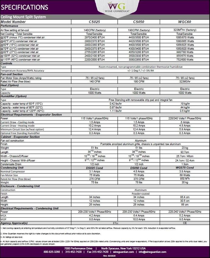
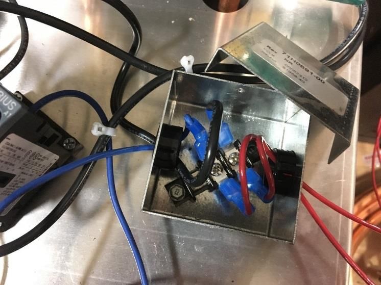
Table of Contents

Directory of Terms ..............................................................................................7
Receiving, Inspecting and Unpacking the Wine Guardian Unit .........................9
  Check for the following contents ............................................................................................................... 9
General Description ......................................................................................... 10
  The Wine Guardian Ceiling System Contains.......................................................................................... 10
     Wine Guardian Ceiling Fan Coil Unit .................................................................................................. 12
     Electrical Controls ................................................................................................................................ 12
     Condensing Unit ................................................................................................................................... 13
  Accessories and Optional Equipment....................................................................................................... 13
     Extended Compressor Warranty........................................................................................................... 13
     Remote sensors………………………………………………………………………………………..12

     Heating Coils ........................................................................................................................................ 13
     Humidifier ............................................................................................................................................ 13
     Xtreme Low Ambient (see illustrations on following page) ................................................................ 14
     Xtreme Low Ambient Illustrations....................................................................................................... 15
     Overview of the Wine Guardian Ceiling Fan Coil System .................................................................. 16
     Wine Guardian dimensions for Ceiling Systems CS025, CS050, WGC60.......................................... 16
     Condensing unit dimensions ................................................................................................................ 17
     Refrigeration Illustration of the system ................................................................................................ 18
     Magnified Image of the Condensing Unit ............................................................................................ 19
     Wiring Diagram for CS025 & CS050 .................................................................................................. 20
     Wiring Diagram for WGC60 ................................................................................................................ 21
     Wiring Diagram for DS025 and WGS40 Condensing Unit ................................................................. 22
     Wiring Diagram for DS050 and WGS75 Condensing Unit ................................................................. 23
     Ceiling System Specifications - 60Hz/50Hz Models CS025, CS050, & WGC60 ............................... 24
Safety ............................................................................................................... 25
  Safety Message Conventions.................................................................................................................... 25
     Danger .................................................................................................................................................. 25
     Warning ................................................................................................................................................ 25
     Caution ................................................................................................................................................. 25
  Lockout/Tagout Procedure ....................................................................................................................... 26
  Safety Considerations ............................................................................................................................... 26
     Safety Hazards...................................................................................................................................... 26
     Electrical Hazards................................................................................................................................. 26
     Electrical Shock Hazards...................................................................................................................... 26
     Hot Parts Hazards ................................................................................................................................. 26
     Moving Parts Hazards .......................................................................................................................... 26
  Equipment Safety Interlocks .................................................................................................................... 27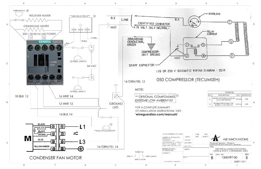
Main Power Switch .................................................................................................................................. 27
Installation ........................................................................................................ 29
  Prior to installation check system for non-visible shipping damage. ....................................................... 29
Planning the Installation .................................................................................. 30
  Addressing Items in the Planning Process................................................................................................ 30
  Performing a Pre-Installation Check ........................................................................................................ 30
Installing the Ceiling Fan Coil unit ................................................................... 31
Installing the Condensate Drain Connection .................................................. 37
  Installing the Drain Line........................................................................................................................... 37
  Priming the Condensate Pump ................................................................................................................. 37
Refrigerant piping Swagelok connection Installation Instructions .................. 37
Wiring the Fan Coil Unit for Power .................................................................. 40
Installing the Condensing Unit ........................................................................ 41
  Installation of Interconnecting Refrigerant Lines (Suction and Liquid) .................................................. 41
     Split System Interconnecting Line Sizing Chart .................................................................................. 42
  Sample Piping Configurations.................................................................................................................. 43
  Leak Checking and Evacuation Process ................................................................................................... 44
     Wiring................................................................................................................................................... 44
     Refrigerant Charging ............................................................................................................................ 46
  Determining the amount of charge ........................................................................................................... 46
  Procedures for Charging System with Head Pressure Control ................................................................. 46
     Superheat .............................................................................................................................................. 48
     Sub-Cooling ......................................................................................................................................... 48
     System Charging Amount .................................................................................................................... 48
     Split System Operations Chart ............................................................................................................. 50
Installing the Thermostat and Communication Cable ..................................... 51
Controller Specification ................................................................................... 52
Mounting the Remote Interface Controller (Wired) ......................................... 53
Mounting the Remote Interface Controller (Wireless) .................................... 54
Installation of the Wine Guardian Remote Sensor ......................................... 55
  Mounting the Wired Remote Sensor (Wired) .......................................................................................... 55
  Mounting the Remote Sensor (Wireless) ................................................................................................. 57
Remote Sensor Pairing Instructions –Multiple Sensors (Wireless) ................ 58
Standard Controller Functions ........................................................................ 59
  Alarm Codes ............................................................................................................................................. 66
Inspection and Start Up Checklists ................................................................. 68
  Receiving and Inspecting ......................................................................................................................... 68
  Handling and Installing ............................................................................................................................ 68
  Starting-up the Unit .................................................................................................................................. 68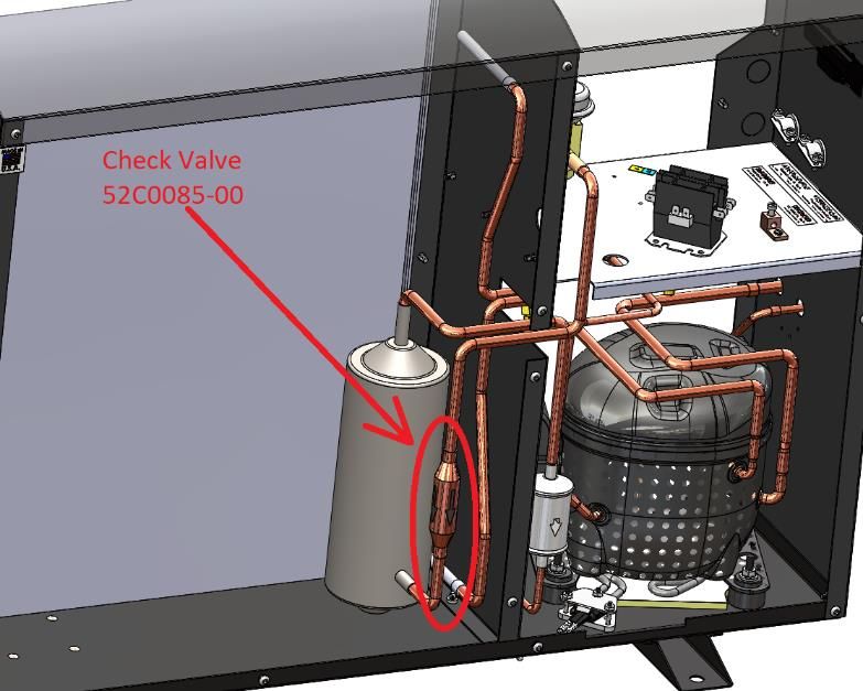
WG Split system start-up checklist……………………………………………………………68
Starting-up and Operating the Wine Guardian Split System .......................... 70
  Turn on the Unit ....................................................................................................................................... 70
  Testing the Fan ......................................................................................................................................... 70
  Running the Unit ...................................................................................................................................... 70
  Cycling the Unit ....................................................................................................................................... 71
  Setting the Remote Interface Controller ................................................................................................... 71
  Regulating the Wine Cellar Temperature ................................................................................................. 71
Maintenance .................................................................................................... 72
  General ..................................................................................................................................................... 73
  Cleaning the Condensate Drain System ................................................................................................... 74
  Cleaning the Humidifier ........................................................................................................................... 75
  Heating Coil Option ................................................................................................................................. 75
Maintenance Schedule .................................................................................... 76
  Monthly .................................................................................................................................................... 76
  Yearly....................................................................................................................................................... 76
Troubleshooting ............................................................................................... 77
  Typical start up problems ......................................................................................................................... 77
  Unit does not start up................................................................................................................................ 77
  Unit is operating and blows evaporator air but the supply air is not colder than the return air
  from the cellar......................................................................................................................................... 78
  Humidity Issues ........................................................................................................................................ 79
  Too low, without optional humidifier.................................................................................................... 79
  Humidity too low, with optional humidifier .......................................................................................... 79
  Humidity too high when unit is running but not cooling ................................................................... 79
  Humidity too high when unit is not running ........................................................................................ 79
  Humidity too high when unit is running and cooling ......................................................................... 79
  Unit is leaking water................................................................................................................................. 80
  Unit is running properly, but the sound of the unit objectionable ............................................................ 80
  High Pressure Switch has Shut the Unit Down ........................................................................................ 80
  Instructions to Reset High Pressure Switch.............................................................................................. 80
Advanced Troubleshooting .............................................................................. 80
  Evaporator Coil is Freezing...................................................................................................................... 80
  Unit cycles on and off more than 8 times/hr ...................................................................................... 80
  Replacing the blowers .............................................................................................................................. 80
Contact and Warranty Information .................................................................. 81
Warranty .......................................................................................................... 82
Note: This equipment has been tested and found to comply with the limits for a Class B digital device, pursuant to
part 15 of the FCC Rules. These limits are designed to provide reasonable protection against harmful interference in a
residential installation. This equipment generates, uses and can radiate radio frequency energy and, if not installed
and used in accordance with the instructions, may cause harmful interference to radio communications. However,
there is no guarantee that interference will not occur in a particular installation. If this equipment does cause harmful
interference to radio or television reception, which can be determined by turning the equipment off and on, the user is
encouraged to try to correct the interference by one or more of the following measures:
     • Reorient or relocate the receiving antenna.
     • Increase the separation between the equipment and receiver.
     • Connect the equipment into an outlet on a circuit different from that to which the receiver is connected.
     • Consult the dealer or an experienced radio/TV technician for help.

RSS GEN (English)
This device contains licence-exempt transmitter(s)/receiver(s) that comply with Innovation, Science and Economic
Development Canada’s licence-exempt RSS(s). Operation is subject to the following two conditions:
        1.        This device may not cause interference.
        2.        This device must accept any interference, including interference that may cause undesired
                  operation of the device.

RSS GEN (French)
L’émetteur/récepteur exempt de licence contenu dans le présent appareil est conforme aux CNR d’Innovation,
Sciences et Développement économique Canada applicables aux appareils radio exempts de licence. L’exploitation
est autorisée aux deux conditions suivantes :
          1.       L’appareil ne doit pas produire de brouillage;
          2.       L’appareil doit accepter tout brouillage radioélectrique subi, même si le brouillage est susceptible
                   d’en compromettre le fonctionnement.
Directory of Terms
Ambient Air – The surrounding area outside the wine cellar such as a room,
basement, garage or outdoors.
BTU/H – British thermal units/hour. A unit of measurement to describe the power
of heating and cooling system.
CFM – Cubic feet per minute. A unit of measurement for the amount of air handled by the
fan.
Condensate / Condensation – The water formed out of the air when it is cooled below a
certain temperature (called dew point). Often referred to as “sweating” on pipes and cold
surfaces. This water collects at the bottom of the evaporator or cooling coil and drains out of
the unit through the drain line.
Condensing Unit (Heat Rejection) – The condensing unit uses the compressor,
condenser coil and fan to remove heat from the refrigerant to the ambient air outside the
wine cellar. The word condenser refers to the condensation of the refrigerant from gas to
liquid phase.
CSA/ETL – Canadian Standards Association/Edison Testing Laboratory (product
compliance to safety standards)
F – (Degrees) Fahrenheit
Ceiling Mounted Fan Coil Unit (Evaporator Cooling) – The fan coil unit uses the
cooling coil and the fan to remove heat from the air inside the wine cellar to the refrigerant,
cooling the air and condensing moisture out of the air. The word evaporator refers to the
evaporation of the refrigerant from liquid to gas phase in the coil. The fan coil unit is ducted
to or can be placed inside the wine cellar.
Flexible Duct – Round ducts with steel reinforced plastic liners, a layer of insulation
and an outer plastic layer used to convey the air from the unit to the wine cellar or
ambient space.
Grille or Diffuser – Inlet or outlet plates to direct the airflow or protect the inside of the
unit.
Heat Gain / Loss – The amount of cooling or heating expressed in watts transferred
between the wine cellar and the ambient space. The Wine Guardian must offset this
heat/gain loss.
Inlet Air – The air returning from the wine room to the Wine Guardian fan coil.
I.D. – Inside diameter
NEC – National Electrical Code
O.D. – Outside diameter
Psig Pounds – Force per square inch gauge
Recovery – The amount of cooling the unit does to return the cellar to its set point
temperature after some new heat load is introduced, such as people or new cases of
warm wine entering the cellar.

7
Return Air - The air leaving the cellar and returning to the inlet of the fan coil. (See Inlet
Air above)
TXV – Thermal expansion valve
VAC – Volts alternating current
SP – Static pressure. Unit of measurement (inches of water column) of the pressure of
the air handled by the fan.
Set Point – The desired temperature or humidity set on the remote interface controller or
humidistat.
Supply Air - The air entering the wine cellar from the discharge of the fan coil.

8
Receiving, Inspecting and Unpacking the Wine Guardian Unit
        NOTE: Wine Guardian units are factory assembled and tested prior to shipment. The
        Wine Guardian Ducted Split System consists of two separate components, the Wine
        Guardian fan coil and condensing unit.
    Each Wine Guardian component is shipped in a corrugated box. A shipment may include one or
    more boxes containing accessories.
         ✓ Lift at the designated handhold locations only or fully support from underneath.
         ✓ Before opening, inspect the packing crates or boxes for obvious signs of damage
           or mishandling.
         ✓ Write any discrepancy or visual damage on the bill of lading before signing.
         ✓ Inspect all equipment for any sign of damage caused during transit.
         ✓ Report all visual or concealed damage to the carrier and file a claim immediately.
         ✓ Thoroughly inspect the contents for any visible damage or loose parts.
                                              IMPORTANT
        If this procedure is not followed, the shipping company may reject the claim and the
               consignee may suffer the loss. Do not return the shipment to the factory.

Check for the following contents

Ceiling fan-coil unit with:
    -     Ceiling mounted fan-coil unit
    -     Mounting flange
    -     Supply/Return Grille assembly
    -     Wine Guardian Remote Interface Controller
    -     50’ of RJ9 control cable
    -     Documentation Bag with auxiliary data plate

Condensing Unit

    -     Wine Guardian Condensing Unit

9
General Description
The Wine Guardian cooling unit is a professional grade, American-manufactured, split two-piece
climate control unit, designed specifically for the storage of wine at cellar temperatures. It is designed
for easy installation and operation. Wine Guardian uses digital electronic controls and R-134a
refrigerant. The entire Wine Guardian ceiling mount fan coil section and the condensing unit is tested at
the factory. All components are of a high quality standard commercial grade.

The entire system is approved by ETL according to UL 1995 and CSA safety standards. All wiring
complies with NEC. Each Wine Guardian ceiling mount fan coil section is furnished with a junction
box for primary power connection.
All Wine Guardian 50Hz units carry the CE mark. Each unit is furnished with a junction box for
primary power connection.

The Wine Guardian Ceiling System Contains

     1.   A Wine Guardian Ceiling fan-coil Unit with:
             ✓ A thermal expansion valve (TXV) to control the flow of refrigerant into the evaporator
               coil
             ✓ Recirc fans
             ✓ Condensate pump and float switches

10
✓ Removable, cleanable condensate pan
✓ Utility connections, junction box, humidifier, 24 volt control, com ports refrigerant pipe
drain, etc.
✓ A removable control board for ease of service
✓ Supply-air section
✓ Return-air section
✓ Mounting flange
✓ Paintable Grille
2. A Condensing Unit with:
✓ A filter dryer to keep the refrigerant clean and free of contaminants
✓ A sight glass to observe the level of refrigerant
✓ A manual reset high pressure switch on the discharge to protect the compressor from high
pressures.
✓ Auto reset low pressure switch
✓ 24-volt contactor for control of fan coil unit
✓ Outdoor enclosure
✓ Crankcase heater
✓ Low ambient refrigeration controls (see page 11 for Xtreme Low Ambient option)
11Wine Guardian Ceiling Fan Coil Unit The Wine Guardian ceiling mounted fan coil unit meets its rated capacities for total BTU/H and CFM (watts and M3/h for 50Hz) at design cellar conditions and external static pressures. The ceiling mounted fan coil is capable of rated CFM (M3/h for 50Hz) against the static pressure imposed by the diffuser. The fans are a motorized impeller type, statically and dynamically balanced, and uses permanently lubricated direct drive motors requiring no maintenance. The Wine Guardian ceiling mounted fan coil operates as air enters the device through the return air portion of the ceiling grille and is cooled by the refrigerant as it passes through the cooling coil. The cooling process causes any excess humidity in the air to condense and be captured in the drain pan which is eventually pumped out of the unit. Air then enters the fan where it is pressurized and discharged out of the unit through the supply air side of the ceiling grille. Optional heating coils are located between the cooling coil and the fan. These coils heat the air to prevent low temperatures in the wine cellar. All exterior and interior framing of the Wine Guardian is heavy gauge aluminum to prevent rust and corrosion and all coils are aluminum tubes, aluminum fins to protect against premature corrosion. The chassis is insulated with 3/4” armaflex for thermal protection. The unit uses an external drain to remove excess moisture and not reintroduce it into the cellar or ambient space. A removable, cleanable one-piece condensate drain pan with low profile pump pickup is located below the cooling coil and is easily accessible for routine maintenance. A heavy gauge galvanized steel mounting flange is supplied with each system. The mounting flange is designed to attach directly to the ceiling joists at either a 12-inch (31 cm) on-center or a 16-inch (41 cm) on-center configuration and acts to support the fan-coil chassis and ceiling grille. The mounting flange incorporates a hook mechanism to assist in chassis installation by creating a third arm to support the weight of the chassis as it is swung into place and fastened in place. All utility connections including refrigerant piping, primary electrical power, 24-volt control to the remote condensing unit, control cable connections to the remote interface controller, condensate drain connection and optional remote free-standing humidifier, if purchased with system. The ceiling diffuser is a lightweight aluminum piece that incorporates a supply and return air section divided internally to prevent short cycling. Air enters and exits the diffuser through perforated openings at its sides and draws air over sound foam insulation to reduce noise. The diffuser has an anodized finish which can be left as is…or is an ideal surface to paint to match a finished ceiling. Electrical Controls The main electrical control board and components are located on a separate divider panel at the return air section of the unit and is accessible by removal of the ceiling diffuser and condensate drain pan. The condensate pump is also mounted to the divider panel. All wiring is in accordance with the NEC. Wires are numbered and color coded to match the wiring diagrams. Each unit is provided with a pre-wired and tested remote interface controller for remote mounting within the wine cellar. The remote interface controller has multiple control functions for cooling, heating and operation. It has a fully automatic mode to switch between heating and cooling. Electric power is supplied to the unit by a single factory-furnished junction box at the utility connection side of the unit. All external controls are digital and proprietary to Wine Guardian products. Only approved communication cable and Wine Guardian controllers are suitable for proper system operation. 12
Condensing Unit
Compressors are self-lubricating, permanently sealed, hermetic reciprocating-type compressors, with
internal overload protection and capacitor start. The condensing unit includes a two-year warranty.
Compressors are mounted on rubber-in-shear isolators to reduce noise and vibration. Additional
features include a liquid line filter drier, Sporlan Head Master Controls, a liquid line receiver and
refrigerant sight glass. Each unit is housed in a painted aluminum enclosure suitable for outdoor
installation. The outdoor enclosure has adequate area for ventilation and refrigerant piping penetrations.
All units come factory-configured with low-ambient protection for exposure to cold weather down to
20 Deg F. This feature controls the system pressures to prevent evaporator coil freezing (based on head
pressure) and heats the compressor coil reservoir.
IMPORTANT
The air exhaust from the condensing unit is hot and will be 25 to 35 degrees F or 15°C to 20°C above the
entering temperature. The condensing units are rated for a maximum temperature of 115 degrees
F(46°C). The condensing units should be installed in a well-ventilated area to ensure proper air flow
across the condenser coil and to limit short cycling.
Accessories and Optional Equipment
Extended Compressor Warranty
The Wine Guardian uses only the best commercially available compressors on the market. However, since
the compressor is the single most expensive component in the unit, it is recommended that you purchase
the extended warranty option.
Remote sensors
Optional remote sensors, up to three (3), can be used with each Wine Guardian unit to better control the
wine cellar space. The remote sensors can either be wired directly to the Wine Guardian unit or they can
be installed wirelessly. Each remote sensor is a combination temperature/humidity device and is read
only, they do not display.
Heating Coils
An optional heating coil is built in and requires no additional power source. The electric heating option is
factory installed and includes primary and secondary over-temperature protection devices per UL and
NEC.
Humidifier
Another popular option for the Wine Guardian is a humidifier. The humidifier is available for split system
installation and can be retrofitted onto any existing Wine Guardian unit. Each humidifier is furnished with
a power cable connection to plug into the end of the Wine Guardian ceiling fan coil unit. It is then
controlled by the same remote interface controller that is used for the operation of the Wine Guardian unit.
The Free Standing humidifier must mount within the wine room as a secondary device. It requires a water
supply and drain for operation.
CAUTION
CAREFULLY FOLLOW THE INSTALLATION INSTRUCTIONS INCLUDED WITH THE HUMIDIFIER. REFER TO THE
INSTRUCTIONS CONTAINED IN THE BOX FOR THE HUMIDISTAT.
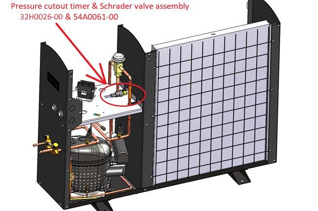
13Xtreme Low Ambient (see illustrations on following page)
The Xtreme Low Ambient options consists of factory installed refrigeration controls mounted within the
condensing unit for continuous operation of the Wine Cellar cooling unit below a temperature of 20 Deg F
(-7 Deg C). Included in the refrigeration controls are;
• Check valve – installed in the liquid line between the head pressure control valve and receiver
• Fan cycling switch
• Heater – for the receiver with thermostat control
• Adjustable low-pressure cutout timer
14Xtreme Low Ambient Illustrations
Pressure cutout timer
33C0185-00
Fig. 1
Fig. 2
15Overview of the Wine Guardian Ceiling Fan Coil System
Fig. 1
C A
Wine Guardian dimensions for Ceiling Systems CS025, CS050, WGC60
See diagram on next page for the condensing unit
Model Number CS025 (60Hz) CS050/WGC60 (60Hz)/(50Hz)
Inches Inches/cm
A –. Length 36.6 36.6/92.96
B – Width 10.18 10.18/25.86
C – Height 9.97 9.97/25.32
D – Overall height with grille 13.25 13.25/33.66
E – Grille width 18.25 18.25/46.36
F - Grille height 3.25 3.25/8.26
G – Grille/mounting plate length 43.25 43.25/109.86
Condensate drain line (ID) 0.25 0.25/0.63
Suction Line (OD) 0.37 0.37/.93
Liquid Line (OD) 0.25 0.25/0.63
CH – Condenser Height 26.07 26.07/66.22
CL – Condenser Length 12.27 12.27/31.17
CW – Condenser Width 34.0 34.0/86.36
16Condensing unit dimensions 17
Refrigeration Illustration of the system

                                                See next page for
                                                magnified image

18
Magnified Image of the Condensing Unit 19
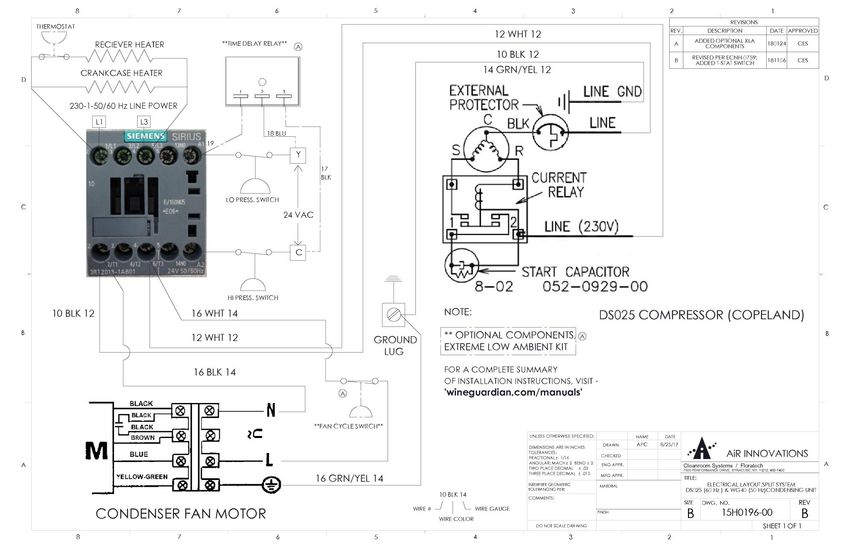
Wiring Diagram for CS025 & CS050

20
Wiring Diagram for WGC60

21
Wiring Diagram for DS025 and WGS40 Condensing Unit

22
Wiring Diagram for DS050 and WGS75 Condensing Unit

           23
Ceiling System Specifications - 60Hz/50Hz Models CS025, CS050, & WGC60 24
Safety
                                         IMPORTANT
       The equipment described in this manual uses electricity. When using this
       equipment, be sure to follow the safety procedures outlined in this manual.

Safety Message Conventions
Safety messages contained in this manual, DANGER, WARNING, and CAUTION are bold
and highlighted in red for quick identification.

Danger
A Danger message indicates an imminently hazardous situation which, if not avoided, results in
death or serious injury. Messages identified by the word DANGER are used sparingly and only
for those situations presenting the most serious hazards.

Following is a typical example of a Danger message as it could appear in the manual:

                                            DANGER
                     HIGH VOLTAGE - RISK OF SERIOUS INJURY OR DEATH
                           High voltages are present in the cabinets.
                           Before opening panels turn off all power.
                              Use the Lockout/Tagout procedure.

Warning
Following is a typical example of a Warning message as it could appear in the manual:

                                             WARNING
                    RISK OF PERSONAL INJURY OR DAMAGE TO EQUIPMENT
                         Modification to the equipment may cause injury.

Caution
A Caution message indicates a potentially hazardous situation which, if not avoided, could
result in minor or moderate injury. It may also be used to alert against unsafe practice.

Following is a typical example of a Caution message as it could appear in the manual:

                 RISK OF PERSONAL INJURY OR DAMAGE TO EQUIPMENT
     Improper installation may result in the equipment malfunctioning and a safety hazard.
       Read all of the installation instructions before installing the Wine Guardian unit.

25
Lockout/Tagout Procedure
1) Turn off system at Remote Interface Controller by hitting the on/off button
2) Turn off circuit breaker or disconnect switch to ceiling mounted unit.
3) Turn off circuit breaker or disconnect switch at condensing unit.
Safety Considerations
The equipment covered by this manual is designed for safe and reliable operation when installed
and operated within its designed specifications. To avoid personal injury or damage to equipment
or property when installing or operating this equipment, it is essential that qualified, experienced
personnel perform these functions using good judgment and safe practices. See the following
cautionary statements.
IMPORTANT
Installation and maintenance of this equipment is to be performed only by qualified
personnel who are familiar with local codes and regulations and are experienced with
this type of equipment.
Safety Hazards
Exposure to safety hazards is limited to maintenance personnel working in and around the unit.
When performing maintenance, always use the Lockout/Tagout procedure, which is described in
this chapter. Observe the maintenance safety guidelines in this manual.
Electrical Hazards
Working on the equipment may involve exposure to dangerously high voltage. Make sure you are
aware of the level of electrical hazard when working on the system. Observe all electrical warning
labels on the unit.
Electrical Shock Hazards
All power must be disconnected prior to installation and servicing this equipment. More than one
source of power may be present. Disconnect all power sources to avoid electrocution or shock
injuries.
Hot Parts Hazards
Electric resistance heating elements must be disconnected prior to servicing. Electric heaters may
start automatically. Disconnect all power and control circuits prior to servicing the unit to avoid
burns.
Moving Parts Hazards
The Motor and Blower must be disconnected prior to opening access panels. The motor can start
automatically. Disconnect all power and control circuits prior to servicing to avoid serious
injuries or possible dismemberment.
The fans are free-wheeling after the power is disconnected. Allow the fans to stop completely
before servicing the unit to avoid cuts or dismemberment.
26Rotating Fan Blades are present in the Wine Guardian unit. Sticking a hand into an exposed fan
while under power could result in serious injury. Be sure to use the Lockout/Tagout procedure
when working in this area or remove the power cord.
Equipment Safety Interlocks
There are no electrical safety lockouts installed within the unit. Primary power must be
disconnected from the units prior to working on any part of the electrical system.
Main Power Switch
An appropriately sized circuit breaker and/or disconnect switch must be installed on the primary
power source of the ceiling mounted fan-coil unit. A separate disconnect switch must be wired
to the condensing unit. Both switches must be turned off prior to servicing equipment.
Energy Type Electrical
Hazard .................................... Electrocution, electrical burns and shock
Magnitude .............................. 120 volts and 230 volts / 1phase / 60Hz (CS025 and CS050 model)
220-240 volts / 1 phase / 50Hz (WGC60 model)
Control Method...................... Circuit breaker and disconnect switch
DANGER
• Never reach into a unit while the fan is running.
• Never remove the supply/return ceiling grille while the fan is running.
• Disconnect the power before working on the unit. The unit may have more than one
power source to disconnect.
• Avoid risk of fire or electric shock. Do not expose the unit to rain or moisture.
WARNING
• Check weights to be sure that the rigging equipment can support and move the Wine
Guardian unit safely. Note any specific rigging and installation instructions located in the
Installation section of this manual.
• All supports for the unit must be capable of safely supporting the equipment’s weight and
any additional live or dead loads encountered.
• All supports for the unit must be designed to meet applicable local codes and
ordinances.
• Do not remove supply/return ceiling grille until fan impellers have completely
stopped. Fan impellers continue to turn (free-wheel) after the power is shut off.
27CAUTION
• Clean only with a dry cloth.
• Never pressurize equipment above specified test pressure. See Wine Guardian
Specification sheet on pages 24 & 25.
• Do not use the Wine Guardian near water.
• Do not block supply and/or return openings of ceiling grille. Install in accordance
with the instructions in this manual.
• Only use attachments/accessories specified by the manufacturer.
• Always operate this equipment from a 120/230 VAC, 1 phase, 60Hz power sources
only (220/240 volts / 1 phase/ 50Hz models).
• Always ground the outlet to provide adequate protection against voltage surges and
built-up static charges.
• Refer all servicing to qualified service personnel. Servicing is required when
the unit has been damaged in any way.
28Installation
CAUTION
SHARP EDGES
RISK OF SERIOUS INJURY
Sharp edges are present inside the Wine Guardian system.
Prior to installation check system for non-visible shipping damage.
29Planning the Installation
IMPORTANT
Installation of residential and commercial split systems must be performed by qualified
service technicians with proper training in the installation, start up, service, and repair
of these systems. Certification to handle refrigerants is also required.
Addressing Items in the Planning Process
✓ Where to locate the fan coil unit in the ceiling? Consider the orientation of
the unit and the supply and return grille locations relative to the room
layout.
✓ How to mount the fan coil unit? Which way to the ceiling joists run and do I have
enough clearance to flush mount the system or will it be exposed within the room.
✓ How to route the utilities to the ceiling fan-coil unit including the refrigerant
line set to the condensing unit, condensate drain, control wiring, thermostat
control cable and the optional humidifier control wire.
✓ Locate the condensing unit in a clean and well-ventilated area.
✓ Where to locate the remote interface controller and/or remote sensors?
✓ Where to run the drain line? How and where do you tie-in the line to the home or
facility
✓ Are all the parts on-site and available to complete the installation?
Performing a Pre-Installation Check
✓ Check for the properly sized breakers for both the condensing unit and fan coil
section.
✓ Is the cellar built with adequate insulation and vapor barriers?
✓ If glass is part of the wine room design is it sealed and if glass doors are used are
they sealed
✓ Is enough space available around the units for service and repair?
30Installing the Ceiling Fan Coil unit
The ceiling unit consists of three main components that are
required for proper installation — the fan-coil chassis, the
mounting flange, and the paintable ceiling grille.
The fan coil chassis incorporates a return-air section which
directs air through the evaporator coil, a supply air section
with fan shroud, dual motorized impeller fans and optional
heaters. The chassis also features a separate controls section
along with a one-piece removable condensate drip pan with
pump pick up, float switch and connection ports.
The mounting bracket is designed of heavy gauge galvanized
steel and will attach to either 16” (41 cm) on-center or 12”
(31 cm) on-center joist spacing.
The ceiling grille is the part of the unit that will be visible
in the wine room and consists of the supply-air side and the
return-air side. The exposed grille is an anodized aluminum
finish that is paintable.
31Looking at the utility connection end of the unit, the chassis
has five main connection points.
- Junction box for primary power connection
(120v/1ph/60hz or 220v/1ph/50hz.)
- Refrigerant piping connections, suction and liquid lines to
remote condensing unit.
- 24 volt control between ceiling fan-coil and remote
condensing unit.
- RJ9 control cable connection to the remote interface
controller and optional remote sensors.
- Drain line connection.
- Optional humidifier connection
When installing the Wine Guardian ceiling system it’s
important to understand the orientation of the unit, where
the supply and return are located in relation to the
connection points and how that will affect the wine room
when installed. As an example, when installing within a
glass enclosure you may not want the cold air blowing
directly onto the glass therefore determining the correct
orientation for supply/return is extremely important. Also,
utility connections are at one end of the unit ONLY so
understanding where those connections are to be made is
important.
IMPORTANT
The below photo shows the mounting flange attached directly to the joists for illustration
purposes ONLY. The mounting flange MUST be installed after the sheetrock or ceiling face
material has been installed.
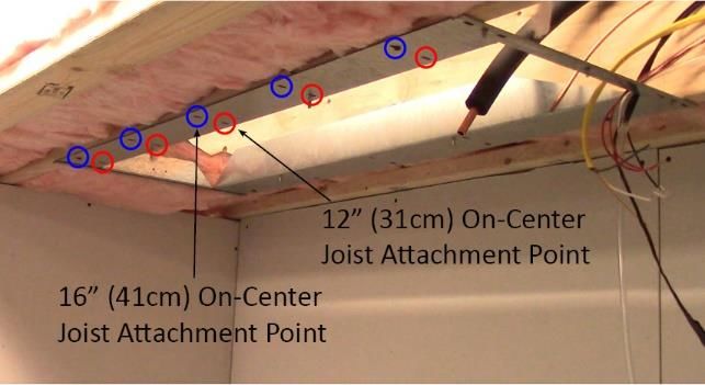
Ceiling joists are normally either 12” (31 cm) on-center or
16” (41 cm) on-center. This means that the center of
individual wooden joists are either a consistent 12” (31 cm)
or a consistent 16” (41 cm) apart from each other. The Wine
Guardian galvanized steel mounting flange will fit
comfortably between 12” (31 cm) or 16” (41 cm) on-center
ceiling joists and allow you to attach to either configuration.
32Before installing any wine cellar cooling system, it is
important to make sure the wine room is properly
constructed. Follow Wine Guardian’s “How to Build a Wine
Cellar” video for assistance.
The first step in the installation process is to route all of the
utilities to the area of the ceiling in which the Wine Guardian
Ceiling System will be mounted. Required connections:
refrigerant piping, primary power, drain line, RJ9 Control
cable, 24-volt control to condensing unit and optional
humidifier connection.
Once the ceiling has been insulated and the sheet rock or
ceiling material has been installed, clearly mark and cut-out
the opening in the ceiling where the unit will be installed. The
cut-out opening should be no larger than the following:
16” (41 cm) joist spacing = 41” (104 cm) long X 14.5” (37
cm) wide
12” (31 cm) joist spacing = 41” (104 cm) long X 10.5” (27
cm)
Make sure to take joist location into account before cutting
the hole for the unit. For old construction make every
precaution to ensure the mounting area is free and clear of
utilities prior to cutting the ceiling.
33Once the hole for the unit is cut out, place the mounting
flange up onto the ceiling with the studs pointing down and
the hinge area placed on the opposite side of the utility
connection area. Attach the mounting bracket to the ceiling
using 2 ½” flat head screws making sure to penetrate the
joists for secure attachment.
At this point you can add additional insulation to the sides
and top of the mounting area as required to ensure the
envelope is completely insulated and protected.
Now that we have the mounting bracket installed, we can
install the fan coil. The first step to installing the fan coil is
to line up the latch-end with the hook-end on the mounting
bracket. Lift the fan coil up onto the mounting bracket so
that the fan coil latch-end rests on its mating hook-end.
This latch system works as a third hand and allows you to
swing the fan-coil up into position. Swing the fan-coil
chassis up into place so that the slotted areas at either long
end of the unit slide over the threaded connections on the
mounting flange
34Fasten to the mounting bracket at the four threaded
connection points using a washer, lock washer and nut and
tighten.
Once the fan coil is in place connect the utilities to the unit.
Start with the refrigerant piping. The Wine Guardian unit
ships complete with Swagelok piping connections on the
suction line and liquid line. Follow the manufacturers
connection instructions starting on page 35 for proper
attachment.
Continue with the primary power, 24v control to
condensing unit, remote interface controller connection and
the drain. (see page 36, 37 and 38 for additional
instructions). If you ordered the Ceiling System with an
optional Free-standing humidifier, the humidifier will also
need to be connected to the unit during this step.
After all utilities are connected to the unit, fill in any voids
or holes with insulation. Closed-cell spray foam is a
common insulation method, and it provides excellent vapor
barrier and insulative properties.
35Attach the ceiling grille to the mounting flange. The
ceiling grille has a hinge at one end and two mounting
clips on the opposite end. To begin, line up the hinge-end
of the ceiling grille with the hinges on the mounting
bracket. Next, with the flat, gasketed side of the grille
facing up towards the ceiling, lift the grille up towards the
mounting flange and slide the hinges on the grille into the
hinges on the mounting flange. Once the hinge is attached
and secure, lift the opposite end of the grille up to the
mounting flange so that the grille slides over the pins
adjacent to the mounting clips. Once the ceiling grille is in
place close each clip by moving it in toward the end of the
grille.
Continue to the installation of the condensing unit as shown on
page 38 below prior to start-up of the system
CAUTION
RISK OF PERSONAL INJURY OR DAMAGE TO EQUIPMENT
Check supporting structure for load bearing capacity to support the Wine Guardian. All
supports must be designed to meet applicable local codes and ordinances. If in doubt, consult a
qualified architect, engineer or contractor.
36Installing the Condensate Drain Connection
The Wine Guardian unit provides dehumidification for the inside of the wine cellar. It cools the air
down to the dew point corresponding to the temperature setpoint of the remote interface controller. If
the vapor barrier of the wine cellar is poorly constructed or excess moisture is in the ambient area, the
unit may remove excessive amounts of moisture from the wine cellar. The moisture appears in the
condensate drain of the unit.
Installing the Drain Line
✓ The drain line must extend from the unit to an external drain or disposal site. Do not use
drain tubing any smaller than one-quarter inch inside dimension.
The Wine Guardian unit has a built-in condensate pump which has the following specifications. The
pump has the ability to pump 1.2 Gallons per day (4.5 Liters per day) of water to a maximum height
of 20’ from the ceiling unit. The pump pick-up is located within the condensate drain pan and has a
float switch which when activated turns the pump on to remove water from the drain pan. Should
water rise above the float level an auxiliary switch turns off the cooling unit and the pump will
continue to operate until the water level drops below the float switch. The cooling unit will also
remain off until excess water is below the auxiliary safety switch.
Priming the Condensate Pump
The internal pump primes itself automatically once the unit has run for a period of time and after the
unit cycles off.
Refrigerant piping Swagelok connection Installation Instructions
Swagelok tube fittings 1 in./25 mm and smaller can be installed quickly, easily, and reliably with simple
hand tools. Over 1 in./25 mm sizes require use of a hydraulic swaging unit to swage the ferrules onto the
tubing.
Safety Precautions
■ Do not bleed system by loosening fitting nut or fitting plug.
■ Do not assemble and tighten fittings when system is pressurized.
■ Make sure that the tubing rests firmly on the shoulder of the tube fitting body before tightening
the nut.
■ Use the correct Swagelok gap inspection gauge to ensure sufficient pull-up upon initial installation.
■ Always use proper thread sealants on tapered pipe threads.
■ Do not mix materials or fitting components from various manufacturers—tubing, ferrules, nuts, and
fitting bodies.
■ Never turn fitting body. Instead, hold fitting body and turn nut.
37■ Avoid unnecessary disassembly of unused fittings.
■ Use only long reducers in female Swagelok end connections.
See the instructions starting below for installation of Swagelok tube fittings, O-seal male connectors,
caps and plugs, port connectors, tube adapters, position-able elbows and tees, weld fittings, depth
marking tool, and pre-swaging tool.
Swagelok Tube Fittings Up to 1 in./25 mm
These instructions apply both to traditional fittings and to fittings with the advanced back-ferrule
geometry.
Fully insert the tube into the fitting and against the
shoulder; rotate the nut finger-tight.
High-pressure applications and high safety factor
systems: Further tighten the nut until the
tube will not turn by hand or move axially in the
fitting.
Mark the nut at the 6 o’clock position. While holding the fitting
body steady, tighten the nut one and one quarter turns to the 9
o’clock position.
For 1/16, 1/8, and 3/16 in.; 2, 3, and 4 mm tube fittings, tighten
the nut three quarter-turn to the 3 o’clock position.
38Reassembly – All Sizes
You may disassemble and reassemble Swagelok tube fittings many times.
Always depressurize the system before disassembling a Swagelok tube fitting.
Prior to disassembly, mark the tube at the back of the nut; mark a line
along the nut and fitting body flats. Use these marks to ensure that you
return the nut to the previously pulled-up position.
Insert the tube with pre-swaged ferrules into the fitting until the
front ferrule seats against the fitting body. Over 1 in./25 mm sizes:
If needed, reapply lubricant lightly to the body threads and the rear
surface of the back ferrule.
While holding the fitting body steady, rotate the nut with a wrench to
the previously pulled-up position, as indicated by the marks on the
tube and flats. At this point, you will feel a significant increase in
resistance. Tighten the nut slightly.
Do not use the Swagelok gap inspection gauge with reassembled fittings.
39Wiring the Fan Coil Unit for Power
DANGER
ELECTRICAL SHOCK HAZARD
RISK OF SERIOUS INJURY OR DEATH
The electrical outlet and wiring installation must meet the national and local
building codes.
DO:
Provide dedicated circuit and wiring for the system.
Match the wiring and breaker size to the rated load as shown on the serial plate and
in this guide. See sample serial plate illustration below.
99H0368-00
DS050
.DO NOT:
✓ DO NOT MODIFY THE ELECTRICAL WIRING WITHIN THE CEILING UNIT.
✓ Do not use extension cords.
IMPORTANT
The electrical power supply must be 115 volt AC 1 phase, 60 cycle, for model CS025 and CS050 and
220/240 volt, 1 phase, 50 cycle for model WGC60.
This cannot vary more than plus or minus 4% or damage may occur to the unit.
40Installing the Condensing Unit
• Condensing units are factory assembled with an aluminum outdoor enclosure for
protection from the elements.
• A minimum of 12 inches (30cm) is required around the perimeter of the condensing unit
for proper airflow across the coil, and to provide an adequate discharge airflow path.
Any obstructions to this airflow will result in a decrease in performance, and possibly
premature failure due to a buildup of high pressure within the system.
• The condensing unit is designed to operate in ambient temperatures ranging from
0°F-115°F (minus -18°C - 46°C), as it is supplied with many standard features to
assist full operation in this wide range.
• Mount the condensing unit above normal snowfall levels, so as to allow uninhibited winter
operation. A buildup of snow or any obstruction to airflow will result in a decrease in
performance and possible premature failure due to an increasingly high pressure within
the system.
Installation of Interconnecting Refrigerant Lines (Suction and Liquid)
NOTE: The interconnecting copper refrigerant lines shall be supplied by the installer. The
larger suction line must be fully insulated along its complete length from condensing unit
to fan coil unit. There is a factory-installed liquid line filter-drier inside the condensing unit;
therefore, no additional drier is needed for proper operation. A liquid line moisture/sight
glass is factory installed in the condensing unit to assist in monitoring the refrigerant
charge, and the state of the refrigerant in the system.
• Keep horizontal and vertical distances between the indoor and outdoor section as close as
possible to minimize refrigerant charge required. This will reduce system issues related to
oil management that can impair performance and jeopardize the compressor’s lubrication.
• Provide a one-inch pitch in suction and liquid line toward the evaporator for every 10
feet (3 meters) of run to prevent any refrigerant that condenses in the suction line from
flowing to the compressor when the unit is off. These two lines can be routed together
and wrapped together, as long as the suction line is fully insulated as previously directed.
• Suction line riser traps are not required if the riser is properly sized to maintain
refrigerant velocity. Adding a trap will only increase pressure drop.
• Prevent dips, sags, or other low spots that will trap refrigerant oil, which is an issue
especially with long horizontal runs. Use hard refrigerant copper for longer horizontal runs
to prevent potential oil return problems. (see sample piping chart on page 40)
• When sweat connections are made in the connecting lines, be sure that the inside of the
tubing is clean before installing the unit. Use a dry nitrogen bleed during brazing. Note that
compressor suction and discharge valves should be open to atmosphere no longer than 15
minutes. Compressors with POE (polyolester) oil will quickly become contaminated when
opened to atmosphere. On any installation, the use of a suction line filter, liquid line filter
drier and moisture indicator is recommended. If the suction line is larger than one-
41You can also read