Refrigerant Leak Detection System (RLDS) Installation and Operation Manual - 026-1309 Rev 12
←
→
Page content transcription
If your browser does not render page correctly, please read the page content below
Refrigerant Leak Detection System
(RLDS) Installation and Operation
Manual

  026-1309 Rev 12
Emerson Digital Cold Chain
                                               Commercial & Residential Solutions
                                              1065 Big Shanty Road NW, Suite 100
                                                       Kennesaw, GA 30144 USA
                                                   770-425-2724 • 1-800-829-2724
                                                        www.climate.emerson.com
                                 Email: ColdChain.TechnicalServices@Emerson.com

CE/FCC Compliance Notice Information
Class A compliance for RLDS under CE Requirements. Meets Part 15 Subpart B
requirements of the FCC Rules. In a domestic environment this product may cause
radio interference in which case the user may be required to take adequate measures.
ETL, report no 3151009LAX-001 to:
ANSI/UL 61010-1
CAN/CSA 22.2 No 61010-1 & CE Mark

READ ALL INSTRUCTIONS CAREFULLY
If the equipment is not used in the manner specified by the manufacturer, the protection
provided by the equipment may be impaired.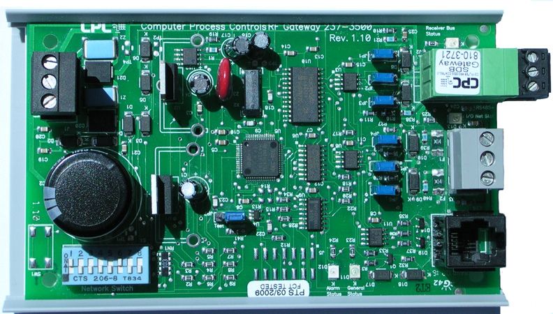
Contents
1 INTRODUCTION.......................................................................................................................................................... 1
1.1. HOW TO USE THIS MANUAL ........................................................................................................................................ 1
1.2. NOTES ........................................................................................................................................................................... 1
1.3. SAFETY PRECAUTIONS .................................................................................................................................................. 1
1.3.1. AC Power Supply .................................................................................................................................................. 1
1.3.2. Protective Grounding............................................................................................................................................ 1
1.3.3. Explosive Atmosphere ........................................................................................................................................... 1
1.3.4. Proper Exhaust Venting ........................................................................................................................................ 1
1.3.5. Working Inside Instrument.................................................................................................................................... 1
1.3.6. Misuse and Modifications to the Instrument......................................................................................................... 2
1.3.7. In Case of Malfunction.......................................................................................................................................... 2
1.3.8. RLDS Fusing ......................................................................................................................................................... 2
1.3.9. Installation Category ............................................................................................................................................ 2
1.3.10. Altitude Limit...................................................................................................................................................... 2
1.3.11. Cleaning ............................................................................................................................................................. 2
1.4. WARNING AND CAUTION CONVENTIONS ..................................................................................................................... 2
1.4.1. Warning................................................................................................................................................................. 2
1.4.2. Caution.................................................................................................................................................................. 2
1.4.3. Important............................................................................................................................................................... 2
2 FUNCTIONAL OVERVIEW ....................................................................................................................................... 3
2.1. GENERAL DESCRIPTION ................................................................................................................................................ 3
2.2. COMMUNICATION OPTIONS .......................................................................................................................................... 3
2.3. UNDERSTANDING MONITORING LEVELS ...................................................................................................................... 4
2.4. RESPONSE TO THE PRESENCE OF MULTIPLE REFRIGERANTS ....................................................................................... 4
2.5. SUGGESTED LOCATION OF SAMPLING POINTS ............................................................................................................. 4
2.6. RLDS HARDWARE SPECIFICATIONS............................................................................................................................. 6
3 RLDS INSTALLATION ............................................................................................................................................... 8
3.1. RLDS - INSTALLATION CONSIDERATIONS ................................................................................................................... 8
3.1.1. Warnings and Cautions......................................................................................................................................... 8
3.1.2. Inspection .............................................................................................................................................................. 8
3.1.3. Monitor Location .................................................................................................................................................. 8
3.1.4. Mounting Instructions ........................................................................................................................................... 9
3.2. RLDS - CONNECTING GAS SAMPLE LINES ............................................................................................................... 10
3.2.1. Overview ............................................................................................................................................................. 10
3.2.2. Tubing Considerations ........................................................................................................................................ 10
3.2.3. Connecting Purge Line ....................................................................................................................................... 11
3.2.4. Connecting Exhaust Line .................................................................................................................................... 11
3.2.5. Connecting Sample Intake Lines......................................................................................................................... 11
3.2.6. Considerations .................................................................................................................................................... 12
3.3. INSTALLING AN OPTIONAL SPLITTER KIT .................................................................................................................. 13
3.3.1. Connecting the Water Trap................................................................................................................................. 13
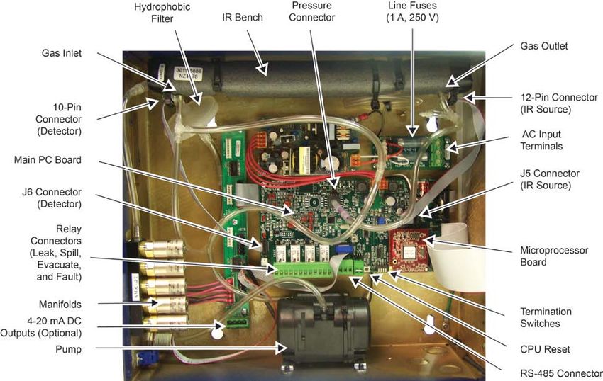
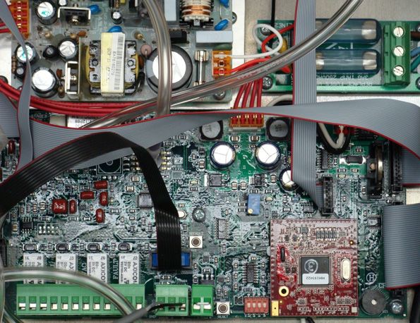
3.4. RLDS INTERIOR COMPONENTS .................................................................................................................................. 14
3.5. RLDS ELECTRICAL WIRING ....................................................................................................................................... 14
3.5.1. Warnings and Cautions....................................................................................................................................... 15
4 CONNECTING COMMUNICATION DEVICES ................................................................................................... 16
4.1. E2 MODBUS DIRECT SUPPORT FOR RLDS .............................................................................................................. 16
4.1.1. Network Connection to E2 .................................................................................................................................. 16
•v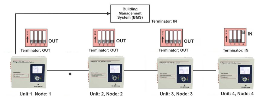
4.1.1.1. COM Port Associations - E2 Versions 3.xx and Below ................................................................................................... 16
4.1.1.2. COM Port Associations - E2 Versions 4.0 and Above..................................................................................................... 16
4.1.1.3. E2 Termination ................................................................................................................................................................. 17
4.1.2. E2 Setup of RLDS................................................................................................................................................ 17
4.1.2.1. Set Up Network Ports ....................................................................................................................................................... 17
4.1.2.2. Add and Connect RLDS .................................................................................................................................................. 17
4.2. E2, EINSTEIN, AND REFLECS CONTROLLERS (THE RLDS GATEWAY BOARD) ....................................................... 19
4.2.1. Powering the Gateway Board ............................................................................................................................. 19
4.2.2. Gateway Board Networking ................................................................................................................................ 20
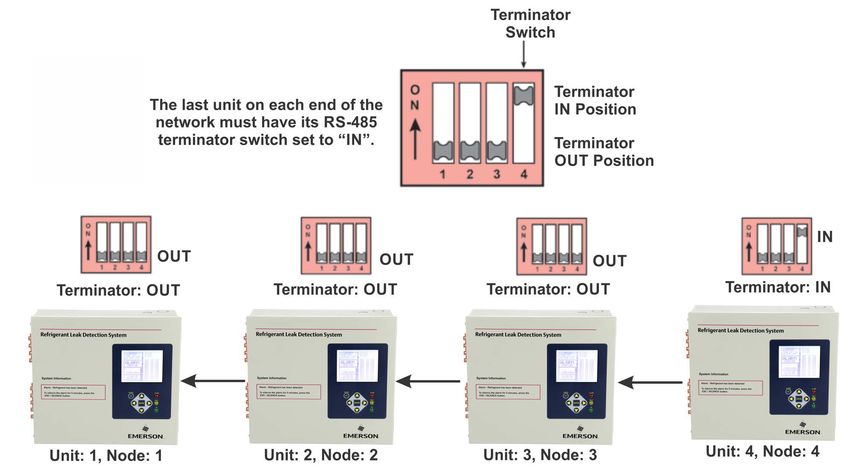
4.2.2.1. Changing Terminator Switch Settings.............................................................................................................................. 20
4.2.2.2. RLDS Node Address ........................................................................................................................................................ 20
4.2.3. Connecting to an E2, Einstein, or REFLECS Site Controller............................................................................. 21
4.2.4. Connecting the Gateway Board to the E2, Einstein, or REFLECS Network ...................................................... 21
4.2.4.1. Wire Connection .............................................................................................................................................................. 21
4.2.4.2. Setting the Board Numbering Dip Switch ....................................................................................................................... 22
4.2.4.3. Setting the Baud Rate Dip Switches ................................................................................................................................. 23
4.2.4.4. Setting the RS485 I/O Termination Jumpers .................................................................................................................... 23
4.2.5. Gateway Board Status LEDs............................................................................................................................... 24
4.2.5.1. The General Status LED ................................................................................................................................................... 24
4.2.5.2. The Alarm LED ................................................................................................................................................................ 24
4.2.5.3. RS485 I/O Network Status LED....................................................................................................................................... 24
4.2.5.4. Receiver Bus Network Status LED................................................................................................................................... 24
4.3. INTEGRATING WITH BUILDING MANAGEMENT SYSTEMS ........................................................................................... 24
4.4. CONNECTING TO A BUILDING MANAGEMENT SYSTEM ............................................................................................... 25
4.5. TERMINATING MULTIPLE MONITORS ......................................................................................................................... 26
4.6. PC SOFTWARE ............................................................................................................................................................ 27
4.6.1. Operation ............................................................................................................................................................ 27
4.6.2. Saving and Sending Programs ............................................................................................................................ 27
4.6.3. Trend Data .......................................................................................................................................................... 28
4.6.4. Converting the TREND Text File to a Microsoft Excel File ............................................................................... 28
4.6.5. Saving and Printing Screens and Logs ............................................................................................................... 28
4.6.6. USB Type Laptops............................................................................................................................................... 28
4.7. OPTIONAL CURRENT LOOP INTERFACES .................................................................................................................... 28
4.7.1. Optional 4–20 mA DC Outputs ........................................................................................................................... 28
4.7.2. 4-20 mA DC Connections.................................................................................................................................... 29
5 RLDS - CONNECTING EXTERNAL ALARMS..................................................................................................... 31
5.1. OVERVIEW .................................................................................................................................................................. 31
5.2. CONNECTION............................................................................................................................................................... 31
6 PROGRAMMING SETUP AND UI NAVIGATION FOR RLDS - DISPLAY SCREENS.................................. 33
6.1. INITIAL POWER UP...................................................................................................................................................... 33
6.2. DATA DISPLAY SCREEN.............................................................................................................................................. 33
6.3. NAVIGATE TO THE FIRST SETUP SCREEN ................................................................................................................... 33
6.4. NAVIGATE TO THE SECOND SETUP SCREEN ............................................................................................................... 34
6.5. LOCATION ................................................................................................................................................................... 34
6.6. NUMBER OF ZONES INSTALLED .................................................................................................................................. 34
6.7. ALARM ACKNOWLEDGE (ACK) - MODE ..................................................................................................................... 34
6.8. AUDIBLE ALARM ........................................................................................................................................................ 35
6.9. ZONE HOLD ................................................................................................................................................................ 35
6.10. DETECTION LIMIT ..................................................................................................................................................... 35
6.11. LOOP MODE .............................................................................................................................................................. 35
6.12. LOOP2 FACTOR ........................................................................................................................................................ 35
6.13. RE-ZERO MODE ....................................................................................................................................................... 36
6.14. NAVIGATING TO THE THIRD SETUP SCREEN ........................................................................................................... 36
vi • RLDS I&O Manual 026-1309 Rev12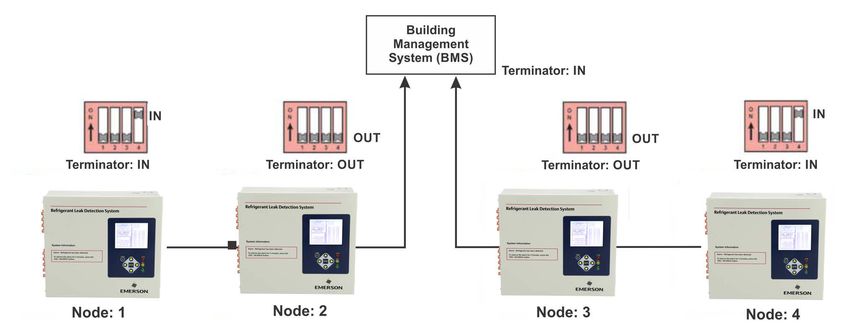
6.15.     BAUD RATE ..............................................................................................................................................................                   36
6.16.     NODE ADDRESS .......................................................................................................................................................                       36
6.17.     PASSWORD ...............................................................................................................................................................                   37
6.18.     ADDITIONAL SERVICE FEATURES ............................................................................................................................                                   37
6.19.     SERVICE TIMEOUT ....................................................................................................................................................                       37
6.20.     DEG DIGIPOT ...........................................................................................................................................................                    37
6.21.     NODE ADDRESS ........................................................................................................................................................                      38
6.22.     SENSOR TEMPERATURE COEFFICIENT (FOR FACTORY USE ONLY) .........................................................................                                                            38
6.23.     PASSWORD ................................................................................................................................................................                  38
6.24.     ACQUIRING TEMPERATURE COEFFICIENT (FACTORY USE ONLY) ..........................................................................                                                            38
6.25.     R DIGIPOT ................................................................................................................................................................                 38
6.26.     ESTABLISHING THE CO2 BASELINE .........................................................................................................................                                    38
7 GENERAL OPERATION OF RLDS - UI................................................................................................................. 40
7.1. FUNCTIONAL OVERVIEW ............................................................................................................................................                                40
7.2. THE ZONE SETUP SCREEN ..........................................................................................................................................                                40
   7.2.1. Location ..............................................................................................................................................................                    40
   7.2.2. Gas/Refrigerant Type ..........................................................................................................................................                            40
   7.2.3. Distance + EXH ..................................................................................................................................................                          40
   7.2.4. Temperature at Zone...........................................................................................................................................                             40
   7.2.5. Current Detection Reading .................................................................................................................................                                40
   7.2.6. Log Interval.........................................................................................................................................................                      41
7.3. NAVIGATING TO THE SECOND ZONE SETUP SCREEN .................................................................................................                                                    41
   7.3.1. Leak Level ...........................................................................................................................................................                     41
   7.3.2. Spill Level............................................................................................................................................................                    41
   7.3.3. Evacuation Level.................................................................................................................................................                          41
   7.3.4. Resetting the Peak PPM Value ...........................................................................................................................                                   41
7.4. ALARM CONDITIONS ..................................................................................................................................................                             41
7.5. FAULT CONDITIONS ....................................................................................................................................................                           42
7.6. ALARMS ......................................................................................................................................................................                   42
   7.6.1. Functional Overview...........................................................................................................................................                             42
   7.6.2. Responding to Alarms .........................................................................................................................................                             42
   7.6.3. Alarm Detail Screen............................................................................................................................................                            42
   7.6.4. Acknowledging Alarms .......................................................................................................................................                               43
   7.6.5. Silencing an Alarm..............................................................................................................................................                           43
   7.6.6. Clearing the Alarm Even Log .............................................................................................................................                                  44
7.7. SYSTEM FAULTS .........................................................................................................................................................                         44
   7.7.1. Functional Overview...........................................................................................................................................                             44
   7.7.2. Navigating to the Fault Screen ...........................................................................................................................                                 45
        7.7.2.1.     Critical Faults................................................................................................................................................................... 45
        7.7.2.2.     Non-Critical Faults ......................................................................................................................................................... 46
   7.7.3. Reset to Factory Default Settings........................................................................................................................                                  46
   7.7.4. Clearing System Faults .......................................................................................................................................                             46
   7.7.5. Viewing Fault Log...............................................................................................................................................                           47
   7.7.6. Viewing Flow Log ...............................................................................................................................................                           47
7.8. THE TREND SCREEN ...................................................................................................................................................                            47
   7.8.1. Navigating to the Trend Screen ..........................................................................................................................                                  47
7.9. THE CALIBRATION SCREEN ........................................................................................................................................                                 48
   7.9.1. Overview .............................................................................................................................................................                     48
   7.9.2. Navigating to the Calibration Screen .................................................................................................................                                     48
   7.9.3. Calibration Procedure ........................................................................................................................................                             48
   7.9.4. Adjusting Calibration Factor..............................................................................................................................                                 49
   7.9.5. CO2 Atmospheric Concentration
   (RLDS-CO2 Units Only) .................................................................................................................................................                           49

                                                                                                                                                                                                  • vii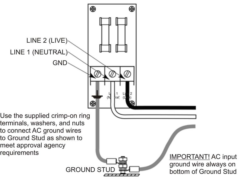
7.9.6. Programming New Gases.................................................................................................................................... 50
7.10. ZONE HOLD MODE ................................................................................................................................................... 50
7.11. THE DIAGNOSTIC SCREEN ....................................................................................................................................... 51
   7.11.1. Navigating to the Diagnostic Screen................................................................................................................ 51
   7.11.2. Diagnostic Screen Overview ............................................................................................................................ 52
8 QUICK SETUPS FOR HAND-HELD TERMINAL (HHT).................................................................................... 53
8.1. TIME/DATE SETUP ...................................................................................................................................................... 53
8.2. ZONE SETUP ................................................................................................................................................................ 53
   8.2.1. General Configuration 1 Screen ......................................................................................................................... 53
   8.2.2. General Configuration 2 Screen ......................................................................................................................... 54
   8.2.3. Zone Config Screen 1 .......................................................................................................................................... 54
   8.2.4. Zone Config Screen 2 .......................................................................................................................................... 55
8.3. STATUS OPTION SCREEN ....................................................................................................................................... 55
   8.3.1. Zone Status Screen .............................................................................................................................................. 55
   8.3.2. General Controller (CTRL STATUS) Screen ...................................................................................................... 56
9 HAND-HELD TERMINAL (HHT) FOR USE WITH THE GATEWAY AND RLDS CONTROLLER ........... 57
9.1.     HHT KEY OPERATIONS ............................................................................................................................................. 57
10 MAIN SCREENS ....................................................................................................................................................... 58
10.1. HOME SCREEN (F1 SCREEN).................................................................................................................................... 58
10.2. RLDS ENABLE SCREEN ........................................................................................................................................... 58
10.3. SELECT RLDS SCREEN (F2 SCREEN).................................................................................................................... 58
10.4. OPERATION SELECT (OPTION) SCREEN ................................................................................................................ 59
  10.4.1. RLDS STATUS (STATUS OPTION) Screen..................................................................................................... 59
  10.4.2. RLDS FAULTS (SYSTEM FAULTS) screen..................................................................................................... 59
  10.4.3. RLDS Configuration Option (CONFIG OPTION) Screen............................................................................... 60
  10.4.4. General Configuration 1 Screen ...................................................................................................................... 60
  10.4.5. General Configuration 2 Screen ...................................................................................................................... 60
  10.4.6. Zone Config Screen 1 ....................................................................................................................................... 61
  10.4.7. Zone Config Screen 2 ....................................................................................................................................... 61
  10.4.8. Time/Date Screen ............................................................................................................................................. 62
  10.4.9. Calibrate Gas Screen 1 .................................................................................................................................... 62
  10.4.10. Calibrate Gas Screen 2 .................................................................................................................................. 62
  10.4.11. Calibrate Gas Screen 3 .................................................................................................................................. 62
       10.4.11.1. Calibrate Gas Screen 3 Continued ............................................................................................................................... 63
10.5. STATUS OPTION SCREEN .................................................................................................................................... 63
  10.5.1. Zone Status Screen .......................................................................................................................................... 63
  10.5.2. General Controller (CTRL STATUS) Screen .................................................................................................. 63
  10.5.3. DIAGNOSTICS Screen 1: Sensor Data Register ............................................................................................ 64
  10.5.4. Screen 2: Sensor Data Register ....................................................................................................................... 64
  10.5.5. Screen 3: Sensor Data Register ....................................................................................................................... 64
  10.5.6. Screen 4: Sensor Data Register ....................................................................................................................... 65
  10.5.7. Screen 5: Sensor Data Register ....................................................................................................................... 65
  10.5.8. Screen 6: Sensor Data Register ....................................................................................................................... 65
  10.5.9. Screen 7: Communication Statistics................................................................................................................. 65
11 RLDS SETUP ON REFLECS, E2, EINSTEIN, AND SUPERVISORY CONTROLLERS ............................... 66
11.1. REFLECS SETUP FOR RLDS ................................................................................................................................... 66
11.2. E2 VERSION 3.01 AND BELOW SETUP FOR RLDS (WITHOUT GATEWAY)................................................................ 66
11.3. EINSTEIN SETUP FOR RLDS ..................................................................................................................................... 68
11.4. SUPERVISORY CONTROLLER SETUP FOR RLDS ...................................................................................................... 68
  11.4.1. Adding Application........................................................................................................................................... 68

viii • RLDS I&O Manual                                                                                                                                      026-1309 Rev12
11.4.2.      Edit Application ...............................................................................................................................................       69
   11.4.3.      General.............................................................................................................................................................   69
   11.4.4.      Zone Setup........................................................................................................................................................     69
   11.4.5.      Zone Alarms Leak/Spill/Evac...........................................................................................................................                 69
12 RLDS MAINTENANCE ........................................................................................................................................... 71
12.1. WARNINGS AND CAUTIONS .....................................................................................................................................                      71
12.2. REPLACEMENT PARTS OVERVIEW ............................................................................................................................                          71
12.3. REPLACEMENT PARTS AND OPTIONAL ACCESSORIES ..............................................................................................                                        73
12.4. TROUBLESHOOTING ..................................................................................................................................................               74
APPENDIX A: RECOMMENDED REFRIGERANT GAS ALARM SETTINGS.................................................... 77
APPENDIX B: MODBUS GAS ENUMERATION ....................................................................................................... 80
APPENDIX C: FAULT CODES .................................................................................................................................... 83
APPENDIX D: SYSTEM MENU MAP .......................................................................................................................... 85

                                                                                                                                                                                   • ix
1         Introduction                                     It is highly recommended that the RLDS be placed on
                                                           a separate circuit (with UPS or surge protection) and
                                                           be connected directly to the AC power source.
                                                           A switch or circuit breaker rated 1.0 A, 250 VAC,
                                                           with a minimum terminal spacing of 3.0 mm must be
                                                           attached to the monitor’s AC power leads. This
1.1. How to Use This                                       switch must also be located in close proximity to the
                                                           monitor, and be within easy reach of the operator.
     Manual                                                This switch should also be clearly marked as the
                                                           monitor’s type of equipment.
Thank you for investing in an Emerson Multi-Zone
Gas Monitor. To assure operator safety and the proper          • A switch or circuit-breaker must be included in the
                                                                 building installation
use of the monitor, please read this manual. It
provides important information on the installation,            • The switch must be in close proximity to the
operation, maintenance, and servicing of the monitor             equipment and within easy reach of the
                                                                 operator
and display module.This manual provides important
information on how to install, operate, and service the        • The switch must be clearly marked as the
                                                                 disconnecting device for the equipment
RLDS.
Please read this manual carefully before use.              1.3.2. Protective Grounding
If you have a working knowledge of refrigerant             Under no circumstances should the RLDS be
monitors, you will find this manual useful as a            operated without connection to a protective ground.
reference tool. If you are new to the use of refrigerant   Doing so poses a potential shock hazard and is also a
monitors, this document is educational in the              violation of electrical safety standards applicable to
principles of gas detection and the proper operation of    this type of equipment.
this device.
                                                           1.3.3. Explosive Atmosphere
1.2. Notes                                                 Do not operate this equipment in the presence of
                                                           flammable liquids, vapors, or aerosols. Operation of
Emerson reserves the right to change the operation or      any electrical instrument in such an environment
specifications of this instrument at any time without      constitutes a safety hazard.
notice.
                                                           1.3.4. Proper Exhaust Venting
If any errors or ambiguities are discovered in this
manual, promptly inform Emerson.                           It is imperative that the exhaust port on this
                                                           instrument be properly vented as described in this
No part of this manual may be reproduced or                manual. Failure to do so constitutes a safety hazard.
recreated, in any form or by any means, without the
express prior permission of Emerson.                       1.3.5. Working Inside Instrument
                                                           Extreme care should be exercised when accessing the
1.3. Safety Precautions                                    interior of the monitor. Only qualified electrical
                                                           maintenance personnel should perform connections
                                                           and adjustments. Always de-energize the power
1.3.1. AC Power Supply                                     supply before opening the monitor’s enclosure.
Ensure the source voltage matches the voltage of the
product before energizing the equipment.
The RLDS uses a universal power supply that is
capable of accepting inputs of 100 to 240 VAC, 50/60
Hz. The monitor’s power consumption is 20 Watts.

How to Use This Manual                                                                              Introduction • 1
1.3.6. Misuse and Modifications to
the Instrument 1.4. Warning and Caution
The protection provided by the monitor may be
impaired if the monitor is used in a manner not
Conventions
specified by Emerson. Modifications to this monitor, When used in this manual or as labeled on the gas
not expressly approved, will void the warranty. monitor, the following hazard symbols and/or
associated words are defined as follows.
1.3.7. In Case of Malfunction
Do not continue to use this equipment if there are any 1.4.1. Warning
symptoms of malfunction or failure. In the case of This symbol and/or the use of the word WARNING
such occurrence, de-energize the power supply and indicates a potential hazard from electrical shock
contact a qualified repair technician or the nearest associated with the use of this equipment. It calls
Service Center. ONLY the provided knockouts are to attention to a procedure, practice, condition, or the
be used for electrical and communication wiring. like, which if not correctly performed or adhered to,
Drilling into the box will void the warranty. could result in death or serious injury.
1.3.8. RLDS Fusing
WARNING:
1AMP, 250VAC
F1, F2 FAST ACTING
(Type “F”)
Table 1-1 - Fusing Requirements 1.4.2. Caution
1.3.9. Installation Category This symbol and/or use of the word CAUTION in
this manual denotes a potential hazard associated with
Installation Category II, Pollution Degree II, as the use of this equipment. It calls attention to a
defined by UL. procedure, practice, condition, or the like, which if
not correctly performed or adhered to, could result in
1.3.10. Altitude Limit minor or moderate bodily injury, and damage to the
RLDS 6,562 ft (2,000 m) equipment.
1.3.11. Cleaning CAUTION:
If, during period maintenance inspection it
becomes necessary to clean the outside of the case,
use a DRY CLOTH. To avoid shock hazard and/or
equipment damage, DO NOT USE SOAP AND 1.4.3. Important
WATER.
The use of the word IMPORTANT in this manual
calls attention to a procedure, practice, condition, or
the like, which if not correctly performed or adhered
to, could result in incorrect performance of or damage
to the equipment and may void the warranty.
IMPORTANT:
2 • RLDS I&O Manual 026-1309 Rev122 Functional All 800# models of the RLDS come with the number
of line-end filters (plus one extra) to match the
Overview number of zones for each model.
2.1. General Description
Gas monitors are specified to support compliance to
federal, state and local safety codes governing
emissions. Avoiding significant refrigerant loss
reduces equipment replacement costs, maintains
equipment efficiency, promotes safety, and protects
the environment.
The RLDS provides for the continuous monitoring of
refrigerant gas levels in up to 16 separate test zones or
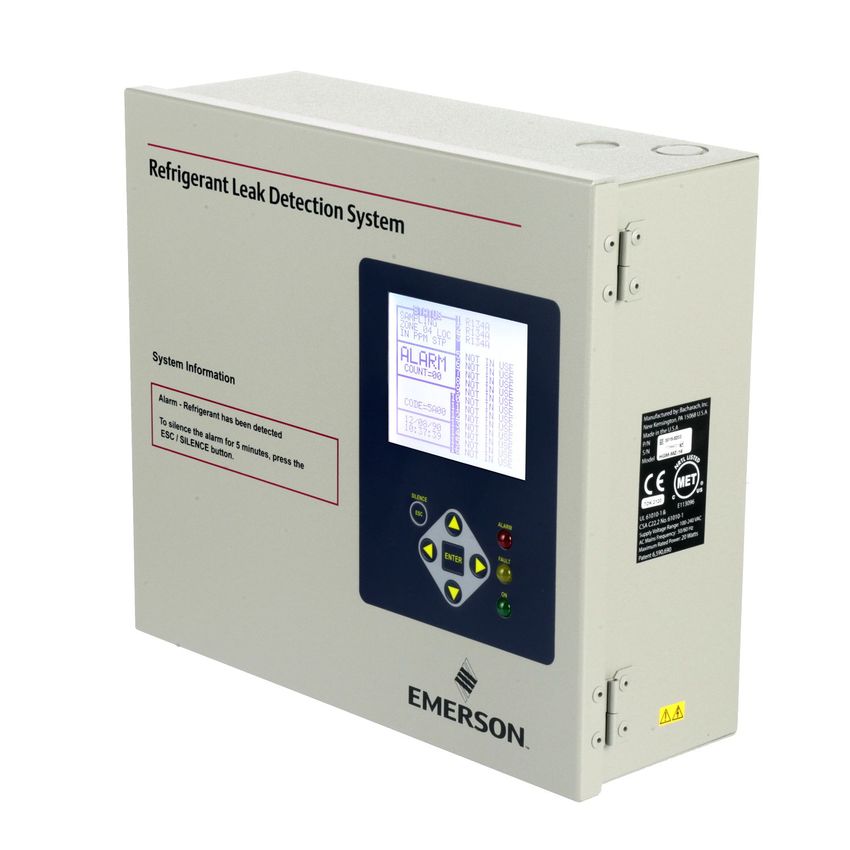
channels. The instrument is easily programmed to Figure 2-1 - RLDS Front View
monitor a variety of gases (dependent on the
particular model) and independent leak (small), spill
(medium), and evacuation (large) levels may be
designated for each zone. The instrument also retains 2.2. Communication
a log of previous readings that can be easily accessed
for analysis.
Options
An audible alarm and front panel indicators are The RLDS features full two-way communications via
provided to signal alarm and fault conditions, and an RS485 interface. MODBUS RTU is the
relay contacts are provided that can be used to trigger communication protocol standard and can be
external alarm devices in the event of a system fault, connected directly to an E2 or Supervisor controller.
or if a leak (small), spill (medium), or evacuation
The instrument can be connected directly to a
(large) level of gas is detected. The system also may
Building Management System or it may be operated
be fitted with an optional two-channel 4-20mA
as a stand-alone system. An RS-232C port is also
current loop board for connection to remote
provided for connection to a PC. This enables the
monitoring equipment.
monitor to be set up from a personal computer.
The RLDS requires only minor periodic maintenance
Please refer to Section 4, Connecting Communication
such as the occasional replacement of filters. The
Devices for a more complete discussion of
monitor incorporates active diagnostics that
communication protocols.
continuously check the system for proper operation.
A front panel indicator is provided to alert an operator
of system malfunctions, and fault codes are generated
that enable the user to identify the cause of the fault.
General Description Functional Overview • 3same sampling zone, you should carefully consider
which refrigerant compound you program the unit to
2.3. Understanding monitor.
Monitoring Levels
Effective use of this instrument requires an 2.5. Suggested Location of
understanding of what constitutes reasonable alarm
setpoints for the type of gases being monitored. Sampling Points
All AC&R systems leak some refrigerant. Refrigerant At the point of origin of a refrigerant leak, the gas is
manufacturers define allowable exposure levels and nearly pure (highly concentrated). As the refrigerant
threshold limit values in units of parts per million is dispersed into the air, the gas molecules diffuse,
(PPM). In a good “tight” installation these causing a dilution of the original concentration. The
background levels will be acceptably low and often RLDS measures the refrigerant concentration at the
do not require corrective action. You can reduce sample collection point, so if the termination of the
nuisance alarms and needless service calls if the alarm collection line is not at the exact point of the
levels are set at practical limits. refrigerant leak, the unit will read a diluted mixture of
Recommended monitoring levels based on the refrigerant gas and air.
compliance to ANSI/BSR ASHRAE 15-2007 and Gases of interest may be heavier or lighter than air
ASHRAE Safety Code 34-2007 have been developed and may collect above or below the point of the leak.
and are listed in Appendix A: Recommended Therefore sampling point placement is critical and
Refrigerant Gas Alarm Settings on page 77. must take into account properties of the target gas and
Setting the unit at these recommended alarm levels air flow within the space.
will satisfy the needs of most users. However, the Leak Detector Gas Type Sampling Point
PPM levels generated by system leaks into the Location
environment are greatly influenced by the volume of Multi-Zone Halogen Mount sampling
air in the sampling area, air circulation, size of the points 6-18 inches
leak, distance to the monitoring point, and a host of above floor
other variables. In some cases the set points may need Multi-Zone CO2 (Carbon Mount sampling
to be adjusted either up or down to achieve effective Dioxide) points 4-6 feet above
monitoring. Please contact your representative (770- floor (breathing zone)
425-2724) for assistance in obtaining these levels.
Table 2-1 - Sampling Point Locations
DO NOT block any of the zones. Unused zones may
2.4. Response to the be disabled by setting the distance parameter to zero
feet in the zone setup screen.
Presence of Multiple
The RLDS should be centrally located in the
Refrigerants mechanical room and be readily accessible for easy
visual monitoring and servicing. The combined
The RLDS is a refrigerant level monitor, not a gas length of sample tubing, plus exhaust tubing, should
analyzer. You must program the monitor to test for a not exceed 1200 feet (366 meters) for any zone. The
specific refrigerant in each zone, and it will only fresh air purge line should draw from an area that does
return accurate concentration readings for that not contain any gas other than fresh air. The exhaust
particular refrigerant. If a leak occurs of another line should run to an outside location if possible.
refrigerant gas type, the monitor may return incorrect
readings.
NOTE: The combined length of the purge line
Most applications only require detection of a single and the exhaust line cannot exceed 500 feet
refrigerant and the problems that are associated with (152.4 meters).
monitoring multiple gases are rarely an issue. If there
is a possibility of multiple refrigerants leaking in the
Ideally, two to three pick up points spaced around
each chiller will provide sufficient coverage. It may
4 • RLDS I&O Manual 026-1309 Rev12be necessary to perform a “smoke” test of the
mechanical room to determine the best locations. The
smoke test would provide the pattern of air currents
present in the mechanical room.
The RLDS should be kept dry. When used in a wet or
humid area, it is highly recommended to use the
optional water stop accessory to avoid internal
damage.
NOTE: For information about using the
RLDS in wet locations, see Section 3.2.6.,
Considerations.
Suggested Location of Sampling Points Functional Overview • 52.6. RLDS Hardware Specifications
Hardware Specifications
Product Type Multiple refrigerant gases and multiple area monitoring system for low level
continuous monitoring of CFC, HCFC, and HFC refrigerant gases used in most
commercial refrigeration systems. System design supports compliance to the
refrigerant monitoring requirements of ANS/BSR ASHRE 15-2007 and
ASHRAE Safety Code 34-2007.
Coverage 4-point standard, expandable to 16 points in 4-point increments
Detector Type Infrared Non-Dispersive
CFC: R-11, R-12, R-113, R-114, R-502, HFP
HFC: R125, R-134a, R236FA, R245Fa, R32, R-404a (HP62), R-407a,
R-407c (AC9000), R-407F, R-410a (AZ20), R422a, R422d, R427a,
R-507 (AZ50), R-508b (SUVA95)
Gas Library:
HCFC: R-123, R-124, R21, R-22, R227, R-23, R-401a (MP39), R-402a
(HP80), R-402b (HP81), R-408a, R-409a, R-500, R-503
Halon: H1211, H1301, H2402
Other: FA188, FC72, H1234YF, H1234ZE, N1230, N7100, N7200,
N7300, N7600, R424A, R426A, R438A, CUSTOM
Sensitivity All gases 1 PPM
Measuring Range All gases 0 to 10,000 PPM
Accuracy* Most gases ±1PPM ±10% of reading from 0-1000 PPM (R11, R22, and R113
±10 PPM ±15% of reading 0-1000 PPM)
*At reference environmental conditions (77°F/25°C, 45% RH
non-condensing, 1 ATM)
Front Panel 3 Indicator lights:
• Green = Monitor is powered on. LED glows during normal operation; flashes
when unit is in warm-up mode
• Red = Alarm. LED flashes when any point has exceeded the alarm setting
• Yellow = Fault. LED flashes when there is a system fault
Size/Weight 12.23”H x 13.7”W x 4.96”D (31.06 cm x 34.80 cm x 12.60 cm) / 15 lbs.
Temperature Drift ±0.3% of reading per degrees C
Sampling Mode Automatic or manual (hold)
Re-Zero Auto or on zone change
Response Time 5 to 315 seconds – depending on air line length and number of zones
System Noise Less than 40dB(A) @ 10 feet (3 meters)
Monitoring Distance 1200 ft. (365 meters) maximum for combined length of sample + exhaust
tubing (each zone)
Conditioned Signal Dual optional 4-20mAdc isolated outputs. Channel 1 = zone area,
Channel 2 = PPM
Table 2-2 - RLDS Specifications
6 • RLDS I&O Manual 026-1309 Rev12Hardware Specifications
Alarms Four SPDT alarm contacts rated 2A at 250 VAC (inductive) 5 A at 250 VAC
(resistive). Three are assigned to PPM level alarms, one assigned to system
faults.
Communications Full two-way communication with Building Management System via RS-485
serial interface. RS-232C communication port standard.
Power Safety Mode Fully automatic system reset. All programmed parameters retained.
Operating Temp 32°F to 122°F (0°C to 50°C)
Ambient Humidity 5% to 90% RH (non-condensing)
AC Power 100 to 240 VAC, 50/60 Hz, 20 W
Certification UL 61010-1, CAN/CSA 22.2 No. 61010 & CE Mark
Warranty 2 years from date of shipment
Altitude Limit 6,562 ft (2,000 m)
Table 2-2 - RLDS Specifications
RLDS-CO2 Hardware Specifications
Product Type The RLDS-CO2 provides multiple area monitoring for low level continuous
monitoring of carbon dioxide gases used in most commercial systems. System
design supports compliance to the gas monitoring requirements of ANS/BSR
ASHRE 15-1994.
Gas Library: Carbon Dioxide (CO2)/R-744
Sensitivity 10 PPM
Measuring Range 300-8,000 PPM
Accuracy* Most gases ±5 PPM ±5% of reading from 300-1000 PPM, ±10% of reading
from 1001-3000 PPM
*At reference environmental conditions (77°F/25°C, 45% RH
non-condensing, 1 ATM)
Table 2-3 - RLDS-CO2 Specifications
RLDS Hardware Specifications Functional Overview • 73 RLDS Installation CAUTION: Drilling holes in the RLDS
enclosure may damage the unit and will void
the warranty. Please use the knockouts
provided for electrical connections.
CAUTION: The RLDS contains sensitive
electronic components that can be easily
damaged. Do not to touch nor disturb any of
these components.
3.1.2. Inspection
The RLDS has been thoroughly inspected and tested
prior to shipment from the factory. Nevertheless, it is
recommended that the monitor be re-checked prior to
installation. Inspect the outside of the enclosure to
make sure there are no obvious signs of shipping
damage. Open the enclosure and inspect the interior
of the unit for loose components that may have
become dislodged during shipment. If damage is
Figure 3-1 - RLDS Diagram discovered, please contact Technical Support for
assistance (770-425-2724).
Standard accessories needed for a four (4)-point
System: 3.1.3. Monitor Location
Accessory Part Number The RLDS should be centrally located in the facility
Five (5) Line-End Filters 275-0300 and should be easily accessible for visual monitoring
(Assembly) and servicing. Combined length of the intake sample
Charcoal Filter 275-0275
line and the exhaust line cannot exceed 1200 feet
(366 m) in length, but it is important to remember that
RLDS Instruction Manual 026-1309 sampling cycle time is proportional to the total
Table 3-1 - RLDS Accessories and Part Numbers number and length of individual sample lines.
Dirt, grease, and oils can adversely affect the
operation of the RLDS. The monitor should be
3.1. RLDS - Installation installed out of direct sunlight in a clean, dry area that
is not subject to temperature or humidity extremes.
Considerations Installation of the monitor in a mechanical room is
acceptable provided reasonable environmental
conditions exist. If there is a question, consider
3.1.1. Warnings and Cautions installing the unit outside of the mechanical room in a
cleaner area of the facility.
WARNING: Explosion hazard! Do not mount
or operate this equipment in an area that may NOTE: The mounting location of the monitor
contain or in the presence of flammable should allow it to be easily accessible for visual
liquids, vapors, or aerosols. Operation of any electrical monitoring and servicing.
equipment in such an environment constitutes a safety
hazard.
WARNING: Shock hazard! Always disconnect
the AC power before working inside the
equipment.
8 • RLDS I&O Manual 026-1309 Rev12You can also read