P962 Pellet Stove - INSTRUCTIONS FOR INSTALLATION, USE AND MAINTENANCE
←
→
Page content transcription
If your browser does not render page correctly, please read the page content below
Pellet Stove
                                                                  P962
.tcudorp eht fo trap largetni na si launam noitcurtsni ehT

                                                               INSTRUCTIONS FOR
                                                             INSTALLATION, USE AND
                                                                 MAINTENANCE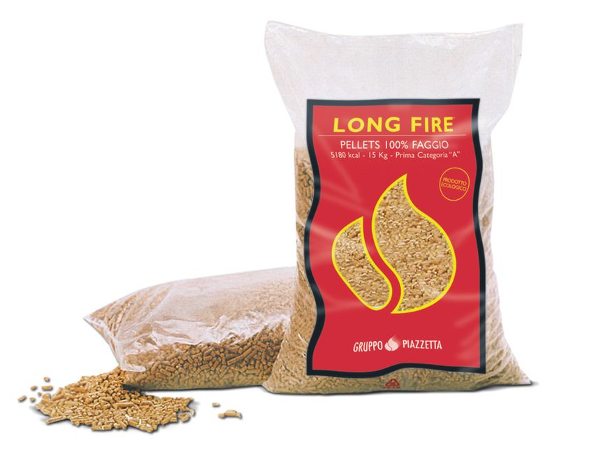
Dear client,
          We thank you for choosing one of our products, the result of technological expertise and continued research in pursuit of a superior
English

          product in terms of safety, reliability and features.
          In this manual you will find all the information and useful advice necessary to get the most out of your appliance in total safety.
                                                                                                                                                                                    DT2010001-00

            IMPORTANT INFORMATION                                                                                                                                                  DT2010208-06

          • This manual has been prepared by the manufacturer and constitutes an integral part            • Ensure that the area where the stove is installed is properly ventilated while the stove
            of the product, and must accompany it throughout its life. In the event of sale or              is lit.
            relocation of the product make sure this booklet accompanies it, since the                    • In the event of technical faults the fuel supply will be interrupted. Restart the stove
            information contained in it is addressed to the purchaser and to anyone involved in             only after having eliminated the cause of the fault.
            the installation, use and maintenance of the product.                                         • The wall where the product is to be placed should not be of wood or any other
          • Read the instructions and the technical information contained in this manual                    flammable material; furthermore it is important to maintain safety distances (refer to
            carefully, before proceeding with installation, use or any repairs.                             section entitled ‘Prevention of domestic fires’ contained in the stove’s manual for use
          • The observance of the instructions and technical information in this manual                     and maintenance).
            guarantees the safety of the user and the product, a more efficient operation and an          • Do not remove the protective grille from the fuel storage tank.
            increased lifespan.                                                                           • Any build-up of unused pellets in the burner left over from repeated failed ignitions
          • The product’s installation and use should conform to the manufacturer’s instructions            must be removed before lighting the stove.
            and to local bylaws.                                                                          • The operation of the stove can cause surfaces, handles, flue system and glass to
          • However, when carrying out any operation we recommend that you follow carefully                 become extremely hot. Touch these parts during operation only with protective
            the instructions contained in this manual, and that you keep it at your disposal.               clothing or other specialised equipment.
          • Installation, electrical connection, checks, maintenance and repairs are operations           • Because of the build-up of heat on the glass, take care that those who are unaware
            which must be carried out exclusively by qualified and authorised personal with                 of the workings of the stove do not delay in the installation area.
            specialised knowledge of the product.                                                         • Keep children informed of safety measures to be followed when the stove is
          • Before installing the product read all instruction booklets relating to installation of the     operational and at other times.
            cladding, the ventilation kit and any other accessories.                                      • Creaking may be heard while the stove is in operation or cooling down. This is not to be
          • Be very careful when moving any ceramic components.                                             considered a defect, but is a consequence of thermal expansion of the component
          • Check that the floor where the product is to be installed is exactly level.                     materials.
          • To help correct potential unevenness and irregularities a sheet of adhesive fibreglass        • The product you have purchased may different slightly from the one illustrated in this
            accompanies the product.                                                                        booklet since the pictures are only given as an indication and not an exact portrayal.
          • Do not block the electrical socket; it should be close to the unit but accessible.
          • Connect the pellet stove to the electricity supply only after it has been connected by              In the event of difficulties or if you are unable to understand the instruction
            an expert to the flue system.                                                                       manual contact your local Piazzetta dealer.
          • The plug at the end of the power supply cable must be easily accessible after                       It is forbidden to place objects which are not heat-resistant on top of the
            installation.                                                                                       stove or within the prescribed minimum safety zone.
          • Use only regulation wood pellets (refer to section entitled “FUEL” ).                               It is forbidden to open the door while the stove is in operation or to operate
          • Never use liquid fuels to light the stove or to relight the embers.                                 the stove when the glass is broken.

          The assembly of the cover should be undertaken by two people (follow the assembly instructions in the attached booklet).
          Plans and diagrams are supplied as examples at the manufacturer’s discretion; in the pursuit of a policy of continuous development and innovation
          the manufacturer may, without prior warning, make any modifications deemed appropriate.
          This document is the property of Gruppo Piazzetta S.p.A.; it may not be divulged in part or in whole to third parties without written permission from
          Gruppo Piazzetta S.p.A. Gruppo Piazzetta S.p.A. reserves all its statutory rights.

            REFERENCE STANDARDS                                                                                                                                                    DT2010209-04

          EN 14785                                                    Residential space heating appliances fired by wood pellets. Requirements and test methods
          EN 832                                                      Thermal performance of buildings - Calculation of energy use for heating - Residential buildings
          UNI 10683                                                   Heat generators fired by wood or other solid biofuels - Installation requirements
          UNI 10847                                                   Single flue systems for liquid and solid fuel generators - Maintenance and inspection - Guidelines
                                                                      and procedures
          UNI 7129                                                    Gas installations for domestic use fired by mains gas supply. Design, installation and maintenance.
          DIN 51731 class HP2                                         Fuels
          ÖNORM M7135                                                 Fuels
          CEI EN 60335-1                                              Safety of household and similar electrical appliances.
                                                                      Safety. Part 1: General requirements
          CEI EN 50165÷1997                                           Electrical equipment of non-electric appliances for household and similar purposes – Safety
                                                                      requirements
          EN 1856-1                                                   Chimneys - Requirements for metal chimneys - Part 1: System chimney products
          EN 1856-2                                                   Chimneys - Requirements for metal chimneys - Part 2: Metal liners and connecting flue pipes
          EN 1443                                                     Chimneys – General requirements

             2             IMPORTANT INFORMATION - REFERENCE STANDARDS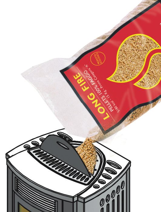
CONTENTS                                                                                                  DT2010187-00

Section       Title                                                             Page           Code

                                                                                       DT2010216-04

                                                                                                                           English
1.0           GENERAL RULES                                                     4
      1.1     Single flueway or chimney                                         5      DT2010024-02
      1.2     Soot inspection                                                   5      DT2010031-00
      1.3     Chimney stack                                                     6      DT2010025-01
      1.4     Fresh air intake                                                  7      DT2010026-00
      1.5     Installation environment                                          8      DT2010215-02
      1.6     Capacity load of the floor                                        8      DT2010032-00
      1.7     Heating capacity                                                  8      DT2010130-01
      1.8     Minimum safety distances                                          9      DT2010536-02
      1.9     Flueway                                                           9      DT2010229-04
      1.10    Connecting to a conventional chimney                              11     DT2010230-02
      1.11    Using an external flue                                            12     DT2010232-02
      1.12    Prevention of domestic fires                                      12     DT2010027-02
2.0           TECHNICAL CHARACTERISTICS AND SPECIFICATIONS                      13     DT2010989-00
      2.1     Features                                                          13     DT2010990-00
      2.2     Technical data                                                    13     DT2010988-00
      2.3     Product identification data                                       14     DT2010041-05
      2.4     Dimensional diagram                                               14     DT2031440-00
      2.5     Wiring diagram                                                    15     DT2030375-02
3.0           FUEL                                                              16     DT2010233-03
4.0           PREPARING FOR INSTALLATION                                        16     DT2010074-06
5.0           INSTALLATION                                                      17     DT2010991-00
      5.1     “Multifuoco” system                                               17     DT2010145-02
      5.2     Electrical connection and the room sensor connection              19     DT2010146-00
      5.3     Installing the external thermostat                                20     DT2010997-00
      5.4     Installing the Y connector (optional)                             20     DT2010148-03
6.0           USE                                                               21     DT2010992-00
      6.1     Loading the pellets                                               21     DT2010730-00
      6.2     Remote control                                                    21     DT2010220-05
      6.3     Lighting for the first time                                       22     DT2010082-03
      6.4     Startup and normal operation                                      22     DT2010221-05
      6.5     Control panel                                                     26     DT2010222-07
      6.6     Setting the language                                              27     DT2010469-03
      6.7     Programming                                                       28     DT2010247-05
      6.8     Timer                                                             29     DT2010242-05
      6.9     Multicomfort                                                      34     DT2010251-03
      6.10    Modifying the transmission unit                                   36     DT2010248-04
      6.11    How the “Multifuoco” system works                                 36     DT2010231-03
      6.12    Safety devices                                                    37     DT2010994-00
      6.13    Opening the door                                                  40     DT2010087-04
      6.14    Humidifier for stove P962                                         41     DT2010993-00
      6.15    Disposal of ashes                                                 41     DT2010049-04
7.0           MAINTENANCE                                                       42     DT2010996-00
      7.1     Cleaning the grate and the grate support                          42     DT2010156-04
      7.2     Cleaning the ash tray                                             42     DT2010100-03
      7.3     Cleaning the firebox                                              42     DT2010324-03
      7.4     Cleaning the smoke chamber                                        43     DT2010159-04
      7.5     Cleaning the flue system                                          43     DT2010092-03
      7.6     Cleaning the ceramic cladding                                     43     DT2010059-03
      7.7     Cleaning the enamelled metal parts                                43     DT2010061-03
      7.8     Cleaning the glass (DAILY)                                        44     DT2010062-04
      7.9     Replacing the window                                              44     DT2010093-05
      7.10    Replacing the remote control battery                              44     DT2010218-03
      7.11    Cleaning the fans                                                 44     DT2010095-06
      7.12    When not in use                                                   44     DT2010096-03
      7.13    Extraordinary maintenance                                         44     DT2010097-03
8.0           TROUBLESHOOTING                                                   45     DT2011179-00
      8.1     Replacing the fuses                                               48     DT2010557-02
              Declaration of conformity Pellet Stove P962                       49     DT2010380-04
              Declaration of conformity Transceiver unit Multicomfort           50     DT2010383-02
              European Regulations                                              51     DT2010382-05

This booklet code H07021560 / DT2000318 Rev. 00 (01/2008) comprises 56 pages.

                                                                                                 CONTENTS           3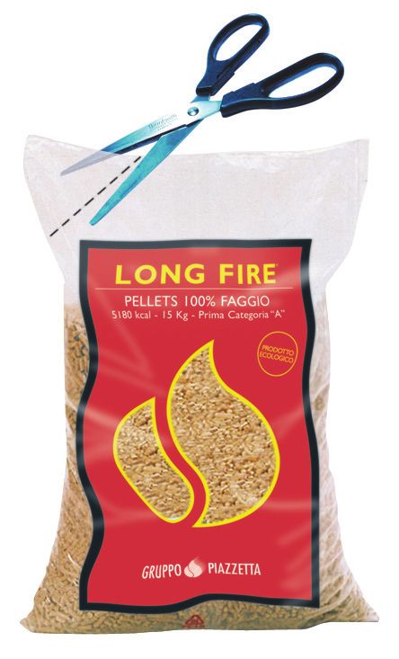
1.0 GENERAL RULES                                                                         DT2010216-04

          Ensure that the installation of your product conforms to all the indications given below.
English

          Fig. 1

                              CHIMNEY STACK

                              SINGLE FLUEWAY
                              OR CHIMNEY

                   CONNECTION TO FLUE

                    SOOT INSPECTION
                    APERTURE

                   FRESH AIR INTAKE

            END ELBOW WITH
            INSPECTION WINDOW

                            MINIMUM SAFETY DISTANCES

                                                        CAPACITY LOAD
                                                        OF THE FLOOR

                                                                                                      DT2030321-00

             4          GENERAL RULES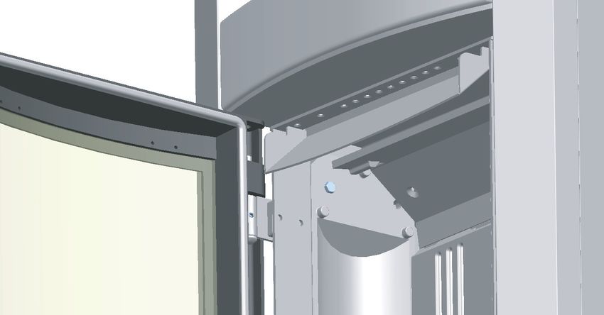
DT2010024-02
  1.1 SINGLE FLUEWAY OR CHIMNEY - Fig. 2 / 6
Every appliance must have a vertical flue pipe operating by natural          Fig. 2

draught to discharge the combustion gases outdoors.

                                                                                                                                                                                                     English
The flue must:
- comply with regulations in force in the place of installation of the
  appliance;

- be tight to the products of combustion, waterproof, suitably insulated,
  made with materials resistant to corrosion by the gases and to stress;
                                                                                                                                MAX 45°                  NO

                                                                                            3,5 m
- be connected to just one stove, fireplace or extraction hood (Fig. 2);                                                                              X

                                                                                     MINIMUM
                                                                                3.5 MMinimo
- be properly sized, with constant free internal section, equal to or
  greater than the diameter of the flue pipe of the stove and at least 3.5
  m in length (Fig. 2);

- be mainly in a vertical position with a deflection from the axis of no
  more than 45° (Fig. 2);

- be at a suitable distance from combustible or flammable materials,
  ensured by an air gap or suitable insulating material;

- be of uniform internal section, preferably round. Square or
  rectangular sections must have rounded corners with a radius of at
  least 20mm and a maximum ratio between the sides of 1.5 (Fig. 3-4-
  5). The walls must be smooth if possible and without narrowing.
  Bends must be regular and without discontinuity (Fig. 6).

                                                                                                                                                                                      DT2030049-00
     It is forbidden to make fixed or mobile apertures on the flue
     pipe to connect appliances other than the one to which it is            Fig. 3                                                                  Fig. 4

     already connected.

     It is forbidden to pass other air ducts or service pipes inside                                                                                                  R
                                                                                                                                                                          (m
     the flue pipe, however large it is.                                                                                   Ø                                                in
                                                                                                                                                                               .2
                                                                                                                                                                                 0)

     If the flue pipe is an incorrect size or installed other than in
     compliance with the above instructions, Gruppo Piazzetta                                                                                                  Accumulo di Creosoto
                                                                                                                                                              Deposit  of Creosote
     S.p.A. cannot be held liable for malfunctioning of the product,                                                                  DT2030050-00                                    DT2030188-00

     damage to property or injury to persons or animals.                     Fig. 5                                                                  Fig. 6
                                                                                                            of di
                                                                                                      Accumulo
                                                                                                    Deposit       Creosoto
                                                                                                               Creosote

                                                                                                                            MAX 45°         NO
                                                                                                      Minimo 3,5 m

                                                                                                                                            X
                                                                                                                           R(
                                                                                                                               mi
                                                                                                                                 n.
                                                                                                                                      20
                                                                                                                                                 P            NO
                                                                                                                                        )

                                                                                                                                      DT2030189-00
                                                                                                                     L (≤ 1,5 x P)
                                                                                                                                                                                      DT2030190-00

                                                                                                                                                                                      DT2010031-00
  1.2 SOOT INSPECTION - Fig. 1

- The flue must have a chamber for collecting solid matter and any condensate located below the connection and which may be easily inspected
  by means of an airtight door. (Fig.1)

- The bends connecting to the flue must have inspection points that allow the system to be checked, cleaned and maintained.
                                                                                                                                                         GENERAL RULES                        5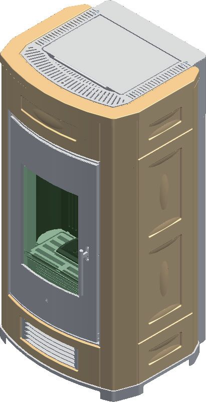
DT2010025-01
1.3 CHIMNEY STACK - Fig. 7 / 11
The chimney stack is a device fitted on the top of the chimney that is designed
to aid dispersion of the products of combustion in the atmosphere. Fig. 7 Fig. 8
English
The chimney stack must comply with the following requirements: B B
- it must have an internal section and shape the same as the flue (A);
B*
- it must have a useful outlet section (B) of not less than twice that of the flue (A);
- the part of the chimney that emerges from the roof or remains in contact with
the outside (e.g. in the case of a flat roof), must be covered with brick or tile
elements and in any case well insulated;
- it must be built in such a way as to prevent the penetration of rain, snow and ** BBequivale al
it is twice
foreign matter into the flue and to ensure that in the event of winds from all doppio
of to di
AA
A A
DT2030051-00 DT2030191-00
directions and angle, discharge of the combustion products is assured
(chimney stack with down-draught cowl).
Fig. 9
Recommended distances for correct chimney operation.
To ensure trouble-free operation of the chimney and allow correct dilution of the
6-8 m
products of combustion in the air, the chimney stack must be installed at the
distances given below:
- 6-8 metres from any buildings or other obstacles that are higher than the
chimney stack;
- 50 centimetres higher than any obstacles located at a distance less than 5
metres;
- outside the reflux area. The size and shape of this area differ according to the
angle of inclination of the roof and it is therefore necessary to adopt the
DT2030052-00
minimum heights shown below.
Example: Check the slope of the roof (column α), and the anticipated distance
of the chimney stack from the axis of the ridge (column A); if the distance is
greater than “A” the height of the chimney stack may be read in (column H); if
the distance is less than “A” the chimney stack must rise above the ridge by 0.5
metres.
Fig. 10
0.50
0.50mm FLAT
TETTOROOF
TETTO PIANO
PIANO
0.50
0.50mm
pari5oominore
pari mminore over 5 m
maggiore
maggiore 55mm pari5oominore
pari mminore
or55less
mm or55less
mm
DT2030053-00
Fig. 11
distanza
distancemaggiore
distanza maggiore
more than AA A SLOPING
TETTO
TETTO ROOF
INCLINATO
INCLINATO
distance
distanza
distanza
min. uguale
ugualeAAA
at least
min. 0.50
0.50 above
0.50m oltrethe
moltre ridge
ililcolmo
colmo
REFLUX AREA
HHmin.
min. height
altezza of
altezzazona
zonadidi
ridgecolmo
asse
asse axis
colmo reflux
reflussoZZ Z
reflussoarea
αα
DT2030192-00
Horizontal width of reflux Minimum height of Height of reflux
Pitch of the roof
area from ridge axis outlet from roof area
α A H min Z
15° 1,85 m 1,00 m 0,50 m
30° 1,50 m 1,30 m 0,80 m
45° 1,30 m 2,00 m 1,50 m
60° 1,20 m 2,60 m 2,10 m
6 GENERAL RULES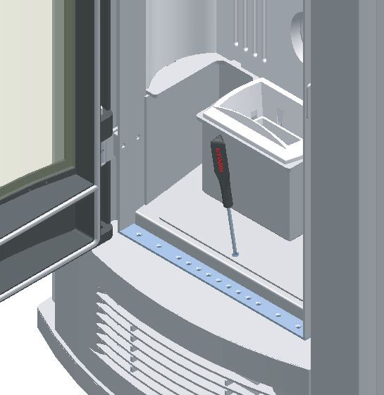
DT2010026-00
  1.4 FRESH AIR INTAKE - Fig. 12 / 15
The stove/fireplace must have the necessary air available to ensure          Fig. 12                  Fig. 13

proper combustion.

                                                                                                                                        English
- Make sure that the room in which the stove/fireplace is to be installed
  has an air intake of at least the size indicated in the paragraph
  “TECHNICAL DATA”.
- The fresh air intake may be protected by an external grille provided it
  does not reduce the minimum section of the recommended airflow
  and is in a position whereby it cannot be obstructed.

                                                                                       DT2030054-00                      DT2030193-00
The air necessary for the fire may be obtained in different ways:
- Figure 12 through an external grille direct to the room of installation;
                                                                             Fig. 14
- Figure 13 with ducting through pipes direct to the room of
  installation, increasing the recommended minimum free cross
  section by at least 15%;
- Figure 14 through a communicating hole from an adjacent room to
  the place of installation: this system may only be used if the air flows
  freely from the outside through fixed apertures;
- Figure 15 from an adjacent room to the place of installation, but only
  if the air flows freely through apertures communicating with the
  outside.

                                                                                                                         DT2030194-00

                                                                             Fig. 15

                                                                                                                         DT2030195-00

                                                                                                         GENERAL RULES           7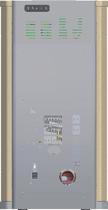
DT2010215-02
            1.5 INSTALLATION ENVIRONMENT
          The appliance must be installed in a location which allows safe and convenient use as well as easy maintenance. If the product being installed
          requires an electrical socket, the room must also be provided with an earthed power supply in accordance with current regulations.
English

                Do not install a wood-burning appliance in a bedroom, bath or shower room or in any room where another heating system not
                equipped with its own air supply (fireplace, stove etc.) has already been installed.

          The room or rooms adjacent to that where the appliance is to be installed must conform to the following requirements:

                it must not be used as a car bay, a store for combustible material, nor for any activity which carries a risk of fire;

                there must be no vacuum relative to normal atmospheric pressure as a result of the contrary draught created by a prior installation of an
                open fire or of an extractor system;

                do not install two stoves, a stove and a fireplace or a stove and a wood-burning range etc. in the same location since the draught of one
                device can interfere with the draught of another;

          - the use of equipment adapted for cooking food with non-extractor hoods is permissible only in rooms to be used as kitchens;
          - equipment using gas type C is permitted (refer to regulations in force in the place of installation);

                equipment using gas type B is not permitted (refer to regulations in force in the place of installation);

                using the stove or fireplace simultaneously with shared ventilation systems is not permitted, whether with or without extractor fans.
                Similarly the use of other devices or equipment, such as air-conditioning systems or other heating systems which use fans to circulate
                air, is not permitted. These devices can cause a pressure drop in the environment of installation even if they are installed in adjacent,
                communicating rooms.

                                                                                                                                                      DT2010032-00
            1.6 CAPACITY LOAD OF THE FLOOR

          Check the load-bearing capacity of the floor, referring to the weight of the product given in the paragraph “TECHNICAL DATA”.
          If the floor does not have a suitable load-bearing capacity, adequate countermeasures must be taken, for example, by using a sheet metal plate to
          distribute the load.

                                                                                                                                                      DT2010130-01
            1.7 HEATING CAPACITY
          Check the heating capacity of the appliance by comparing the rated power given in the paragraph “TECHNICAL DATA” with the power required by the
          environment to be heated.
          The energy requirement may be calculated approximately by multiplying the square metres of area by the height of the ceiling; the result is then
          multiplied by a coefficient, which depends on the degree of insulation of the building, that is, on internal and external factors of the dwelling:
          a) Internal factors: type of window and door frames, thickness of the insulation and walls, type of building materials, presence of stairwells, walls with
              extensive glazing, high ceilings, position of the rooms to be heated in relation to other adjacent heated or unheated rooms, …
          b) External factors: geographical position, average outdoor temperature, exposure, wind speed, latitude, altitude, …
          Example of approximate calculation of the energy requirement to heat a fixed volume to 18/20° C:
          The coefficient that is normally used is determined according to the real conditions as they occur case by case.
          - From 0.04 to 0.05 kW per cubic metre in a well insulated environment
          - From 0.05 to 0.06 kW per cubic metre in a poorly insulated environment.
          3 rooms measuring 20 m2 X (H ceiling) 2.7 m = 162 m3 (volume)
          In an environment with a good degree of insulation, an average value (coefficient) of 0.045 kW may be taken
          162 (volume) X 0.045 (kW) = 7.3 kW necessary (6300 kcal/h)
          Conversion 1kW = 860 kcal/h

                Consult a heating technician or engineer for a correct check and calculation of the requirement of the environments to be heated (see
                “REFERENCE STANDARDS”).

                Rated power being equal, products with the Multi-fire system can evenly distribute heat throughout the rooms to be heated.

            8           GENERAL RULES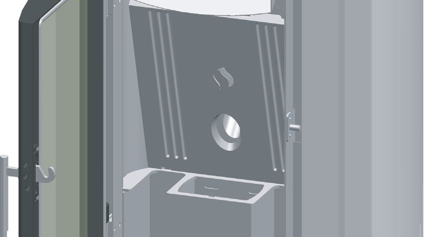
DT2010536-02
 1.8 MINIMUM SAFETY DISTANCES - Fig. 16 / 18

First of all decide the exact position for installation of the stove.     Fig. 16

                                                                                                                                                                            English
Check the minimum safe distances from heat sensitive or inflammable
                                                                                                             Parete posteriore
                                                                                                                 Rear wall
materials, from load bearing and other walls and also from wooden
elements, furniture, etc.                                                                                              A

                                                                                                                                                                 laterale
                                                                                Sidelaterale
In the case of flooring that is heat sensitive or inflammable the floor

                                                                                     wall

                                                                                                                                                           Side wall
should be protected with non-combustible insulating material, e.g.

                                                                                                                                                          Parete
                                                                              Parete
                                                                                                                   STUFA
sheets of steel plate, marble, tiles, etc.
                                                                                               B                    STOVE                 B
The minimum distances are:
 A    20 cm from the wall behind the stove
 B    20 cm from the side wall
 C    80 cm in the heat radiation area and from the hot air fan
                                                                                                   E                                 E
 D    50 cm floor proection                                                                                        D       C
 E    30 cm (measured from the internal corner of the door opening)                                    Protezione pavimento
                                                                                                         Floor protection

Connection to the flue must respect the 40 cm minimum safety
                                                                                                   Zona radiante
                                                                                                      Heat       dell’apertura
                                                                                                           radiation   area
distance from heat-sensitive structural components or inflammable                                         del focolare

                                                                                                                                               DT2031515-00
materials (wood panelling, beams or ceilings, etc).

     Keep away from the stove any combustible product such as             Fig. 17                                          Fig. 18
     wooden furniture, curtains, carpets, combustible liquids, etc.
     when it is lit /working (minimum distance 80 cm).

     It is advisable to leave more than the indicated 20 cm free at
     the side of the stove to facilitate any maintenance on the
     appliance.

                                                                                                                                                  MIN 40 cm
                                                                                                       MIN 40 cm

                                                                                                   DT2030335-00                                DT2030336-00

                                                                                                                                               DT2010229-04
 1.9 FLUEWAY - Fig. 19 - 20

     The pellet stove is not the same as other stoves. It has a forced draught of flue gas by a fan, which keeps the firebox in a vacuum and the
     entire flueway slightly pressurised. For this reason the flue must be completely airtight and correctly installed to ensure both trouble-free
     operation and user safety.

- The flueway must be made by specialised personnel or firms, as outlined below.
- The flue must be installed in such a way as to guarantee that periodic cleaning can be carried out without dismantling any parts whatsoever.
- Pipes should always be sealed with silicone (not cement-based sealants) or specially adapted gaskets/seals, which retain their strength and
  elasticity at high temperatures (250°C), and should be fixed with 3.9 mm ø self-tapping screws.

     Do not install dampers or valves that could block the passage of flue gas.

     Do not connect to a flueway into which other appliances (boilers, extractor hoods, etc.) discharge fumes or vapours.

                                                                                                                               GENERAL RULES                           9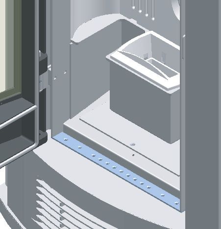
Fig. 19
          Pipes and maximum usable lengths
English

                                                                                                                                                         RACCORDO
                                                                                                                                                       Straight   reducer
          Pipes of painted aluminium-clad steel (minimum thickness 1.5 mm),                                                                            ø ø8080> >
                                                                                                                                                                øø  100
                                                                                                                                                                  100
          stainless steel (AISI 316) or enamelled steel (minimum thickness 0.5
          mm) with a nominal diameter of 80 or 100 mm (for pipes which run                                                    ø 100mm
          inside the flue maximum diameter 150 mm) can be used.
          The male-female connectors must have a minimum length of 50 mm.
          The diameter of the pipes depends on the type of installation. The stove
          was designed to take 80 mm diameter pipes but, as shown in Table 1,
          in some cases the use of double-lined 100 mm diameter pipes is                                                                                      ø 80mm
          recommended.

                                         TABLE 1 – LENGHT PIPES
                                                                  WITH 80mm Ø PIPE WITH100mm
                                                                                        DOUBLE-WALLED
           TYPE OF INSTALLATION                                                               Ø PIPE
           Maximum length (with three 90° bends)                        4.5 m              8m
           For installations more than 1200m above sea level              -              Required
           Maximum number of bends                                        3                 4
           Length of horizontal sections with minimum 3% gradient        2m                2m
                                                                                                                                               RACCORDO A T CON TAPPO
                                                                                                                                                  Tee with sealing
                                                                                                                                               A CHIUSURA          plug
                                                                                                                                                            ERMETICA

                  Losses in pressure associated with a 90° bend can be
                  compared to those incurred by one metre of pipe. An
                  inspectable union-tee can be considered equivalent to a 90°                                                                                      DT2030337-00

                  bend.
                                                                                                        Fig. 20

          EXAMPLE: : if installing a section greater than 4.5 m in length with 80                                                      Insulating material
                                                                                                                                       ISOLANTE
          mm diameter pipe, calculate the maximum usable length in the
          following ways:

                                                                                                                                 Tee
                                                                                                                                 RACCORDO    AT
          - If a maximum of three 90° bends are used, the maximum length of
            the section will be 4.5 m                                                                         Tee
                                                                                                              RACCORDO   AT                             2m
          - If a maximum of two 90° bends are used and bearing in mind that a                                                                     Max . 3%)
                                                                                                                                                  (mi n
            90° bend can be replaced by one metre of pipe, the maximum length                                     Direction
                                                                                                                   DIREZIONEof
            of the section will be 4.5 m+1 m=5.5 m                                                                 DI PULIZIA
                                                                                                                  cleaning

          - If a maximum of one 90° bend is used and bearing in mind that a 90°                                                                      DIREZIONE  DI cleaning
                                                                                                                                                      Direction of PULIZIA
            bend can be replaced by one metre of pipe, the maximum length of
            the section will be 4.5 m+1 m+1 m=6.5 m

          Where 100 mm diameter pipe must be used, connect it to the stove flue
          outlet with a 80 mm union-tee then use a 80 mm 100 mm adaptor (not
          supplied by Piazzetta) (Fig. 19).                                                                                      DIREZIONE
                                                                                                                                 Direction ofDIcleaning
                                                                                                                                                PULIZIA
                                                                                                                                                                   DT2030338-00

          Union-tee
          The use of this type of fitting must allow for the collection of condensate
          mixed with soot, which builds up inside the pipe. It must also permit
          periodic cleaning of the flue without the need to disassemble the pipes.
          This type of fitting can be bought at Piazzetta retail outlets together with
          the pipes.
          An example is given below of a flueway connection, which allows
          complete cleaning without having to disassemble the pipes (Fig 20).

             10           GENERAL RULES
DT2010230-02
1.10 CONNECTING TO A CONVENTIONAL CHIMNEY - Fig. 21 - 22
If you wish to use an existing chimney it is strongly recommended that Fig. 21
English
you have it checked by a professional chimneysweep to ensure that it
is completely airtight. The reason for this is that the smoke, because it Chimney stack
COMIGNOLO
is slightly pressurised, can infiltrate any cracks in the flue and escape
into living spaces. If upon inspection you find that the chimney is not
completely sound, it is recommended that you insert piping made of
new material. If the existing chimney is wide enough we recommend a
Tee
RACCORDO A T
pipe with a maximum diameter of 150 mm. It is also recommended that
you insulate the chimney flue (Fig. 21-22).
Pipes and bends made by Gruppo Piazzetta S.p.A. are recommended
for connection to the flueway, since they are sized to fit the flue outlet
of the appliance.
CON CANNA
With FUMARIA
damaged flue
Other pipes may be applied after adaptation and checking of the NON INTEGRA
compatibility of the coupling, taking into account that the pipes and INSERIMENTO DI
Pipe insertion
UN TUBO
bends must be made in compliance with current regulations. In this
case, however, Gruppo Piazzetta S.p.A. only guarantees trouble-free
operation for parts that it manufactures and that are used according to
specifications. ø 80 mm Max ø150 mm
Connection to the flue must respect the 40 cm minimum safety
distance from heat-sensitive structural components or inflammable
materials (wood panelling, beams or ceilings, etc). (See figures 17-18).
Inspection
SPORTELLI PER
windows
ISPEZIONE
- If the connector has to pass through partitions or walls of inflammable
Insulating
ISOLANTE material
DT2030339-00
or heat-sensitive materials, or through load-bearing walls, create:
an insulating barrier equal to or greater than 10 cm around the
connector using mineral-based insulating material (rock wool, Fig. 22
ceramic fibre) with a nominal density greater than 80 kg/m3. Closing
FLANGIAflange
DI CHIUSURA
- If the connector has to pass through non-flammable partitions or
walls, create:
an insulating barrier equal to or greater than 5 cm around the
connector using mineral-based insulating material (rock wool,
ceramic fibre) with a nominal density greater than 80 kg/m3.
- Check that the connection to the flueway is gas/smoke-tight, since
the appliance operates in a vacuum.
- Check that the pipe does not penetrate too far into the flueway,
thereby choking the pipe for the passage of smoke and combustion Sealing
FLANGIA flange in stainless
DI CHIUSURA ERMETICA
gases. steel or aluminium
IN ACCIAIO INOX O ALLUMINATO
Ensure that all installation work is carried out to professional
standards.
Fresh airPRESA
intake with ESTERNA
D'ARIA
non-closable grilleRICHIUDIBILE
CON GRIGLIA NON
DT2030340-00
GENERAL RULES 11DT2010232-02
1.11 USING AN EXTERNAL FLUE - Fig. 23
Fig. 23
An external flue can be used provided it complies with the following
English
requirements:
- use only insulated stainless steel pipes (double-lined) fixed to the d
outside wall of the building (Fig. 23);
- there must be an inspection opening at the base of the flue to permit
periodic checks and maintenance;
- the flue must be fitted at the top with a chimney stack with down-
draught cowl, also ensuring compliance with the safety distance from
the roof ridge as outlined in the section entitled “GENERAL RULES”,
under “CHIMNEY STACK”.
Ensure that all installation work is carried out to professional
standards.
FreshD'ARIA
PRESA air intake with CON
ESTERNA
non-closable
GRIGLIA grille
NON RICHIUDIBILE
DT2030341-00
DT2010027-02
1.12 PREVENTION OF DOMESTIC FIRES
The product must be installed and used in compliance with the
manufacturer’s instructions and European and national standards as
well as local regulations.
When a flue pipe passes through a wall or a ceiling, special
installation methods must be applied (protection, thermal
insulation, distances from heat-sensitive materials, etc.) See
the paragraph “Connection to the flueway
- It is also recommended that all elements made of combustible or
inflammable material, such as beams, wooden furniture, curtaining,
flammable liquids, etc. be kept outside the heat radiation range of the
stove and in any case at a distance of at least 80 cm from the heating
block.
- For other information, see the paragraph “MINIMUM SAFETY
DISTANCES” and “CONNECTION TO A CONVENTIONAL CHIMNEY”.
- The flue pipe, chimney stack, chimney and fresh air intake must
always be free of obstructions, clean and checked periodically, that is,
at least twice during the seasonal period from the lighting of the stove
and during its use. When the stove has not been used for some time
it is advisable to carry out the checks mentioned above. For further
information, consult a chimneysweep.
- Only use recommended fuels (See paragraph “FUEL”).
12 GENERAL RULES2.0 TECHNICAL CHARACTERISTICS AND SPECIFICATIONS DT2010989-00
DT2010990-00
2.1 FEATURES
English
Cladding: hand-made majolica
Interior: steel
Baffle plate and hearth: cast iron
Grate: cast iron
Door: cast iron with ceramic glass heat resistant up to 750°C
Handle: in steel with nickel-plated finish
Control panel: remote control with LCD and digital control panel on stove
Timer thermostat: standard with daily, weekly and weekend programming modes divided into two time bands
Power setting: from 1 to 5
Ash drawer: removable
Fuel: natural pure wood pellets (see section “FUEL”)
Heating: forced ventilation with the Multifuoco System with two fans and possibility of separate operation, four fan
settings, possibility of operation with room temperature setting as measured by the remote control (see
section “MULTICOMFORT”), front hot air outlet at bottom with two baffles to separate flow, two outlets at
rear for ducting if required (see section “MULTIFUOCO SYSTEM”)
Humidifier: stainless steel, contains 100 cl water
DT2010988-00
2.2 TECHNICAL DATA
UNIT P962
Nominal thermal power (max/min) kW 12 / 3.5
Hourly fuel consumption (max/min) kg/h 2.68 / 0.85
Efficiency % > 85
Draught when connected to chimney Pa 10÷15
Fuel tank capacity kg / (l) 32 / (49)
Electrical power supply V 230
Frequency Hz 50
Frequency only for Japan Hz 60
Maximum power rating W 350
Power rating (max/min) W 170 / 130
Exhaust outlet diameter cm ø8
Fresh air intake (recommended minimum section) cm2 100
Weight of stove with majolica kg 203
Packing sizes (DxWxH) cm 69x69x130
Data obtained under laboratory conditions with pellets of heat production rated at 5kWh/kg
N.B.: the above data may vary according to the characteristics of the pellets being used. (See section “FUEL”)
TECHNICAL CHARACTERISTICS AND SPECIFICATIONS 13DT2010041-05
2.3 PRODUCT IDENTIFICATION DATA
The rating plate gives the data and ratings of the appliance.
English
If the rating plate is missing, has been removed or tampered with,
any installation and maintenance operations are made difficult due
to lack of product identification.
In the event of damage, please ask the Piazzetta after-sales service
centre for a copy. Production identification
TARGHETTAandTECNICA
rating plate
DI IDENTIFICAZIONE
DEL PRODOTTO
Product name
Serial number
DT2031673-00
DT2030624-02
DT2031440-00
2.4 DIMENSIONAL DIAGRAM
117,3
DATI DI IDENTIFICAZIONE P962
DT2031673
33
8,5 18
4,5
7,7 Scarico
Diameterø8
Ø8
28
55
61
Dimensions in cm
DT2031440-00
14 TECHNICAL CHARACTERISTICS AND SPECIFICATIONSDT2030375-02
2.5 WIRING DIAGRAM
English
A B
C C
V
U
SPEED2
SPEED1
1 1
N
L
PE
T 1 1
PE FAN1
2 2
FAN2
E D
5
3
4 5 S 2
4
3 1
1
5 4 2
I
F F 3
N
FUMI
FAN1 FAN2
SCAM.
5
G
COC.
ACC.
DISPLAY
AL2
AL1
N
SERIALE
R
3
N.AMB.
N.PEL.
N.H2O
TERM.
-TC1+
GND
ENC
BLU
+5V
Q
3 7 7
3 5
2 4 5 M
H
P
3
6 6
O
L
N
DT2030375-05
SCHEMA ELETTRICO P961
Pos. Key to parts DT2030375 Pos. Key to parts N° Key to colours
A Emergency display M Power supply with fuse (5X20 4AH250V) 1 White
B Antenna N Smoke sensor 2 Yellow-green
C Room fan O Room sensor 3 Black
D Pellet-loading auger P External thermostat connection 4 Brown
E Flue gas fan Q Serial port DB9 5 Blue
F Capacitor R Motherboard 6 Red
G N.O. Pressure switch (normally open) S Fuse 5X20 4AL250V 7 Grey
H N.C. 80° thermostat (normally closed) T Fan card
I Microswitch U Fuse 5X20 500mAL250V
L Ignition glow plug V Flat cable
TECHNICAL CHARACTERISTICS AND SPECIFICATIONS 153.0 FUEL DT2010233-03
The wood pellet is obtained by pressing wood sawdust left over from the - reduces efficiency
English
working of natural dried wood. The typical small, cylindrical form is obtained - means that proper stove operation cannot be guaranteed
by passing the material through a die. Thanks to lignin, a natural element - causes dirt to build up on the glass
which is released during the pressing of the raw material, the pellets acquire - leaves particles which have failed to burn and heavy cinders
a good consistency and compactness without requiring treatment with
additives or caking agents. The presence of moisture in the pellets increases their volume and
There are various types of pellet on the market with qualities and causes them to split which in turn causes:
characteristics that vary depending on the processes they have undergone - malfunction of the fuel-loading system
and the type of wood used in their production. - inefficient combustion
Since the characteristics and quality of the pellet considerably affect
stove performance, efficiency and proper operation, we recommend that Pellets should be stored in a sheltered, dry place.
you use high-quality pellets.
Gruppo Piazzetta S.p.A has tested and programmed its stoves and can To use good quality pellets with dimensions and heat-producing properties
ensure best performance and trouble-free operation using pellets with other than those recommended above, it will be necessary to change the
the following specific characteristics: stove operating parameters.
Pellet characteristics
This “customisation” of stove settings must be carried out at a Gruppo
Components natural pure wood pellet
Length, approx. 10 – 30 mm Piazzetta S.p.A. Service Centre or by specially qualified personnel
Diameter, approx. 6 – 6.5 mm authorised by Gruppo Piazzetta S.p.A.
Apparent density, approx. 650 kg/m3
Specific weight, approx. > 1.0 kg/dm3 Using pellets that are out of date or not in conformity with the
Net heat value, approx. 5 kWh/kg manufacturer’s recommendations not only damages the stove and
Moisture content, approx. < 8%
jeopardises its performance, but can render the guarantee null and
Residual ash, approx. < 0.34%
N.B. the above data refer to beech/fir wood pellets void and relieves the manufacturer of all liability.
To ensure trouble-free operation:
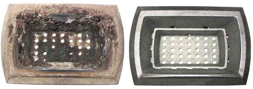
Fig. 24
DO NOT use pellets with dimensions other than those recommended by the
manufacturer
DO NOT use pellets which are out of date or which contain loose sawdust,
resins, chemical substances, additives or caking agents.
DO NOT use damp pellets.
Choosing other and unsuitable pellets:
- obstructs the grate and flue gas pipes
- increases fuel consumption DT2030346-00
4.0 PREPARING FOR INSTALLATION DT2010074-06
During operation some parts of the stove (door, handle, controls, ceramic • use slow continuous movements when moving the pack to avoid
parts) can reach high temperatures. Take great care and all the necessary jerking the ropes, chains, etc.;
precautions, especially in the presence of children, the elderly or disabled • do not tilt the package excessively to avoid toppling;
and pets. • never stand in the vicinity of loading/unloading equipment (forklift
To prevent accidents or damage to the product we recommend the trucks, cranes etc).
following:
• unpacking and installation must be carried out by at least two people; Before installing the product make sure that you have the
• every operation involving movement of the product must be carried correct equipment.
out with the proper tools in full compliance with current safety Unpack the product being careful not to damage or scratch it,
regulations; take the accessories pack and any pieces of polystyrene or
• the packaged product must be kept in the position according to the cardboard used to wedge moveable parts etc. out of the stove
directions shown by the diagrams and notices on the pack; firebox.
• if ropes, straps or chains are used, ensure that they are able to take Keep packaging (plastic bags, polystyrene, etc.) out of reach
the weight of the pack and that they are in good condition; of children, since it could be a potential source of danger, and
dispose of according to local regulations.
16 FUEL - PREPARING FOR INSTALLATION5.0 INSTALLATION DT2010991-00
Pursuant to current regulations on the safety of electrical equipment, you must contact a Piazzetta After-Sales Service Centre or a qualified
English
electrician for all and any work connected with installation, maintenance or servicing that involves access to electrical parts.
External pressure switch Cladding
• The stove is fitted with an external pipe tap for measuring the • Having completed assembly of the stove and installed any external
pressure (vacuum) in the flue gas outlet pipe. Authorised personnel room thermostat, proceed with assembly of the stove cladding,
should carry out this verification and control whilst the stove is being referring to the ceramic cladding instruction booklet provided with the
DT2010071-01
installed. stove.
DT2010145-02
5.1 MULTIFUOCO SYSTEM - Fig. 25 / 27
• Piazzetta’s technological research and development mean that Fig. 26
this pellet stove offers the advantages of the ‘Multifuoco’ system,
a system exclusive to and patented by Gruppo Piazzetta S.p.A., a
true innovation in the field of pellet stoves.
• The ‘Multifuoco’ system revolutionises all methods of heat
circulation currently in use in pellet stoves: the heat produced by
the furnace is circulated into the atmosphere not only from the
base of the stove itself, it can also be directed via 75mm-diameter
flexible pipes to adjoining rooms (fig 26).
This exclusive heat distribution system offers many notable
advantages: even spread of temperatures; heating adjoining
rooms.
The heat produced is propelled by a fan and distributed via the
DT2030162-00
outlet at the back of the stove.
Fig. 27
• The front grill is equipped with two deflectors (fig 27) to change
the direction of the heat current as it exits the front of the stove.
To deflect the heat current in the desired direction simply adjust
the angle of the deflectors (fig 30) using the lever provided (fig
29).
When the stove is lit, use the glove provided to carry out
this operation.
Fig. 25
DT2030213-00
DT2030163-00
INSTALLATION 17Fig. 28 Fig. 29
Instructions for redirecting heat
English
• The fan system which expels heat into the atmosphere is
equipped with two Y-shaped devices which effectively allow the
air flow to be doubled up, directing it via a flexible pipe to the
back of the stove from where it can then be directed into
adjoining rooms.
deflectors DT2030221-01 DT2030222-01
• Below are some examples of possible installations and examples
of how to redirect the hot air in order to heat other rooms. Such
Fig. 30
examples are intended as demonstrations; optimum performance
depends in each case on conditions in the room where the stove
is installed and in the adjoining rooms.
it is of fundamental importance that when redirecting heat
from the rear of the stove the outlets and the Y-connector
DT2030223-01
are free of blockages to avoid overheating. In cases where
one rear outlet from the fan is to be employed, the outlet
Fig. 31
must always be kept open.
• The examples give guidelines for redirection. Each diagram
represents only one solution of the many possible.
SOLUTION 1 - Fig. 31 - 32:
• the stove is installed in the room which is to be heated, with the heat
directed to the front only, as when the stove arrives from the factory
(fig 31). Alternatively the air can flow to the rear by connecting a 7.5
cm-diameter flexible pipe to the fan (fig 32). In this scenario the
DT2030216-00
stove heats the room where it is installed by radiation only, and
heats the adjoining room by means of redirection to the rear.
Fig. 32
For the example shown in fig 32 it is necessary to use an
outlet which is permanently open. Non-closable vents
SOLUTION 2 - Fig.33:
• The stove is installed in the room to be heated with the heat
directed to the front by one fan. A second fan directs to the rear
allowing the heating of a second room. A 7.5 cm-diameter flexible
1m
pipe with a maximum length of 6 metres is connected to the fan’s
outlet (fig 33).
DT2030217-00
For the example shown in fig 33 the vent should be permanently
Fig. 33
open.
Non-closable vents
6m
DT2030218-00
18 INSTALLATIONFig. 34
SOLUTION 3 - Fig. 34:
English
• The stove is installed in the room to be heated with the heat
channelled in three directions. One fan propels heat to both front
and rear of the stove via the Ydevice and a length of flexible pipe
of diameter 7.5 cm. The output of the second fan is directed to
the rear only via a flexible pipe of diameter 7.5 cm and maximum non-closable vent
6m
length 6 metres (fig 34).
For the example shown in fig 34 the vent at the end of the
single redirection should be permanently open.
1m
DT2030219-00
SOLUTION 4 - Fig. 35:
• Extending the previous solution, with the stove installed in the
Fig. 35
room to be heated and the heat directed as in SOLUTION 3, with
the outlet from one fan doubled using a second Y connector at
the rear as shown. Use 7.5 cm-diameter flexible pipe with a
maximum total length of 6 meters (fig 35).
5m
open vent
For the example shown in fig 35, for the redirection to
function correctly and to avoid overheating, it is necessary
to use non-closable vents as shown. During operation the
vent closest to the stove should be partially open but never partially open vent 1m
closed to avoid overheating. 0,5 m
0,5 m
DT2030220-00
Ducting through walls or floors - Fig. 36 / 39
Fig. 36 Fig. 37
To ensure efficient ducted heat distribution:
1) lag the pipe with insulating material to limit heat loss and
ensure a sufficiently high air temperature;
2) do not exceed the total maximum hose length of 4.5 m.
Below are some examples of how the hose can be installed in walls
or floors (for better performance, lag the hose with suitable
DT2030168-00 DT2030169-00
insulating material).
Fig. 38 Fig. 39
DT2030170-00 DT2030171-00
Fig. 40
hot air outlet vent
Hot air outlet vent radiation area (mm) - Fig. 40
A safety area must be ensured around the hot air outlet vent within
which there must be no flammable objects (furniture, carpets,
curtains, etc.) or heat sensitive materials (wood, plastic, etc.).
R6
00
600
The diagram to the side shows the measurements for this safety
area, which includes 600 mm from the upper edge of the vent.
DT2030172-00
600 600
INSTALLATION 19DT2010146-00
5.2 ELECTRICAL CONNECTION AND THE ROOM SENSOR
CONNECTION - Fig. 41 / 43
• The stove comes with a power cable which must be connected to Fig. 41
English
a 230v/50Hz (230V/60Hz only for Japan) supply. Connection to 1
the rear of the stove is shown in fig. 41. 2
• The power rating is indicated in the paragraph “TECHNICAL
DATA” in this booklet.
3
• According to law the installation must be earthed and include a
4
residual current circuit breaker.
• Ensure that in its normal position the power cable does not come
into contact with any heated parts. DT2031443-00
1 External socket for connection of room sensor.
2 Socket for power lead.
3 External pressure pipe tap.
Ensure that the electrical socket is accessible also after
4 Hole for inserting cable gland PG7 for connection of external thermostat.
installation of the stove. 5 Room sensor connection.
6 Power cable connection.
• When installing the stove, it is necessary to connect the room Fig. 42 Fig. 43
sensor (provided) in the correct socket (fig. 42). The sensor can
be positioned as shown in fig. 42, otherwise remove the band and
5
uncoil the lead and then place the sensor in a spot where a more 6
accurate room temperature reading can be obtained.
COLLEGAMENTO ELETTRICO P962
DT2031443
DT2031444-00 DT2031445-00
DT2010997-00
5.3 INSTALLING THE EXTERNAL THERMOSTAT - Fig. 41 - 44 / 46
• The appliance is designed for connection to an external room Fig. 44
thermostat. To connect the thermostat use a 2x0.5 mm2 cable secured 1
with a PG7 cable gland to be inserted in the relative hole in the rear panel
4
(fig. 41). Only authorised personnel should carry out this operation.
2 3
DT2030076-00
Installation can be carried out with any type of room thermostat
COLLEGAMENTO SONDA AMBIENTE P962
COLLEGAMENTO CAVO DI ALIMENTAZIONE P962
but requires a PG7 cable gland similar to that shownDT2031444
in fig. 44. To DT2031445
1 Thermostat. 3 Cable clamp.
connect the room thermostat to the electronic board, refer to the 2 Electronic board 2-pin terminal. 4 Thermostat cable terminal.
wiring diagram. Fig. 45
Proceed as follows for installation:
• Remove the protective panel from the electronic board and then remove the
rear panel (fig. 45).
• Insert the thermostat cable through the PG7 gland and then insert the gland
in the hole in the rear panel (fig. 46).
1
• Connect the room thermostat cable terminal to the 2-pin terminal of the
electronic board (fig. 45). DT2031446-00
• Refit the rear panel, ensuring that the cable inside the stove cannot come
Fig. 46
into contact with hot or moving parts.
• Refit the protective panel over the electronic board.
1
DT2031447-00
20 INSTALLATIONDT2010148-03
5.4 INSTALLING THE Y CONNECTOR (OPTIONAL) - Fig. 47 / 55
Fig. 47 Fig. 48
• The redirection of heat to adjoining rooms is at the user’s left fan
English
discretion.
• The Y-connector can be attached to either fan.
• You can choose to use only one of the fans’ outlets to heat
adjoing rooms, in which case it is more convenient to use the right fan
right fan. Proceed as follows:
DT2030229-00 DT2030230-00
For convenience, the following assembly operations should
Fig. 49
be carried out during the installation phase first on the left fan
(as viewed from the rear) and then on the right fan (fig 47).
1. Take off the stove’s back panel
2. Uncoil the flexible pipe from the fan’s outlet by unscrewing the
clip which holds it in place.
3. Cut around 5cm of flexible pipe (fig 48).
4. Fix the flexible pipe to the Y-connector using the clip provided
DT2030175-00
(fig 49).
5. Fix the Y-connector to the fan’s outlet using the screws Fig. 50 Fig. 51
provided (fig 50). (for the left fan see fig 52)
6. Attach the second flexible pipe to the Y connector using the clip
provided (fig 51).
7. Repeat stages 2 - 6 for the right fan.
8. Take off the sub-section of the back panel (fig 54).
9. Replace the back panel.
10. Move the stove closer to the wall (fig 53) and, using the clips
provided, fix the two flexible pipes to the pipes in the wall (fig DT2030232-00 DT2030178-00
55).
Fig. 52 Fig. 53
11. Place the stove in the desired location, respecting the minimum
safety distances (see section 1.8). tightening screws
DT2030231-00 DT2030180-00
Fig. 54 Fig. 55
DT2030233-00 DT2030181-00
INSTALLATION 216.0 USE DT2010992-00
• Do not use the stove as a cooking appliance.
• Ensure that the room in which the stove is installed is sufficiently well ventilated (fresh air intake).
English
• Ensure that all joints in the flue are hermetically sealed using a silicone- (not cement-) based sealant which is resistant to temperatures of up
to 250ºC and which shows no sign of deterioration.
• Check (or have checked) regularly that the flue is clean.
• Under no circumstances use fuels other than pellets.
• Remove any deposits of unused pellets left by failed ignition before restarting the stove.
Keep any inflammable object well away from the stove while it is in use (MINIMUM 80 cm from the front panel).
While in use the door must remain closed and the glass must be present and intact.
The removal of the protective grille inside the pellet hopper is strictly prohibited.
If replenishing with pellets while the stove is lit, ensure that the bag does not come into contact with any hot surfaces.
DT2010035-01
DT2010730-00
6.1 LOADING THE PELLETS - Fig. 56 - 57
Fig. 56 Fig. 57
To load the pellets into the hopper it is advisable to tear off the edge of
the sack and empty the sack directly into the hopper. This makes filling
easier and avoids pouring pellets on top of the stove.
Do not allow sawdust to accumulate on the bottom of the
hopper.
Do leave leftover pellets on top of the stove – they could
catch fire!
Under no circumstances remove the protective grid inside
the hopper.
When refilling with pellets while the appliance is lit, do not
DT2030459-00 DT2030460-00
let the pellet sack come into contact with hot surfaces.
DT2010220-05
6.2 REMOTE CONTROL - Fig. 58
Fig. 58 17
• The pellet stove comes equipped with an LCD-display remote control 15
and radio transmitter which allow you to operate its various functions. 19 20
18 13
The remote’s range can be affected by other devices which 16 !
14
operate on a continuous radio frequency of 433.92 MHz , for 2 1
example radio headphones, toys, wireless mouses etc.
1 2 3 47 5 6
The remote has a range of around seven metres in conditions 4 6
where there is no interference from other sources.
3 7
• When pressing the keys to select the various functions wait for a
signal from the stove that the selection has registered before
selecting further functions. Or if you are in an adjoining room wait for
confirmation on the remote’s display. If the stove is not receiving
5
signals from the remote try bringing the remote closer to the stove.
Below are listed the various functions of the remote control’s keys.
11
8
MENU ESC
9
SET OPT
10 12
DT2030325-00
22 USENUMBER KEY / DISPLAY DESCRIPTION
1 Key ON/OFF Allows you to start up or shut down the stove.
English
Pressing the stand-by key and holding it down (for around 5 seconds) until KEYPAD BLOCKED
2 Key STAND-BY appears on the display will disable the keypad. To re-enable the keypad press the stand-by key
and hold it down (for around 8 seconds) until KEYPAD UNBLOCKED appears on the display.
Allows you to select the power setting. With the SELECT key you can choose between the five
3 Key POWER available settings, P1-P2-P3-P4-P5.
Allows you to choose the speed setting on the Multifuoco fan. With the SELECT key you can choose
4 Key FAN SPEED between the four available settings, 1-2-3-4.
Allows you to choose: • power level - having previously pressed the POWER key
5 Key SELECT • fan speed - having previously pressed the FAN SPEED key
• temperature - having previously selected the TEMPERATURE key
Allows you to set the room temperature. The SELECT key will allow you to choose the desired
6 Key TEMPERATURE temperature between 7°C and 30°C.
7 Key TIMER Displays the current date and time.
Allows: • access to the programming menu
8 Key MENU • return to the initial display
9 Key SET Confirm MENU selected
10 Key MENU SELECTION Scrolls through the programming MENU
11 Key ESC Returns to previous menu
Displays the MULTICOMFORT temperatures. The dash before the temperature shows which sensor
12 Key OPT is giving the temperature reading.
13 Display Shows on three lines the function settings, the current time and the temperature.
14 Display POWER Shows the power setting selected, P1-P2-P3-P4-P5.
Shows the Multifuoco setting selected, 1-2-3-4.
15 Display MULTIFUOCO The two lines of squares to the left and to the right show respectively the left or right fan.
Shows the day of the week, 1 Monday, 2 Tuesday, 3 Wednesday, 4 Thursday, 5 Friday, 6 Saturday,
16 Display DAYS OF THE WEEK 7 Sunday.
17 Display RADIO SIGNAL EMISSION Active if the remote is receiving data from the stove
18 Display TIMER Shows that the timer is engaged
19 Display SAFETY Symbol appears when the safety system is activated
20 Display FLAT BATTERY Shows that the battery is flat
DT2010082-03
6.3 LIGHTING FOR THE FIRST TIME
• Before lighting the stove check that the grate is pushed back towards the baffle plate.
• When lighting the stove for the first time or when it has not been used for some time, it is advisable not to operate the stove at full power
immediately. For the first few days, operation at medium power is recommended to allow all materials and mechanical parts to settle. Upon first
ignition certain odours may be given off due to the evaporation of paint or grease. To alleviate the problem just air the room. Do not remain in
the room when there are odours, as the fumes may be harmful to people or pets.
• When the pellet hopper is loaded for the first time the loading auger has to fill up; during this period the pellets will not be fed into the firebox.
DT2010221-05
6.4 STARTUP AND NORMAL OPERATION - Fig. 59
Fig. 59
• Before proceeding with lighting the stove:
!
Ensure that the hearth door is well closed.
!
OF F
• Check that the pellet hopper is full or at least contains enough pellets for
the stove to run for the desired period.
• When the stove is connected to the power supply but is not yet lit, the
.
display will show the readout OFF and in the lower half the current time,
the measured temperature and the previously set power and fan settings.
09 : 53 2 0c
1
USE 23STARTUP
English
Action Function Display
A cycle starts with three phases which take
the stove into the normal operating mode:
!
!
• CONTROL (first 20 seconds) CON T ROL
Fault chech.
The lighter (glow plug) activates.
.
1
1 2 : 0 0 2 2c
!
• START PHASE I !
The extractor fan starts up. S T AR T
The fuel-loading auger is activated and starts to
feed pellets into the grate. PHASE I
Hold the on/off key .
down for several 1 2 : 00 2 2c
seconds 1
• START PHASE II
If the lighter has triggered the combustion process, the
fuel-loading auger increases to allow a period of
stabilisation and correct combustion of the pellets in the
subsequent normal operating mode. !
If during the startup phase the sensor on the flue gas
outlet shows a rise in temperature (sign that the !
combustion process is underway), the stove is
S T AR T
considered to be lit and goes into the normal operating P H A S E II
mode. .
If during the startup phase the sensor on the flue gas 1 2 : 00 2 2c
outlet does NOT show a rise in temperature (sign that the 1
combustion process is not underway), the stove should
be considered off; a new ignition cycle will begin
automatically and the three preceding phases will be
repeated in succession.
DT2040051-06
FAILED IGNITION
Action Function Display
A second failed ignition is indicated on the display. !
In the STOVE STATUS function by the readout “NO !
ACC” as well as the smoke sensor temperature, NO
see “PROGRAMMING” paragraph. In addition a
beep is emitted once every 5 seconds. This safety L I T
device is activated if the pellets do not ignite, if the
pellet hopper is empty or if the temperature fails
to rise. 1
DT2040056-04
MENU
24 USEFAILED IGNITION: WHAT TO DO
English
Action Function Display
Shut the stove down !
by pressing the • the alarm should stop; !
ON/OFF key down for • check the cause of the failed ignition. Always C L EAN I NG
several seconds. remove any fuel from the grate before starting a
new ignition process. BRAZ I ER
.
1 2 : 00 2 2c
1
Restart the stove by
pressing the ON/OFF
key. • Repeat the ignition process as described above.
If the appliance does not ignite properly the main cause could be either insufficient maintenance (consequently refer
to the “MAINTENANCE” section) or the poor quality of the pellets (refer to the “FUEL” section). It is therefore
recommended to check these conditions before attempting to relight the appliance.
DT2040057-05
NORMAL OPERATION
Action Function Display
Once the startup cycle has been completed
successfully the stove stabilises in the normal
operating mode.
!
!
The power, fan speed and room temperature may LEVEL
be adjusted during normal operation. To the side is
an example of the INITIAL DISPLAY in normal P2
operation. .
1 2 : 00 22c
1
Press the POWER
!
POWER !
key
To adjust the power, press the POWER key and SET
select the desired setting by pressing the SELECT
MENU key. After the desired setting has been selected POWER
and to select the remote control returns to the INITIAL
DISPLAY.
1
P2
SET
MENU
To adjust the Multifuoco setting, press the FAN key and
select the desired Multifuoco setting using the SELECT
Press theESC
FAN key. On the stove it is possible to adjust the two fans
key MENU SET
separately if SEPARATE FANS has been set in the fan
mode menu. After having pressed the FAN key once !
ESC
(VENT 1 appears on the display) and selected the desired !
OPT
and to select SET
SET Multifuoco setting for the left fan, press the FAN key
OPT again (VENT 2 appears on the display) and select the
MENU
desired Multifuoco setting for the right fan. After the
VENT - 1
ESC desired Multifuoco setting has been selected the remote
SET
MENU control returns to the INITIAL DISPLAY. To maximise the 1
1
potential of the Multifuoco function read the paragraphs
ESC MULTIFUOCO AND MULTICOMFORT OPERATION.
OPT SET
OPT USE 25
ESCYou can also read