CAN-EZ3 CAN ENERGY METER - Installation and connection Relevant functions - ta.co.at
←
→
Page content transcription
If your browser does not render page correctly, please read the page content below
ta.co.at

                  CAN-EZ3
                CAN ENERGY METER

                General information
            Installation and connection
                Relevant functions

Manual Version 1.15.4                     English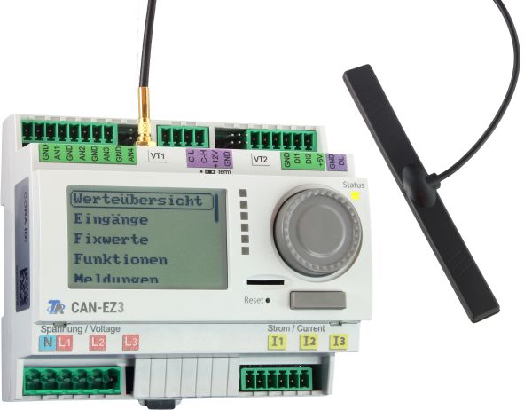
Table of contents Manual Version 1.15.4
Safety requirements . . . . . . . . . . . . . . . . . . . . . . . . . . . . . . . . . . . . . . . . . . . . . . . . . . . . . . . . . . . 6
Maintenance . . . . . . . . . . . . . . . . . . . . . . . . . . . . . . . . . . . . . . . . . . . . . . . . . . . . . . . . . . . . . . . . . . . 6
Disposal . . . . . . . . . . . . . . . . . . . . . . . . . . . . . . . . . . . . . . . . . . . . . . . . . . . . . . . . . . . . . . . . . . . . . . 6
Function description . . . . . . . . . . . . . . . . . . . . . . . . . . . . . . . . . . . . . . . . . . . . . . . . . . . . . . . . . . . 7
Installation and connection . . . . . . . . . . . . . . . . . . . . . . . . . . . . . . . . . . . . . . . . . . . . . . . . . . . . . . 8
Power supply . . . . . . . . . . . . . . . . . . . . . . . . . . . . . . . . . . . . . . . . . . . . . . . . . . . . . . . . . . . . . . . . . . 8
Time stamp . . . . . . . . . . . . . . . . . . . . . . . . . . . . . . . . . . . . . . . . . . . . . . . . . . . . . . . . . . . . . . . . . . . . 8
General connection of the CAN-EZ3 . . . . . . . . . . . . . . . . . . . . . . . . . . . . . . . . . . . . . . . . . . . . . . . . . 9
Sensor, DL bus and CAN bus connections . . . . . . . . . . . . . . . . . . . . . . . . . . . . . . . . . . . . . . . . . . . 10
Sensor connection FTS... to VT1 or VT2 . . . . . . . . . . . . . . . . . . . . . . . . . . . . . . . . . . . . . . . . . . 11
Electrical measuring . . . . . . . . . . . . . . . . . . . . . . . . . . . . . . . . . . . . . . . . . . . . . . . . . . . . . . . . . . . . 11
3-phase measuring . . . . . . . . . . . . . . . . . . . . . . . . . . . . . . . . . . . . . . . . . . . . . . . . . . . . . . . . . . 11
1-phase measuring . . . . . . . . . . . . . . . . . . . . . . . . . . . . . . . . . . . . . . . . . . . . . . . . . . . . . . . . . . 11
External hinged current transformers . . . . . . . . . . . . . . . . . . . . . . . . . . . . . . . . . . . . . . . . . . . . 12
Sensor installation . . . . . . . . . . . . . . . . . . . . . . . . . . . . . . . . . . . . . . . . . . . . . . . . . . . . . . . . . . . . . 13
Sensorleitungen . . . . . . . . . . . . . . . . . . . . . . . . . . . . . . . . . . . . . . . . . . . . . . . . . . . . . . . . . . . . . . . 14
Data link for DL bus . . . . . . . . . . . . . . . . . . . . . . . . . . . . . . . . . . . . . . . . . . . . . . . . . . . . . . . . . . . . 15
Bus load from DL sensors . . . . . . . . . . . . . . . . . . . . . . . . . . . . . . . . . . . . . . . . . . . . . . . . . . . . . 15
Terminal diagram, DL bus data link . . . . . . . . . . . . . . . . . . . . . . . . . . . . . . . . . . . . . . . . . . . . . . 15
CAN Bus network . . . . . . . . . . . . . . . . . . . . . . . . . . . . . . . . . . . . . . . . . . . . . . . . . . . . . . . . . . . . . . 16
Wireless system (CORA) . . . . . . . . . . . . . . . . . . . . . . . . . . . . . . . . . . . . . . . . . . . . . . . . . . . . . . . 20
Principles . . . . . . . . . . . . . . . . . . . . . . . . . . . . . . . . . . . . . . . . . . . . . . . . . . . . . . . . . . . . . . . . . . . . 20
Pairing CORA devices . . . . . . . . . . . . . . . . . . . . . . . . . . . . . . . . . . . . . . . . . . . . . . . . . . . . . . . . . . . 20
Relaying wireless signals . . . . . . . . . . . . . . . . . . . . . . . . . . . . . . . . . . . . . . . . . . . . . . . . . . . . . . . . 21
Deleting a pairing . . . . . . . . . . . . . . . . . . . . . . . . . . . . . . . . . . . . . . . . . . . . . . . . . . . . . . . . . . . . . . 21
CORA-DL (cable instead of wireless) . . . . . . . . . . . . . . . . . . . . . . . . . . . . . . . . . . . . . . . . . . . . . . . 22
Installation . . . . . . . . . . . . . . . . . . . . . . . . . . . . . . . . . . . . . . . . . . . . . . . . . . . . . . . . . . . . . . . . . 22
Operation and programming . . . . . . . . . . . . . . . . . . . . . . . . . . . . . . . . . . . . . . . . . . . . . . . . . . . . 23
Inputs . . . . . . . . . . . . . . . . . . . . . . . . . . . . . . . . . . . . . . . . . . . . . . . . . . . . . . . . . . . . . . . . . . . . . . . 23
Default settings . . . . . . . . . . . . . . . . . . . . . . . . . . . . . . . . . . . . . . . . . . . . . . . . . . . . . . . . . . . . . . . 24
Functions . . . . . . . . . . . . . . . . . . . . . . . . . . . . . . . . . . . . . . . . . . . . . . . . . . . . . . . . . . . . . . . . . . 26
Definitions . . . . . . . . . . . . . . . . . . . . . . . . . . . . . . . . . . . . . . . . . . . . . . . . . . . . . . . . . . . . . . . . . 26
COP value (COP= Coefficient of Performance) . . . . . . . . . . . . . . . . . . . . . . . . . . . . . . . . . . . 26
Performance factor β . . . . . . . . . . . . . . . . . . . . . . . . . . . . . . . . . . . . . . . . . . . . . . . . . . . . . . 26
Energy manager . . . . . . . . . . . . . . . . . . . . . . . . . . . . . . . . . . . . . . . . . . . . . . . . . . . . . . . . . . . . . . . 27
Output control . . . . . . . . . . . . . . . . . . . . . . . . . . . . . . . . . . . . . . . . . . . . . . . . . . . . . . . . . . . . . . . . . 29
Energy meter . . . . . . . . . . . . . . . . . . . . . . . . . . . . . . . . . . . . . . . . . . . . . . . . . . . . . . . . . . . . . . . . . 31
Heat meter . . . . . . . . . . . . . . . . . . . . . . . . . . . . . . . . . . . . . . . . . . . . . . . . . . . . . . . . . . . . . . . . . . . 33
Date-specific memory . . . . . . . . . . . . . . . . . . . . . . . . . . . . . . . . . . . . . . . . . . . . . . . . . . . . . . . . . . . 37
Mathematics function . . . . . . . . . . . . . . . . . . . . . . . . . . . . . . . . . . . . . . . . . . . . . . . . . . . . . . . . . . 39
Notes on accuracy . . . . . . . . . . . . . . . . . . . . . . . . . . . . . . . . . . . . . . . . . . . . . . . . . . . . . . . . . . . . 42
Reset . . . . . . . . . . . . . . . . . . . . . . . . . . . . . . . . . . . . . . . . . . . . . . . . . . . . . . . . . . . . . . . . . . . . . . 43
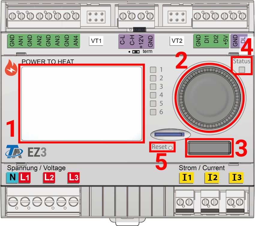
LED status indicators . . . . . . . . . . . . . . . . . . . . . . . . . . . . . . . . . . . . . . . . . . . . . . . . . . . . . . . . . . 43
LED indicators at device start-up . . . . . . . . . . . . . . . . . . . . . . . . . . . . . . . . . . . . . . . . . . . . . . . . . . 43
Basics . . . . . . . . . . . . . . . . . . . . . . . . . . . . . . . . . . . . . . . . . . . . . . . . . . . . . . . . . . . . . . . . . . . . . 44
Device overview . . . . . . . . . . . . . . . . . . . . . . . . . . . . . . . . . . . . . . . . . . . . . . . . . . . . . . . . . . . . . . . 44
LED indicator light . . . . . . . . . . . . . . . . . . . . . . . . . . . . . . . . . . . . . . . . . . . . . . . . . . . . . . . . . . . . . 45
General information on programming parameters . . . . . . . . . . . . . . . . . . . . . . . . . . . . . . . . . . . . . 46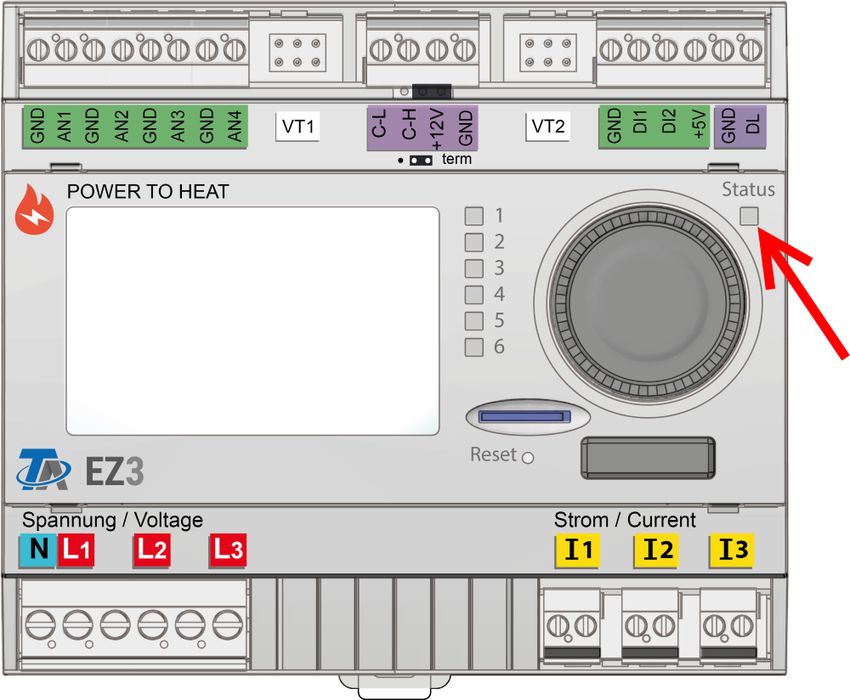
Table of contents
   Designations . . . . . . . . . . . . . . . . . . . . . . . . . . . . . . . . . . . . . . . . . . . . . . . . . . . . . . . . . . . . . . . . . .     47
Date / time / location . . . . . . . . . . . . . . . . . . . . . . . . . . . . . . . . . . . . . . . . . . . . . . . . . . . . . . . . . .              48
Value summary . . . . . . . . . . . . . . . . . . . . . . . . . . . . . . . . . . . . . . . . . . . . . . . . . . . . . . . . . . . . . .               49
Inputs . . . . . . . . . . . . . . . . . . . . . . . . . . . . . . . . . . . . . . . . . . . . . . . . . . . . . . . . . . . . . . . . . . . . .        50
   Programming the parameters . . . . . . . . . . . . . . . . . . . . . . . . . . . . . . . . . . . . . . . . . . . . . . . . . . . . .                 50
      Sensor type and measured variable . . . . . . . . . . . . . . . . . . . . . . . . . . . . . . . . . . . . . . . . . . . . . .                     50
      Designation . . . . . . . . . . . . . . . . . . . . . . . . . . . . . . . . . . . . . . . . . . . . . . . . . . . . . . . . . . . . . . . .       53
      Sensor correction . . . . . . . . . . . . . . . . . . . . . . . . . . . . . . . . . . . . . . . . . . . . . . . . . . . . . . . . . . .           53
      Average . . . . . . . . . . . . . . . . . . . . . . . . . . . . . . . . . . . . . . . . . . . . . . . . . . . . . . . . . . . . . . . . . . .     53
      Sensor check for analogue sensors . . . . . . . . . . . . . . . . . . . . . . . . . . . . . . . . . . . . . . . . . . . . .                       54
          Sensor error . . . . . . . . . . . . . . . . . . . . . . . . . . . . . . . . . . . . . . . . . . . . . . . . . . . . . . . . . . . . .        54
      Zuordnung der möglichen Sensortypen zu den Eingängen . . . . . . . . . . . . . . . . . . . . . . . . . . . .                                      55
      Resistance table for various sensor types . . . . . . . . . . . . . . . . . . . . . . . . . . . . . . . . . . . . . . . . .                       55
          NTC sensors . . . . . . . . . . . . . . . . . . . . . . . . . . . . . . . . . . . . . . . . . . . . . . . . . . . . . . . . . . . . .         56
          PTC sensors . . . . . . . . . . . . . . . . . . . . . . . . . . . . . . . . . . . . . . . . . . . . . . . . . . . . . . . . . . . . .         56
Fixed value . . . . . . . . . . . . . . . . . . . . . . . . . . . . . . . . . . . . . . . . . . . . . . . . . . . . . . . . . . . . . . . . .           57
   Programming the parameters . . . . . . . . . . . . . . . . . . . . . . . . . . . . . . . . . . . . . . . . . . . . . . . . . . . . .                 58
      Fixed value type . . . . . . . . . . . . . . . . . . . . . . . . . . . . . . . . . . . . . . . . . . . . . . . . . . . . . . . . . . . . .        58
      Digital . . . . . . . . . . . . . . . . . . . . . . . . . . . . . . . . . . . . . . . . . . . . . . . . . . . . . . . . . . . . . . . . . . . .   58
      Analogue . . . . . . . . . . . . . . . . . . . . . . . . . . . . . . . . . . . . . . . . . . . . . . . . . . . . . . . . . . . . . . . . . .      59
      Pulse . . . . . . . . . . . . . . . . . . . . . . . . . . . . . . . . . . . . . . . . . . . . . . . . . . . . . . . . . . . . . . . . . . . . .   60
         Function quantity . . . . . . . . . . . . . . . . . . . . . . . . . . . . . . . . . . . . . . . . . . . . . . . . . . . . . . . . .            60
      Designation . . . . . . . . . . . . . . . . . . . . . . . . . . . . . . . . . . . . . . . . . . . . . . . . . . . . . . . . . . . . . . . .       60
      Restriction of change authority . . . . . . . . . . . . . . . . . . . . . . . . . . . . . . . . . . . . . . . . . . . . . . . . .                 60
Functions . . . . . . . . . . . . . . . . . . . . . . . . . . . . . . . . . . . . . . . . . . . . . . . . . . . . . . . . . . . . . . . . . .           61
Messages . . . . . . . . . . . . . . . . . . . . . . . . . . . . . . . . . . . . . . . . . . . . . . . . . . . . . . . . . . . . . . . . . .            62
CAN bus . . . . . . . . . . . . . . . . . . . . . . . . . . . . . . . . . . . . . . . . . . . . . . . . . . . . . . . . . . . . . . . . . . .           63
   Datalogging . . . . . . . . . . . . . . . . . . . . . . . . . . . . . . . . . . . . . . . . . . . . . . . . . . . . . . . . . . . . . . . . . .      64
      Datalogging Settings . . . . . . . . . . . . . . . . . . . . . . . . . . . . . . . . . . . . . . . . . . . . . . . . . . . . . . . . .            64
      Datalogging Analogue/Digital . . . . . . . . . . . . . . . . . . . . . . . . . . . . . . . . . . . . . . . . . . . . . . . . . .                  64
   CAN settings . . . . . . . . . . . . . . . . . . . . . . . . . . . . . . . . . . . . . . . . . . . . . . . . . . . . . . . . . . . . . . . . . .     65
   CAN analogue inputs . . . . . . . . . . . . . . . . . . . . . . . . . . . . . . . . . . . . . . . . . . . . . . . . . . . . . . . . . . .            66
      Node number . . . . . . . . . . . . . . . . . . . . . . . . . . . . . . . . . . . . . . . . . . . . . . . . . . . . . . . . . . . . . . .         66
      Designation . . . . . . . . . . . . . . . . . . . . . . . . . . . . . . . . . . . . . . . . . . . . . . . . . . . . . . . . . . . . . . . .       66
      CAN bus timeout . . . . . . . . . . . . . . . . . . . . . . . . . . . . . . . . . . . . . . . . . . . . . . . . . . . . . . . . . . . .           67
      Sensor check . . . . . . . . . . . . . . . . . . . . . . . . . . . . . . . . . . . . . . . . . . . . . . . . . . . . . . . . . . . . . . .        67
      Measured variable . . . . . . . . . . . . . . . . . . . . . . . . . . . . . . . . . . . . . . . . . . . . . . . . . . . . . . . . . . .           67
      Value at timeout . . . . . . . . . . . . . . . . . . . . . . . . . . . . . . . . . . . . . . . . . . . . . . . . . . . . . . . . . . . .          68
      Sensor correction . . . . . . . . . . . . . . . . . . . . . . . . . . . . . . . . . . . . . . . . . . . . . . . . . . . . . . . . . . .           68
      Sensor error . . . . . . . . . . . . . . . . . . . . . . . . . . . . . . . . . . . . . . . . . . . . . . . . . . . . . . . . . . . . . . . .      68
   CAN digital inputs . . . . . . . . . . . . . . . . . . . . . . . . . . . . . . . . . . . . . . . . . . . . . . . . . . . . . . . . . . . . . .       69
   CAN analogue outputs . . . . . . . . . . . . . . . . . . . . . . . . . . . . . . . . . . . . . . . . . . . . . . . . . . . . . . . . . .             69
      Designation . . . . . . . . . . . . . . . . . . . . . . . . . . . . . . . . . . . . . . . . . . . . . . . . . . . . . . . . . . . . . . . .       70
      Transmission condition . . . . . . . . . . . . . . . . . . . . . . . . . . . . . . . . . . . . . . . . . . . . . . . . . . . . . . .              70
   CAN digital outputs . . . . . . . . . . . . . . . . . . . . . . . . . . . . . . . . . . . . . . . . . . . . . . . . . . . . . . . . . . . .          71
      Designation and transmission condition . . . . . . . . . . . . . . . . . . . . . . . . . . . . . . . . . . . . . . . . . .                        71
   Active CAN nodes . . . . . . . . . . . . . . . . . . . . . . . . . . . . . . . . . . . . . . . . . . . . . . . . . . . . . . . . . . . . . .         71
DL-Bus . . . . . . . . . . . . . . . . . . . . . . . . . . . . . . . . . . . . . . . . . . . . . . . . . . . . . . . . . . . . . . . . . . . .          72
   DL settings . . . . . . . . . . . . . . . . . . . . . . . . . . . . . . . . . . . . . . . . . . . . . . . . . . . . . . . . . . . . . . . . . . .    72
Table of contents
  DL input . . . . . . . . . . . . . . . . . . . . . . . . . . . . . . . . . . . . . . . . . . . . . . . . . . . . . . . . . . . . . . . . . . . . .      73
      DL bus address and DL bus index . . . . . . . . . . . . . . . . . . . . . . . . . . . . . . . . . . . . . . . . . . . . . . .                       73
      Designation . . . . . . . . . . . . . . . . . . . . . . . . . . . . . . . . . . . . . . . . . . . . . . . . . . . . . . . . . . . . . . . .         74
      DL bus timeout . . . . . . . . . . . . . . . . . . . . . . . . . . . . . . . . . . . . . . . . . . . . . . . . . . . . . . . . . . . . . .          74
      Sensor check . . . . . . . . . . . . . . . . . . . . . . . . . . . . . . . . . . . . . . . . . . . . . . . . . . . . . . . . . . . . . . .          74
      Measured variable . . . . . . . . . . . . . . . . . . . . . . . . . . . . . . . . . . . . . . . . . . . . . . . . . . . . . . . . . . .             74
      Value at timeout . . . . . . . . . . . . . . . . . . . . . . . . . . . . . . . . . . . . . . . . . . . . . . . . . . . . . . . . . . . .            74
      Sensor correction . . . . . . . . . . . . . . . . . . . . . . . . . . . . . . . . . . . . . . . . . . . . . . . . . . . . . . . . . . .             75
      Sensor error . . . . . . . . . . . . . . . . . . . . . . . . . . . . . . . . . . . . . . . . . . . . . . . . . . . . . . . . . . . . . . . .        75
      DL digital inputs . . . . . . . . . . . . . . . . . . . . . . . . . . . . . . . . . . . . . . . . . . . . . . . . . . . . . . . . . . . . .         75
  Bus load of DL sensors . . . . . . . . . . . . . . . . . . . . . . . . . . . . . . . . . . . . . . . . . . . . . . . . . . . . . . . . . .              75
  DL output . . . . . . . . . . . . . . . . . . . . . . . . . . . . . . . . . . . . . . . . . . . . . . . . . . . . . . . . . . . . . . . . . . . .       76
      Designation and destination address . . . . . . . . . . . . . . . . . . . . . . . . . . . . . . . . . . . . . . . . . . . .                         76
CORA devices . . . . . . . . . . . . . . . . . . . . . . . . . . . . . . . . . . . . . . . . . . . . . . . . . . . . . . . . . . . . . . .                77
  fiD sub-menu . . . . . . . . . . . . . . . . . . . . . . . . . . . . . . . . . . . . . . . . . . . . . . . . . . . . . . . . . . . . . . . . .          77
  Input variables . . . . . . . . . . . . . . . . . . . . . . . . . . . . . . . . . . . . . . . . . . . . . . . . . . . . . . . . . . . . . . . .         77
  Parameters . . . . . . . . . . . . . . . . . . . . . . . . . . . . . . . . . . . . . . . . . . . . . . . . . . . . . . . . . . . . . . . . . . .        78
  Output variables . . . . . . . . . . . . . . . . . . . . . . . . . . . . . . . . . . . . . . . . . . . . . . . . . . . . . . . . . . . . . . .          78
General settings . . . . . . . . . . . . . . . . . . . . . . . . . . . . . . . . . . . . . . . . . . . . . . . . . . . . . . . . . . . . .                79
  Current transformer . . . . . . . . . . . . . . . . . . . . . . . . . . . . . . . . . . . . . . . . . . . . . . . . . . . . . . . . . . . .             79
  Phase simulation . . . . . . . . . . . . . . . . . . . . . . . . . . . . . . . . . . . . . . . . . . . . . . . . . . . . . . . . . . . . . .            79
  Language . . . . . . . . . . . . . . . . . . . . . . . . . . . . . . . . . . . . . . . . . . . . . . . . . . . . . . . . . . . . . . . . . . . .        79
  Brightness . . . . . . . . . . . . . . . . . . . . . . . . . . . . . . . . . . . . . . . . . . . . . . . . . . . . . . . . . . . . . . . . . . .        79
  Display timeout . . . . . . . . . . . . . . . . . . . . . . . . . . . . . . . . . . . . . . . . . . . . . . . . . . . . . . . . . . . . . . . .         79
  Simulation . . . . . . . . . . . . . . . . . . . . . . . . . . . . . . . . . . . . . . . . . . . . . . . . . . . . . . . . . . . . . . . . . . .        80
  Currency . . . . . . . . . . . . . . . . . . . . . . . . . . . . . . . . . . . . . . . . . . . . . . . . . . . . . . . . . . . . . . . . . . . . .      80
  Access to menu . . . . . . . . . . . . . . . . . . . . . . . . . . . . . . . . . . . . . . . . . . . . . . . . . . . . . . . . . . . . . . .            80
  User defined designations . . . . . . . . . . . . . . . . . . . . . . . . . . . . . . . . . . . . . . . . . . . . . . . . . . . . . . .                 81
User . . . . . . . . . . . . . . . . . . . . . . . . . . . . . . . . . . . . . . . . . . . . . . . . . . . . . . . . . . . . . . . . . . . . . .          82
  Current user . . . . . . . . . . . . . . . . . . . . . . . . . . . . . . . . . . . . . . . . . . . . . . . . . . . . . . . . . . . . . . . . . .        82
  Changing the password . . . . . . . . . . . . . . . . . . . . . . . . . . . . . . . . . . . . . . . . . . . . . . . . . . . . . . . . .                 82
Version and serial number . . . . . . . . . . . . . . . . . . . . . . . . . . . . . . . . . . . . . . . . . . . . . . . . . . . . . .                     84
Data administration . . . . . . . . . . . . . . . . . . . . . . . . . . . . . . . . . . . . . . . . . . . . . . . . . . . . . . . . . . .                 85
  Function data . . . . . . . . . . . . . . . . . . . . . . . . . . . . . . . . . . . . . . . . . . . . . . . . . . . . . . . . . . . . . . . . .         85
      Load... . . . . . . . . . . . . . . . . . . . . . . . . . . . . . . . . . . . . . . . . . . . . . . . . . . . . . . . . . . . . . . . . . . . .     86
      Deleting, renaming and sending saved files . . . . . . . . . . . . . . . . . . . . . . . . . . . . . . . . . . . . . . .                            87
      Save... . . . . . . . . . . . . . . . . . . . . . . . . . . . . . . . . . . . . . . . . . . . . . . . . . . . . . . . . . . . . . . . . . . . .     88
  Firmware Load… . . . . . . . . . . . . . . . . . . . . . . . . . . . . . . . . . . . . . . . . . . . . . . . . . . . . . . . . . . . . . . .            89
  Status . . . . . . . . . . . . . . . . . . . . . . . . . . . . . . . . . . . . . . . . . . . . . . . . . . . . . . . . . . . . . . . . . . . . . . .    89
  Total reset . . . . . . . . . . . . . . . . . . . . . . . . . . . . . . . . . . . . . . . . . . . . . . . . . . . . . . . . . . . . . . . . . . .       90
  Restart . . . . . . . . . . . . . . . . . . . . . . . . . . . . . . . . . . . . . . . . . . . . . . . . . . . . . . . . . . . . . . . . . . . . . .     90
  Reset . . . . . . . . . . . . . . . . . . . . . . . . . . . . . . . . . . . . . . . . . . . . . . . . . . . . . . . . . . . . . . . . . . . . . . . .   90
  Change-Log . . . . . . . . . . . . . . . . . . . . . . . . . . . . . . . . . . . . . . . . . . . . . . . . . . . . . . . . . . . . . . . . . .          90
System values . . . . . . . . . . . . . . . . . . . . . . . . . . . . . . . . . . . . . . . . . . . . . . . . . . . . . . . . . . . . . . .               91
Technical data . . . . . . . . . . . . . . . . . . . . . . . . . . . . . . . . . . . . . . . . . . . . . . . . . . . . . . . . . . . . . . .              93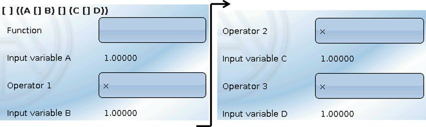
Safety requirements
                 All installation and wiring work on the controller must only be carried out in a zero volt
                 state. The opening, connection and commissioning of the device may only be carried
                 out by competent personnel. While doing so, they must observe all local safety re-
                 quirements.

This device is state of the art and meets all necessary safety regulations. It may only be used in accord-
ance with the technical data and the safety requirements and regulations listed below. When using the
device, also observe the statutory and safety regulations apposite to the particular use. Any other use will
automatically void all warranty rights.
• The device must only be installed in a dry interior room.
• In accordance with local regulations, it must be possible to isolate the 230 V cable to the energy
   meter from the mains using an omnipolar isolating facility (connector/socket or 2-pole isolator).
• Never interchange the safety low voltage connections (e.g. sensor connections) with the 230 V
   connections. Destruction and life threatening voltages at the device and the connected sensors
   may occur.
• Safe operation is no longer possible if the controller or connected equipment exhibits visual
   damage, no longer functions or has been stored for lengthy periods in unsuitable conditions. If
   this is the case, disable the controller and equipment and secure against unintentional use.
• Heat-sensitive system components (e.g. plastic pipes) must be equipped with safety devices
   (e.g. thermal high limit safety cut-out for underfloor heating), which prevent overheating in the
   event of a fault in the controller or another system component.

Maintenance
If treated and used correctly, the device will not require any maintenance. Use a cloth moistened with mild
alcohol (such as methylated spirits) to clean. Never use corrosive cleaning agents or solvents such as
chloroethylene or trichloroethylene.
No components relevant to long term accuracy are subject to loading if the device is used correctly. Con-
sequently long term drift is extremely low. The device therefore cannot be calibrated. Thus applying any
compensation is impossible.
The design characteristics of the device must not be changed during repairs. Spare parts must corre-
spond to the original spare parts and must be used in accordance with the build version.

Disposal
                   • Devices no longer in use or beyond a state of repair must be disposed of in an en-
                   vironmentally responsible manner by an authorised collection point. They must never
                   be treated as ordinary household waste.
                   • We can undertake the environmentally responsible disposal of devices sold by the
                   Technischen Alternative company upon request.
                   • Packaging material must be disposed of in an environmentally responsible manner.
                   • Incorrect disposal may result in considerable damage to the environment, as many of
                   the materials used require professional handling.

   6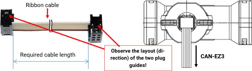
Function description

Function description
The main purpose of the CAN-EZ3 energy meter is energy management in conjunction with several
EHS(-R) electric immersion heaters and other actuators, as well as metering energy and heat.

Energy management primarily includes current measurement in the building and the corresponding
control of immersion heaters (and other consumers) for the use of surplus energy yields in the form
of DHW storage, instead of exporting it to the mains, which can be less profitable.

As the CAN-EZ3 has the full functionality of the x2 series and multiple sensor inputs, other tasks such
as heat and energy metering are also possible. However, only specific functions are used for the ac-
tual purpose of the energy meter and these are described in these instructions.

For tasks such as heat metering, 4 analogue inputs for temperature sensors, 2 inputs for VSG flow
rate transducers or FTS flow sensors and a DL bus interface for DL sensors are available.
The CAN-EZ3 is programmed either with TAPPS2, directly via the display and buttons on the energy
meter or remotely via the UVR16x2 controller, the CAN-MTx2 CAN monitor or the C.M.I.
Input values, system values from electrical measuring and results of the metering and functions can
be relayed to other devices via the CAN bus.
The same applies to values from inputs that are not used for any metering (e.g. in the case of a CAN
I/O module).
The CAN-EZ3 has no outputs.
The CAN-EZ3 is not calibrated and consequently may not be used for billing purposes.

                                                                                                     7
Installation and connection

Installation and connection
The CAN-EZ3 is installed in a meter box in accordance with local regulations. It can be snapped on
to a top-hat rail (DIN support rail TS35 to EN 50022).
The 2-pole connectors of the current transformers are connected to the CAN-EZ3 and folded over the
cores. When doing this, pay attention to the correct assignment (I1 - I3) in accordance with the volt-
age connections and a positive phase sequence.

 Caution! The surfaces of the current transformer ferrite cores must be completely clean. Even tiny
 dust particles or greasy films can severely affect the measuring result. These surfaces must there-
 fore be cleaned with a clean, lint-free cloth or clean fingers before closing.

For voltage measuring, the required wires are connected to the voltage terminals in the CAN-EZ3.
The connection of sensors, and CAN and DL buses is carried out using the supplied connectors

Power supply
The CAN-EZ3 is supplied with power via the voltage measuring connection U1 (first phase).

Time stamp
The CAN-EZ3 has a real time clock and, as node 1 in the CAN bus network, can therefore transmit the
time and date to other devices.

8

Installation and connection

General connection of the CAN-EZ3
The CAN-EZ3 must always be connected by qualified personnel, taking into account the conditions
on site and local safety regulations. The safety requirements on page 6 must also be observed.
The following diagram is only an example of the installation of a CAN-EZ3 in a typical TN-S system
with surplus power supply.
     Device for grid monitoring with associat-

     Electricity meter of the energy supplier
     Normal supply main switches

     Miniature circuit breaker
     Residual current device
     Grid connection fuses

     ed switching element
     NZHS

                           MCB
     HAS
     ENS

                           Wh
                           FI

                                                                                                   9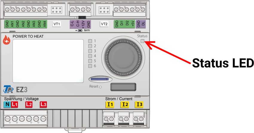
Installation and connection
Sensor, DL bus and CAN bus connections
Ext. connection antenna
Sensor inputs S1 - S4 VT1 CAN bus VT2 Modbus DL bus
Sensor inputs 1-4
AN1 - AN4 Parameterisation in the Inputs (1-4) menu
Connection of sensors between AN1/2/3/4 and sensor earth
Special connection for FTS flow sensors (excl. DL) and other DL sensors
Parameterisation: Inputs menu
Inputs 5-6 for temperature (sensor PT1000)
Inputs 7-8 for flow rate and selection of the sensor (DN) or digital signals (S0)
+5V (for FTS)
VT1 & VT2 Analogue input (S5/S6) GND
GND GND
Digital input (S7/S8)
Connection between each sensor Sx and earth GND.
The earth connection (GND) is looped.
CAN bus CAN-Low, CAN-High, +12 V, earth
(C-L, C-H The principles of bus cabling are described extensively in the manuals for the free-
+12 V, GND) ly programmable controllers and must be observed.
Modbus Interface for Modbus RTU485 (as master or slave)
DL bus interface for DL sensors (e.g. FTS-DL (with intermediate board))
DL bus Parameterisation: DL bus menu (any analogue input)
Connection between DL and GND
No screws should be used to secure the antenna cable – press and pull to con-
Ext. connec-
nect and terminate. The antenna itself is intended for mounting outside the meter
tion Antenna
box. The antenna should not be fitted directly on metal (e.g. meter box).
The connection for S0 signals is located on the device's lower terminal strip
(graphic on page 11).
S0
This input can capture pulses with max. 20 Hz and a pulse duration of at least 25
ms.
10Installation and connection
Sensor connection FTS... to VT1 or VT2
The volume flow sensors are connected directly to the CAN-EZ3, without intermediate board. The
supplied ribbon cable is adjusted to the required length on site. For this, the 2nd plug is pressed on
to the cable according to the following drawing.
Electrical measuring
3-phase measuring
All 3 phase conductors (L1 - L3) are connected to voltage terminals L1-L3 and the neutral conductor
to the N terminal. The 3 external hinged current transformers are connected to terminals I1 – I3 in
the correct sequence and folded over the wires to be measured.
For single measurements, it is possible to set the "Phase simulation" parameter in the General set-
tings to "Yes". In this case, the values (voltage / cos phi / output) for L2 and L3 are simulated inter-
nally using L1. Phase simulation is based on a clockwise rotating field, therefore a clockwise rotating
field must also be observed for current measurement at I2 and I3.
This results in less precise measuring. When phase simulation is activated, phases L2 and L3 are
output as 0. When phase simulation is deactivated, the high-resistance voltage input may result in
random values being displayed at L2 and L3 due to interference effects. This can be eliminated by
additionally routing the neutral conductor N to voltage inputs L2 and L3.
1-phase measuring
Only the phase conductor (to voltage terminal L1) and the neutral conductor N are connected. An ex-
ternal hinged current transformer is connected to terminal I1 and folded over the wire to be meas-
ured.
The "Phase simulation" parameter is irrelevant for this.
11Installation and connection
External hinged current transformers
Ensure that the current transformers are assigned correctly (I1 to L1, I2 to L2 and I3 to L3) and that
the energy direction is observed.
PLEASE NOTE: Before snapping the current transformer onto the phase conductors, they must al-
ready be connected to the CAN-EZ3. Otherwise the current transformers can be damaged.
Each external current transformer is labelled with "K L", whereby the energy direction must be
from K to L for positive metering.
The poles of the cable connecting the electricity sensor and the energy meter must not be swapped.
The white cable must be on the left and the black cable on the right.
This cable is either white
or red.
Mains side building side
energy direction
Each current transformer must be closed carefully by clicking the snap fastener securely into place.
If the energy direction is changed, the energy meter counts in the negative.
12Installation and connection – Sensor connection
Sensor installation
Correct arrangement and installation of the sensors is extremely important for correct functioning of
the system. To this end, also ensure that they are completely inserted in their sensor wells. The cable
fittings provided serve as strain relief. When used outdoors, no water must be allowed to penetrate
the sensor wells (risk of frost). The contact sensors must be insulated well to protect them from be-
ing influenced by the ambient temperature.
Fundamentally, sensors should not be exposed to moisture (such as condensation) since this can
diffuse through the cast resin and damage the sensor. If this happens, heating the sensor to 90 °C
for an hour may help. When using sensor wells in stainless steel cylinders or swimming pools, par-
ticular attention must be given to their corrosion resistance.
• Collector sensor (grey lead with junction box): Either insert into a pipe which is brazed or riveted
directly to the absorber and protrudes from the collector housing, or insert a tee into the flow
manifold of the outermost collector into which the sensor well, together with the brass cable fit-
ting (= protection against moisture), can be inserted; then insert the sensor. To protect against
lightning damage, the junction box has a surge protection (voltage dependent resistor) which is
clamped in parallel between the sensor and the extension cable.
• Boiler sensor (boiler flow): This sensor is either inserted into a sensor well in the boiler or fitted
to the flow line as close to the boiler as possible.
• DHW cylinder sensor: The sensor required for the solar thermal system should be used with a
sensor well for finned tube heat exchangers just above the exchanger or, if integrated smooth
tube heat exchangers are used, in the lower third of the exchanger or the exchanger’s return out-
let so that the sensor well protrudes into the heat exchanger tube. The sensor monitoring the
heating of the DHW cylinder by the boiler is installed at a level corresponding to the amount of
domestic hot water required during the heating season. The supplied cable fitting acts as strain
relief. Installation below the associated coil or heat exchanger is not permissible under any cir-
cumstances.
• Buffer sensor: The sensor required for the solar thermal system is fitted in the lower section of
the cylinder just above the solar indirect coil using the sensor well supplied. The supplied cable
fitting acts as strain relief. As the reference sensor for the heating system hydraulics, it is recom-
mended to insert the sensor into the sensor well between the centre and upper third of the buffer
cylinder, or positioned against the cylinder wall underneath the insulation.
• Pool sensor (swimming pool): Fit a tee into the suction line immediately on the pool outlet and
insert the sensor with a sensor well. In the process, ensure the material used is corrosion-resist-
ant. A further option would be to fit the sensor as a contact sensor with appropriate thermal insu-
lation against ambient influences.
• Contact sensor: Use scroll springs, pipe clips, etc.to attach the contact sensor to the respective
line. Ensure the material used is suitable (corrosion, temperature resistance, etc.). Then insulate
the sensor thoroughly so that the pipe temperature is captured accurately and ambient tempera-
tures cannot falsify the result.
• DHW sensor: A rapid reaction to changes in the water volume is extremely important when using
the controller in systems that generate domestic hot water by means of an external heat
exchanger and variable speed pump (freshwater module). Therefore fit the DHW sensor directly
on the heat exchanger outlet. This ultra-quick sensor (special accessory, type MSP ...) should
protrude into the output with the aid of a tee sealed in with an O-ring. The heat exchanger should
be installed upright with the DHW outlet at the top.
• Radiation sensor: The parallel collector orientation is important in order to obtain a measure-
ment that corresponds to the collector position. Consequently it should be secured to the sheet
steel covering or adjacent to the collector on an extension of the mounting rail. To this end, the
sensor casing has a blind hole that can be opened at any time. The sensor is also available as a
wireless version.
13Installation and connection – Sensor connection • Room sensor: This sensor is intended for installation in the living space (reference room). Do not install the room sensor near a heat source or window. By simply replugging a jumper inside the sensor, each room sensor can also be used exclusively as a remote adjuster (no room tempera- ture influence). It is only suitable for operation in dry rooms. The sensor is also available as a wireless version. • Outside temperature sensor: This sensor is installed on the coldest wall (usually facing north) some two meters above the ground. Avoid temperature influences from nearby air shafts, open windows, cable ways, etc. It must not be subjected to direct insolation. Sensorleitungen All sensor leads with a cross-section of 0.5 mm2 can be extended to up to 50 metres. With this lead length and a PT1000 temperature sensor, the measuring error is approximately +1 K. A correspond- ingly larger cross-section is required for longer leads or a lesser measuring error. In order to prevent measurement fluctuations and ensure perfect signal transmission, sensor leads must not be sub- jected to external negative influences. When using non-screened cables, route sensor leads and 230 V cables either in separate cable conduits or with a minimum clearance of 5 cm. If screened cables are used, the screen must be connected to the sensor earth. 14
Installation and connection – DL bus

Data link for DL bus
The DL bus has only 2 wires: DL and GND (sensor earth). The DL bus itself supplies the power supply
for the DL bus sensors.
Cables can be routed with a star topology or in series (from one device to the next).
Any cable with a cross-section of 0.75 mm² up to 30 m in length can be used as a data link. Over 30
m, the use of a shielded cable is recommended, increasing the permissible cable length to 100 m.
Long cable conduits routed closely next to each other for mains and data links result in faults being
induced into the data link from the mains. We therefore recommend a minimum clearance of 20 cm
between two cable conduits or the use of screened cables.
Use separate, screened cables when capturing data from two controllers with a single datalogger.
Never run the data link together with a CAN bus cable in the same conduit.

Bus load from DL sensors
A 2-pole cable provides both the power supply and the signal transfer from DL bus sensors. An ad-
ditional power supply by means of an external power supply unit (such as with the CAN bus) is not
possible.
Take the "bus load" into consideration as sensors have a relatively high current demand:
The CAN-EZ3 energy meter provides a maximum bus load of 100 %. The bus loads of the electronic
sensors are listed in the technical data of the relevant sensors.
Example: The FTS4-50DL electronic sensor has a bus load of 25 %. Consequently, up to four FTS4-
50DL sensors can be connected to the DL bus.

Terminal diagram, DL bus data link

                                                                                                    15
Installation and connection – CAN bus
CAN Bus network
Terminal diagram, CAN Bus cable
Guidelines for the topology of CAN networks
Technical principles
The CAN bus comprises the cables CAN-High,
CAN-Low, GND and one +12 V supply cable for
bus components without their own power sup-
ply. The combined total load of all devices with
12 V and 24 V supply must not exceed 6 W.
Design CAN networks in a linear fashion and set
a terminator at each network termination. This
is ensured by the termination of the end devic-
es.
In the case of larger networks (covering several
buildings), problems can occur through electro-
magnetic interference and potential differenc-
es.
To avoid or to the greatest extent manage such
problems, take the following measures:
• Cable screening
The bus cable screen must be connected well at every node to provide continuity. For larger
networks we recommend including the screen in the equipotential bonding, in line with the
examples shown.
• Equipotential bonding
As low an ohm connection as possible to the earth potential is particularly important. Where
cables enter buildings, ensure that the cable entries are in the same location where possible
and that all are connected to the same equipotential bonding system (SingleEentryPoint prin-
ciple). The purpose is to create potentials that are as similar as possible, in order to achieve
the smallest possible potential difference to adjacent lines in case one line suffers a voltage
surge (lightning strike). Also ensure a corresponding clearance between the cable and light-
ning protection systems.
The equipotential bonding also has positive properties to counteract interferences emitted
from linked cables.
16Installation and connection – CAN bus
• Avoiding earth loops
Where a bus cable is routed between several buildings, ensure that earth loops are avoided.
The reason for this is that buildings actually have different potentials compared to the earth
potential. An earth loop is created when connecting one cable screen in each building
directly with the equipotential bonding system. In other words, a current flows from the
higher to the lower potential.
For example, if lightning strikes near one of the buildings, the potential of that building will
briefly be raised by several kV.
In this case, the equalizing current flows to earth via the bus screen and causes an extreme
electromagnetic input which can result in the destruction of the bus components.
Lightning protection
Efficient lighting protection is highly dependent on good building earthing that meets the relevant
regulations.
An external lightning protection system offers protection against a direct lightning strike.
In order to protect against voltage surges in the 230 V mains supply cable (indirect lightning strike),
appropriate lightning conductors and surge arresters compliant with local regulations must be fitted
in the upstream distribution systems.
In order to protect the individual components of a CAN network against indirect lightning strike, we
recommend the use of surge arresters specifically developed for bus systems.
Example: CAN bus surge arresters CAN-UES from Technische Alternative
Gas discharge arrester for indirect earthing EPCOS N81-A90X
Examples of different network versions
Key to symbols:
... device with its own power supply (RSM610, UVR16x2, UVR67 etc.)
... device is supplied by the bus (CAN-I/O 45, CAN-MTx2 etc.)
... terminated (end devices) ... open termination
... gas discharge arrester for indirect earthing
Max. cable length: 1000 m at 50 kbit/s
The screen must be continued at each network node and be connected to the device earth (GND).
The screen earthing or GND must only be implemented indirectly via a gas discharge arrester.
Ensure that no unintentional direct connection of earth or screen and the earth potential is created
(e.g. via sensors and the earthed pipework).
17Installation and connection – CAN bus
Cable selection and network topology
Screened twisted pairs have proven useful in CANopen networks. These are cables with twisted
pairs of conductors and a shared external screen. Such cables are relatively resistant to EMC inter-
ference and can still carry 50 kbit/s for up to 1000 m. The CANopen recommendations (CiA DR 303-
1) for cable cross-sections are given in the table below.
Bus length Resistance in terms Cross-section
[m] of length [mΩ/m] [mm2]
0...40 70 0,25...0,34
40...300 < 60 0,34...0,60
300...600 < 40 0,50...0,60
600...1000 < 26 0,75...0,80
The maximum cable length also depends on the number of nodes [n] linked with the bus cable and
the cable cross-section [mm²].
Cable cross-section Maximum length [m]
[mm2] n=32 n=63
0,25 200 170
0,50 360 310
0,75 550 470
Bus rate
In the CAN bus / CAN settings menu of the UVR16x2, the bus rate can be set to between 5 and 500
kbit/s, whereby lower bus rates enable longer cable networks. However, in this case, the cable cross-
section must be increased accordingly.
The standard bus rate of the CAN network is 50 kbit/s (50 kBaud), which is specified for many CAN
bus devices.
Important: All devices in the CAN bus network must have the same transfer rate in order to be able
to communicate with each other.
Bus rate [kbit/s] Maximum permissible total bus length [m]
5 10.000
10 5.000
20 2.500
50 (standard) 1.000
125 400
250 200
500 100
Recommendations
A 2x2-pole, screened twisted pair (twist CAN-L with CAN-H or +12 V with GND) with a cable cross-
section of at least 0.5 mm² and a conductor-to-conductor capacity of no more than 60 pF/m and a
nominal impedance of 120 ohms. The standard bus speed of the UVR16x2 is 50 kbit/s. This recom-
mendation corresponds, for example, to cable type Unitronic®-BUS CAN 2x2x0.5 supplied by Lapp
Kabel for permanent installation in buildings or conduits. Theoretically this would enable a bus
length of approx. 500 m to guarantee reliable transmission.
For direct routing underground, earth cable 2x2x0.5 mm² supplied by HELUKABEL, part no. 804269,
or earth cable 2x2x0.75 mm² supplied by Faber Kabel, part no. 101465, would be suitable.
18Installation and connection – CAN bus
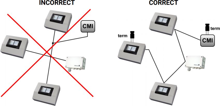
Wiring
A CAN BUS network should never have a star topology. Rather, the correct topology is a line from the
first device (with terminator) to the second, third and so forth. The last bus device has the termina-
tion jumper again.
Example: Connection of three network nodes (NWN) with a 2x2-pole cable and termination of the ter-
minal network nodes (network inside one building)
Each CAN network is to be provided with a 120 ohm BUS terminator at the first and last network sub-
scriber (= termination). This is achieved with a plug-in jumper at the back of the controller. Each CAN
network therefore always has two terminators (one at each end). Branch cables or a star topology
are not permissible for CAN wiring.
19Wireless system (CORA)
Wireless system (CORA)
Principles
The wireless system comprises multiple CORA devices (e.g. CAN-EZ3 and EHS), which communicate
with one another, exchange data or transfer firmware. This functionality cannot fully replace the CAN
bus.
For the wireless system, the CAN-EZ3 has an external antenna. The antenna itself is intended for
mounting outside the meter box. The antenna should not be fitted directly on metal (e.g. meter box).
The wireless range is around 1000 m outdoors, and typically 30 m in buildings (through approx. 2
walls/ceilings, depending on thickness and material). Up to 3 additional wireless devices can be
used as a bridge to enable data to be exchanged under deviating conditions.
A CAN-EZ3 can be paired with maximum 12 CORA devices.
RCV-DL, GBS-F and RAS-F devices cannot be used.
Wireless system settings can be found in the main menu item CORA devices.
Pairing CORA devices
In the ATON set, the included CAN-EZ3A energy meter and the EHS-R immersion heater are already
paired at the factory.
In the main menu, under "CORA devices", a New CORA device is selected.
Once the device type has been selected, additional setting options appear.
Switch to device parameters
Pairing status
Specify CORA ID from target device...
...and select Pair
The target device must have Allow pairing enabled. Information about this can be found in the oper-
ating instructions for the relevant device.
To pair an additional device, navigate back to the Devices menu and create another New device.
If Manual mode is set to ON, the item Output appears under it. Here, you can adjust the set output
for manual mode.
If Connect automatically is set to Yes, when the wireless signal is lost, the system automatically at-
tempts to restore the connection.
20Wireless system (CORA)
Relaying wireless signals
CORA devices can relay signals from other devices. All required settings for this are carried out at
the device, which transmits the signal to be relayed. Pairing with devices that simply relay signals is
not required.
During parameterisation of the CORA device, simply enter the CORA ID of the relaying devices under
the items HOP1-3 (depending on how many relays should occur).
RCV-DL, GBS-F and RAS-F devices cannot be used.
Example: The CORA 1 device should control the CORA 3 wirelessly, but cannot reach it due to the
local conditions. However, CORA 1 can reach CORA 2, and CORA 2 can reach CORA 3.
During parameterisation on CORA 1 (= pairing with CORA 3), the CORA ID
of CORA 3 is entered under CORA ID, and the CORA ID of CORA 2 is en-
tered under HOP1.
No settings are required on CORA 2. This device relays the signals inde-
pendently.
No settings are required on CORA 3 either.
The only change to the pairing process is that CORA IDs are entered under HOP1-3.
To enable additional devices to relay the signal, they should be specified in the corresponding order
under HOP2 and then under HOP3. A data packet is sent by the transmitter to HOP1, HOP2, HOP3
and then to the target device (= "CORA ID"), where defined.
The entry 00000000 means that no relaying will occur.
Deleting a pairing
Under the tab FiD is the item Delete CORA device.
21Wireless system (CORA)
CORA-DL (cable instead of wireless)
From version 1.08, CORA devices can also be connected to the CAN-EZ3 via a cable. This replaces
all functions of the wireless system. A CORA device cannot be run with a wireless and a cabled con-
nection at the same time.
For use with a cable, set "Connection" to CORA-DL in the parameters of
the set CORA device.
Under "CORA ID", enter the ID of the device to be connected. This can usu-
ally be found on a label on the device.
Installation
To use a CORA device via CORA-DL, connect it to the DL bus of the CAN-EZ3.
Devices connected via CORA-DL do not affect the DL bus load.
22Operation
Operation and programming
The CAN-EZ3 is operated via the integral display and the rotary dial and buttons. Programming can
be carried out entirely on the device, but the PC software TAPPS2 is recommended.
Operation of the CAN-EZ3 and menu navigation are described in more detail in the "Operation" in-
structions.
Inputs
The energy meter has 8 inputs for analogue measurements, digital signals (ON/OFF) or pulses.
Type I1 I2 I3 I4 I5 I6 I7 I8
Digital x x x x x x
Analogue (all measured
variables and sensor x x x x
types)
Analogue (measured x x
variable: temp.; sensor: (VT1) (VT2)
FTS)
Pulse
(all measured variables) x x
(e.g. sensor VSG) (DI1)* (DI2)*
S0 signals (max 20 Hz)
Pulse
x x
(measured variable: flow
(VT1)* (VT2)*
rate)
* Important: Connections VT1 and DI1 (= input 7) and VT2 and DI2 (= input 8) cannot be used at the
same time (but use of VT1 and DI2, for example, is possible).
23Default settings Default settings The CAN-EZ3 CAN energy meter is delivered with the following default settings. This programming can of course be supplemented or replaced with your own programming. Overview of TAPPS2 programming Inputs S1 T.heat pump flow Analogue PT1000 S3 T.heat pump rtn Analogue PT1000 S5 Flow rate charging circuit Analogue FTS2-32 DN10 Datalogging The following values are logged in data record "Analogue values"; data record "Digital values" is un- used Datalogging on SD card is deactivated at the factory. 24
Default settings

Functions

The date-specific memory records the values of the heat meter and energy meter, totals them and
stores them in differential mode.
The mathematics function uses output variable Result to offer a display value for the totalled current
output of the heat meter and energy meter.

                                                                                                    25
Functions
Functions
All functions of the UVR16x2 controller are available. You can choose from 43 different functions and
can create up to 128 functions. Functions can also be applied multiple times.
In the following, only those functions are described that are relevant for the actual task of the CAN-
EZ3.
Descriptions of all other functions can be found in the corresponding controller manuals (UVR16x2/
RSM610/UVR610/CAN-I/O45), which can be downloaded from ta.co.at.
Definitions
COP value (COP= Coefficient of Performance)
Ratio of the output heat power (kW) to the consumed electrical operating power incl. auxiliary energy
under test conditions (defined temperature conditions, defined time points).
COP = QWP / Pel
The COP value also includes the power of auxiliary units (thawing energy, fraction of pump capacity
for heating, brine or groundwater heat pumps).
Consequently the COP value is a good criterion for heat pumps.
Test institutes determine this value according to a defined measuring method (DIN EN 255).
However performance number and COP value do not allow any energy-based evaluation of the over-
all system. They are only a snapshot of certain heat pump (HP) type under favourable operating con-
ditions (e.g. at 35°C flow temperature). The (yearly) performance factor is much more meaningful for
a system.
Performance factor β
The performance factor is the actual COP during operation.
It is the ratio of the heat energy yield (kWh) to the consumed operating and auxiliary power kWh) over
a given time period:
β = WUseful / Wel
The more important performance factor for the efficiency of a system is therefore the (annual) per-
formance factor ß.
This is the result of measurements at the electricity meter for the supplied electrical energy (com-
pressor, heat source pump) and at the heat meter (output thermal energy of the heat pump) over a
given time interval. If the interval is one year, then the annual performance factor or annual COP is
referred to.
26Energy manager
Energy manager
Function description
The energy manager manages up to 12 output control functions. The (usually) available surplus
output measured and calculated by the CAN-EZ3 is divided between the output controls involved
due to various parameters and user defined priorities.
Input variables
Enable General enabling of the function (digital value ON/OFF)
Power currently being drawn from the grid
Power from grid • Negative when power is being exported to the grid
• Positive when power is being drawn from the grid
Set value Set value for power drawn from the grid
• The Power from grid input variable is best linked to the system value "Total active power" of
the energy meter used.
• The set value (factory setting: -500 W) makes it possible to prevent power being drawn from
the grid for brief periods (= tolerance value).
Without this kind of tolerance value, a set output level may be specified for the consumer that
cannot be generated by the system (any longer), with the result that power is briefly drawn
from the grid to meet the set output level. By specifying a negative value, power is exported to
the grid instead.
Parameters
No. of involved functions No. of involved output control functions
Click once and then you can specify the involved output control
Involved functions
functions.
Priorities can be assigned here to the output control functions that
are set as involved. When surplus power is available, it is first used
Priority by the output control with priority 1 (= highest priority). The function
with the next highest priority does not become active until the first
function's max. consumer output is reached.
• It is not necessary to establish a link to the output control functions. Instead, the Involved
functions parameter is used.
Output variables
Residual power Amount of available power not used
Power used Amount of available power used
• These output variables are only used for display purposes, e.g. in a function overview. The
consumers are linked to the output variables of the involved output control functions.
27Energy manager Example of a standard diagram Energy manager with output control CAN-EZ3 and EHS(-R) 28
Output control

Output control
Standard diagram
See Energy manager function description.

Function description
The output control function is used to control loads (e.g. EHS immersion heater or LST output con-
troller) according to the specifications of the energy manager function, or by means of forced op-
eration.
When used with an energy manager function, output control is specified in this function's param-
eters as an involved function. Up to 12 output controls can be managed by one energy manager.
For use without an energy manager function, the forced operation and forced operation output
input variables are used. The output can then be specified manually or by any other control event.
With the Participating CORA device parameter, Output control makes it possible to control a de-
vice using the "CORA" wireless system. Further information on this wireless system can be found
in the installation instructions for the corresponding devices.

Input variables
Enable                        General enabling of the function (digital value ON/OFF)
Minimum output
                              Upper and lower limits of the output to be consumed
Maximum output
                              The consumer is not activated until the minimum output + start dif-
                              ferential is reached.
                              The consumer is deactivated again when the output falls below
Start differential
                              minimum output.
                              Operation proceeds, taking account of the minimum runtime, stop
                              delay and blocking time parameters.
                              The consumer is enabled without taking account of the specifica-
Forced operation
                              tions of the energy manager (digital value ON/OFF).
Forced operation output       Set output when forced operation is active.
• When used in conjunction with an energy manager, the set output comes from that function;
  otherwise from the forced operation output input variable.
     • Forced operation takes precedence over the specifications of the energy manager func-
       tion.
• The value of the maximum output input variable should not exceed the maximum output of
  the consumer (e.g. 3 kW for an EHS immersion heater).

                                                                                                   29
Output control
Parameters
Specifies the cycle in which the calculation of the output control
should occur. Delayed responses of consumers can be compen-
Cycle time sated.
This parameter also affects the higher ranking energy manager.
If the consumer is activated, it may only be deactivated again after
Minimum runtime
this time has elapsed.
If the consumer is to be deactivated, it continues to run for this time
Run-on time
until it is actually deactivated.
If the consumer is deactivated, it may only be reactivated after this
Pause time
time has elapsed.
Involved network node (dis- If the function is to control a device via x2 wireless, this is defined
play only for devices with x2 here. A link must first be established with the device in the Network
wireless) node menu.
• Cycle time: If the values of the output control are transmitted, for example, via the CAN bus to a
controller, which switches the consumer, the calculation of the function is much quicker than
values can be transferred via the CAN bus. This can have a negative impact on delayed
responses of the control characteristics (system starts to oscillate). The cycle time should be
matched to the transfer time of the bus.
• The minimum runtime, run-on time and pause time parameters also apply to forced operation.
Output variables
Selection of an analogue output for consumer output modulation
Displays the percentage of modulated output specified for the selected
Correcting variable analogue output (0-100 %)
• 0 % corresponds to 0 W
• 100 % corresponds to the set maximum output
Selection of the switching output of the consumer
Status
Display ON/OFF
Output to be consumed at the moment (specified by the energy man-
Effective set output
ager function)
Minimum runtime
Meter for the remaining minimum runtime (see Parameters)
meter
Run-on time meter Meter for the remaining run-on time (see Parameters)
Pause time meter Meter for the remaining pause time (see Parameters)
Cycle timer Meter for the remaining cycle time (see Parameters)
• The effective set output and the meters are for display only.
Example: Actuation of an EHS-R by PWM
Output control function Connected analogue output
Minimum output parameter 0,05 kW Input value 1 0
Maximum output parameter 3,00 kW Target value 1 10,0 %
Start differential parameter 0,01 kW Input value 2 1000
Target value 2 90,0 %
30Energy meter
Energy meter
Function description
The energy meter takes the analogue value for energy output from other sources (e.g. CAN
energy meter CAN-EZ) and meters the energy according to that value.
Input variables
Enable General enabling of the function (digital value ON/OFF)
Output Analogue value specifying the energy output in kW (to two decimal
places)
Meter reset Digital input signal, ON/OFF, to reset the meter
Price / unit Input of a price per unit (1 kWh)
• When the energy output value is adopted, note that two decimal places must be included.
Example: A dimensionless number 413 will be adopted as 4.13 kW.
• If the energy output values are negative, note that the metering will be negative as well, i.e. the
metered values can also become negative.
• The meter reset is carried out by means of a digital ON pulse or manually from the parameter
menu. It will delete all meter readings, in other words also those from previous periods.
• When the Price / unit is transferred from a source, note that five decimal places must be
included. Example: A dimensionless number without a decimal point such as 413 will be
adopted as 0.00413. If the source is a Fixed value, the unit used should not be a currency
(Euro or Dollar) but rather Dimensionless (.5).
Parameters
Factor Optional: enter an integral factor (a whole number) for the multipli-
cation of the input value
Delete meter reading Pressing this button opens a confirmation prompt, followed by a
reset of all meter readings, including those from previous periods.
31Energy meter Output variables Output The energy output, with the factor applied Day meter reading Prev. day meter reading Week meter reading Prev. week meter reading Month meter reading Meter readings Prev. month meter reading Year meter reading Prev. year meter reading Kilowatt hours total Day sum Previous day sum Week sum Prev. week sum Month sum Display of yield in the set currency Prev. month sum Year sum Prev. year sum Sum total • PLEASE NOTE: The meter readings from the Energy meter function module are saved to the internal memory every hour. Therefore, in the event of a power failure, no more than 1 hour of metering can be lost. • When loading function data, you will be prompted whether you want to apply the saved meter readings (see the Programming Part 1: General information manual). • The changeover of the Week meter occurs on Sundays at 24:00 h. • The meter readings can also be deleted manually in the parameter menu. 32
Heat meter

Heat meter
Standard diagram

Function description
Calculation of thermal output and metering of thermal energy via the temperature differential
T.flow - T.return and the flow rate, and allowing for the antifreeze component in the heat transfer
medium.

Input variables
Enable                        General enabling of the function (digital value ON/OFF)
Flow temperature              Analogue input signal for the flow temperature
Return temperature            Analogue input signal for the return temperature
Flow rate                     Analogue input signal for the flow rate
Meter reset                   Digital pulse input signal, ON/OFF, to reset the meter
Specific heat capacity        Optional: Analogue value specifying the heat capacity of the fluid in
                              the measured system
Price / unit                  A price per kWh for yield calculations
• The BFPT1000 5x60MM sensors fitted in the KH ball valve from Technische Alternative are
  particularly suitable for temperature measurement. The sensors can be removed with little
  effort for the calibration process.
• With a solar thermal system, the collector sensor can also be used as the flow sensor. For that
  to be possible, it must be installed in a sensor well at the flow outlet of the collector header.
  However, the captured amount of heat will then also include the losses in the solar flow line.
• Entering User as the source in the Flow rate input variable allows a fixed value to be entered as
  the flow rate instead the flow rate captured by a flow sensor.
• The meter reset is carried out by a digital ON pulse or manually in the parameter menu. It will
  delete all meter readings, in other words also those from previous periods. The meter will be
  blocked as long as this input variable is set to ON. The meter reset also works when Enable =
  Off.
• Specific heat capacity: This optional specification must be entered as a multiple of the unit
  0.01 kJ/l*K as a dimensionless number. Example: Pure water has a heat capacity of 4.18 kJ/
  l*K at 20 °C, so a dimensionless value of 418 must be entered for this heat capacity (at 20 °C).
  N.B.: The heat capacity of fluids is temperature-dependent. The value entered should there-
  fore be a variable value dependent on the temperature (e.g. from the Curve function).

                                                                                                  33
Heat meter
Parameters
Frost protection Specification of the antifreeze component in %
(shown only if the Spe-
cific heat capacity input
variable is unused)
Reversing lock Available for selection: Yes / No
Status Display: Not calibrated or Calibrated
Calibration value Display of the differential T.flow – T.return measured during the cali-
bration process (in Not calibrated status this value must be 0.0 K)
Start calibration Select to start the calibration process (Note the section Calibration
process!)
Delete calib. values This can be used to undo the calibration. It resets the calibration
value to 0.
Delete meter reading Button for deleting all meter readings
• Antifreeze component (frost protection): An average has been calculated from the product
specifications of all the major manufacturers and tabulated in relation to the mixing ratio.
Under typical conditions this method results in an additional error of no more than one per-
cent.
• Reversing lock: Entering No permits negative metering; entering Yes means that the heat
meter will only be able to meter positive values.
• The tolerance of sensors and measuring device can sometimes lead to substantial errors in
the calculation of the differential temperature. The device has a calibration process to com-
pensate this error.
• After selecting Start calibration, the user is prompted to confirm. If the calibration was per-
formed by mistake or incorrectly, the result can be undone with Delete calib. values and/or
corrected by means of a new calibration.
Calibration process
By simultaneously measuring the same temperature with both sensors, the deviation of the sen-
sors from each other can be ascertained and included as a correction factor in future calcula-
tions.
The calibration affects only the sensor values in the Heat meter function and is not factored into
other functions.
During the calibration process, it is very important that both sensors (flow and return) capture the
same temperatures. This is achieved by binding the two sensor tips together with a piece of tape
or wire. Both sensors should also be fitted now with the lead extensions which will be used later,
so that the electrical resistances of the leads are included. If the collector sensor is being used,
the required lead length should be estimated and integrated. The sensors must be connected to
the two programmed inputs for flow and return and are immersed together in hot water (so that
both are exposed to the same temperature).
Calibration process:
1. Immerse the sensors in the water.
2. Start the calibration process and confirm.
Status display: Calibrated.
3. The calibration values displayed in the parameters and the corrected return temperature is
included in the output variables.
34You can also read