Clarity II Turbidimeter - Turbidity Measurement System
←
→
Page content transcription
If your browser does not render page correctly, please read the page content below
Instruction Manual PN 51T1056/rev.D August 2014 Clarity II™ Turbidimeter Turbidity Measurement System

ESSENTIAL INSTRUCTIONS WARNING
READ THIS PAGE BEFORE PROCEEDING! RISK OF ELECTRICAL SHOCK
Equipment protected throughout by double insulation.
Your instrument purchase from Rosemount
Analytical, Inc. is one of the finest available for your • Installation and servicing of this product may expose personel
particular application. These instruments have been to dangerous voltages.
designed, and tested to meet many national and • Main power wired to separate power source must be
international standards. Experience indicates that its disconnected before servicing.
performance is directly related to the quality of the • Do not operate or energize instrument with case open!
installation and knowledge of the user in operating
and maintaining the instrument. To ensure their con • Signal wiring connected in this box must be rated at least
tinued operation to the design specifications, per 240 V.
sonnel should read this manual thoroughly before • Nonmetallic cable strain reliefs do not provide grounding
proceeding with installation, commissioning, opera between conduit connections! Use grounding type bushings
tion, and maintenance of this instrument. If this and jumper wires.
equipment is used in a manner not specified by the • Unused cable conduit entries must be securely sealed by
manufacturer, the protection provided by it against nonflammable closures to provide enclosure integrity in
hazards may be impaired. compliance with personal safety and environmental protection
requirements. Unused conduit openings must be sealed with
• Failure to follow the proper instructions may
NEMA 4X or IP65 conduit plugs to maintain the ingress
cause any one of the following situations to protection rating (NEMA 4X).
occur: Loss of life; personal injury; property dam
age; damage to this instrument; and warranty • Electrical installation must be in accordance with the National
invalidation. Electrical Code (ANSI/NFPA70) and/or any other applicable
national or local codes.
• Ensure that you have received the correct model
and options from your purchase order. Verify that • Operate only with front panel fastened and in place.
this manual covers your model and options. If • Proper use and configuration is the responsibility of the user.
not, call 18008548257 or 9497578500 to
request correct manual.
• For clarification of instructions, contact your
Rosemount representative.
• Follow all warnings, cautions, and instructions
CAUTION
marked on and supplied with the product.
This product generates, uses, and can radiate radio frequency
• Use only qualified personnel to install, operate, energy and thus can cause radio communication interference.
update, program and maintain the product. Improper installation, or operation, may increase such interfer
• Educate your personnel in the proper installation, ence. As temporarily permitted by regulation, this unit has not
operation, and maintenance of the product. been tested for compliance within the limits of Class A comput
• Install equipment as specified in the Installation ing devices, pursuant to Subpart J of Part 15, of FCC Rules,
section of this manual. Follow appropriate local which are designed to provide reasonable protection against
and national codes. Only connect the product to such interference. Operation of this equipment in a residential
electrical and pressure sources specified in this area may cause interference, in which case the user at his own
manual. expense, will be required to take whatever measures may be
required to correct the interference.
• Use only factory documented components for
repair. Tampering or unauthorized substitution of
parts and procedures can affect the performance
and cause unsafe operation of your process.
• All equipment doors must be closed and protec CAUTION
tive covers must be in place unless qualified per
sonnel are performing maintenance. This product is not intended for use in the light industrial,
residential or commercial environments per the instru
ment’s certification to EN500812.
Emerson Process Management
2400 Barranca Parkway
Irvine, CA 92606 USA
Tel: (949) 7578500
Fax: (949) 4747250
http://www.rosemountanalytical.com
© Rosemount Analytical Inc. 2014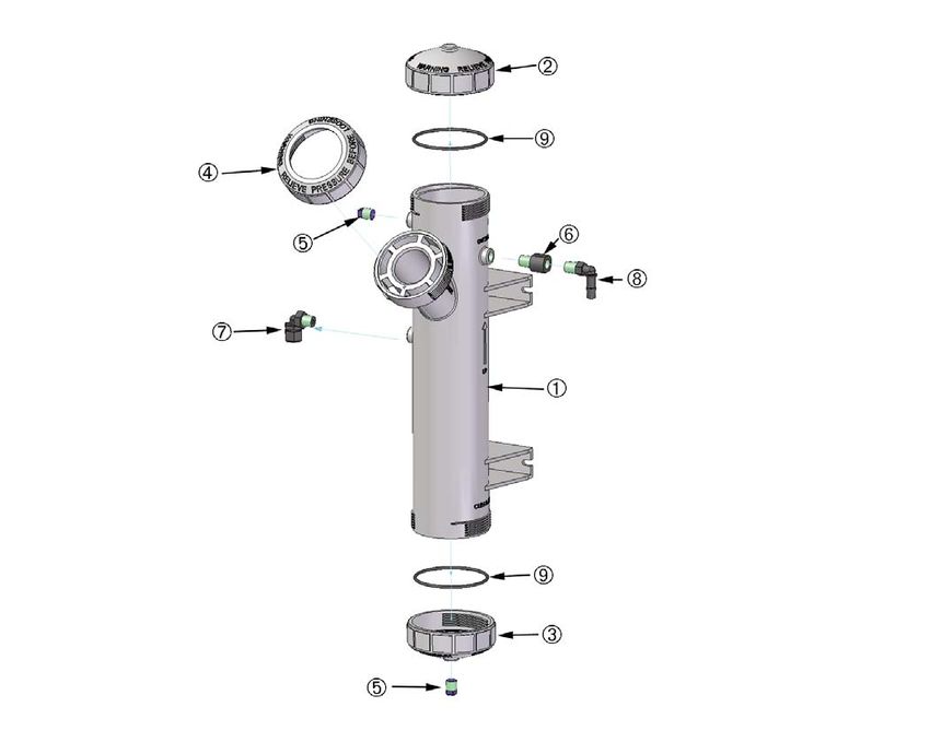
QUICK START GUIDE
FOR CLARITY II TURBIDIMETER
1. Refer to Section 2.0 for installation instructions.
2. The sensor cable is prewired to a plug that inserts into a receiving socket in the analyzer. The cable also passes
through a strain relief fitting. To install the cable…
a. Remove the wrenching nut from the strain relief fitting.
b. Insert the plug through the hole in the bottom of the enclosure nearest the sensor socket. Seat the fitting in the
hole.
c. Slide the wrenching nut over the plug and screw it onto the fitting.
d. Loosen the cable nut so the cable slides easily.
e. Insert the plug into the appropriate receptacle on the circuit board.
f. Adjust the cable slack in the enclosure and tighten the cable nut. For wall/pipe mounting, be sure to leave suffi
cient cable in the enclosure to avoid stress on the cable and connections.
g. Plug the cable into the back of the sensor.
h. Place the sensor in either the measuring chamber or the calibration cup. The sensor must be in a dark place
when power is first applied to the analyzer.
3. Make power, alarm, and output connections as shown in section 3.0 wiring.
4. Once connections are secured and verified, apply power to the analyzer.
5. When the analyzer is powered up for the first time Quick Start screens appear. Follow the Quick Start Guide to
enable live readings.
a. A blinking field shows the position of the cursor.
b. Use the t or u key to move the cursor left or right. Use the p or q key to increase or decrease the value of a
digit. Use the p or q key to move the decimal point.
c. Press ENTER to store a setting. Press EXIT to leave without storing changes. Pressing EXIT also returns the
display to the language selection screen.
IMPORTANT NOTE:
When using EPA/incandescent sensors (PN 801080002EPA):
n DO NOT power up the instrument without the sensor connected
n DO NOT disconnect and reconnect a sensor while an analyzer is powered
If this is inconvenient or cannot be avoided:
1. Cycle power to the instrument after connecting the sensor or..
2. Perform a Slope Calibration or Standard Calibration routine after connecting the sensor. Following these guide
lines will extend the life of the incandescent lamp and avoid premature warnings and faults due to reduced
lamp life.
CONTINUED ON THE FOLLOWING PAGE
QUICK START GUIDE
 Figure A. QUICK START GUIDE, Model 1056
QUICK REFERENCE GUIDE
     Figure B. MODEL 1056 MENU TREE
About This Document
This manual contains instructions for installation and operation of the Clarity II Model
T1056 Turbidimeter.
The following list provides notes concerning all revisions of this document.
Rev. Level Date Notes
A 12/07 This is the initiallaunch version.
B 2/09 Update Specifications
C 12/09 Update DNV logo, company name
D 08/14 Change turbidity specifications, add CSA Nonincendive field
wiring installation drawings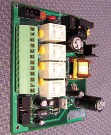
MODEL CLARITY II TABLE OF CONTENTS
MODEL CLARITY II TURBIDIMETER
TABLE OF CONTENTS
Section Title Page
1.0 DESCRIPTION AND SPECIFICATIONS .............................................................................. 1
1.1 Features and Applications ...................................................................................................... 1
1.2 Specifications ......................................................................................................................... 2
2.0 INSTALLATION...................................................................................................................... 5
2.1 Unpacking and Inspection ...................................................................................................... 5
2.2 Installation ............................................................................................................................. 5
2.3 Installation — Debubbler Assembly........................................................................................ 8
2.4 Installation — Sensor ............................................................................................................. 10
2.5 Sample Point .......................................................................................................................... 10
3.0 WIRING .................................................................................................................................. 13
3.1 General................................................................................................................................... 13
3.2 Preparing Conduit Openings ................................................................................................. 13
3.3 Preparing Sensor Cable ......................................................................................................... 14
3.4 Power, Output, and Sensor Connections ............................................................................... 14
4.0 DISPLAY AND OPERATION ................................................................................................. 19
4.1 User Interface......................................................................................................................... 19
4.2 Instrument Keypad ................................................................................................................. 19
4.3 Main Display........................................................................................................................... 20
4.4 Menu System ......................................................................................................................... 21
5.0 PROGRAMMING THE ANALYZER ....................................................................................... 23
5.1 General................................................................................................................................... 23
5.2 Changing StartUp Settings ..................................................................................................... 23
5.3 Configuring and Ranging the Current Outputs ....................................................................... 23
5.4 Setting a Security Code.......................................................................................................... 25
5.5 Security Access ...................................................................................................................... 26
5.6 Using Hold.............................................................................................................................. 26
5.7 Resetting Factory Default Settings......................................................................................... 27
5.8 Programming Alarm Relays.................................................................................................... 28
6.0 PROGRAMMING TURBIDITY ............................................................................................... 31
6.1 Programming Measurements Introduction ........................................................................... 31
6.2 Turbidity Measurement Programming .................................................................................... 32
6.3 Choosing Turbidity or Total Suspended solids ....................................................................... 35
6.4 Entering a Turbidity to TSS Conversion Equation .................................................................. 38
7.0 CALIBRATION ....................................................................................................................... 41
7.1 Calibration Introduction .......................................................................................................... 41
7.2 Turbidity Calibration................................................................................................................ 41
8.0 MAINTENANCE .................................................................................................................... 45
8.1 Model 1056............................................................................................................................. 45
8.2 Sensor .................................................................................................................................... 46
8.3 Debubbler and Measuring Chamber ...................................................................................... 47
8.4 List of Replacement Parts ...................................................................................................... 48
9.0 TROUBLESHOOTING........................................................................................................... 49
9.1 Overview ................................................................................................................................ 49
9.2 Troubleshooting Using Fault Codes ....................................................................................... 45
9.3 Troubleshooting Calibration Problems ................................................................................... 47
9.4 Troubleshooting Other Problems............................................................................................ 52
10.0 RETURN OF MATERIAL ...................................................................................................... 55
10.1 General................................................................................................................................... 56
10.2 Warranty Repair ..................................................................................................................... 57
10.3 NONWarranty Repair ............................................................................................................ 57
i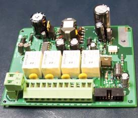
MODEL CLARITY II TABLE OF CONTENTS
LIST OF FIGURES
Number Title Page
21 Panel Mount Dimensions ......................................................................................... 6
22 Pipe and Wall Mount Dimensions............................................................................. 7
23 Debubbler and Flow Chamber ................................................................................. 9
24 Sensor .................................................................................................... 10
25 Sampling for Turbidity............................................................................................... 10
26 CSA Nonincendive Field Wiring Installation for Turbidity, page 1............................ 11
27 CSA Nonincendive Field Wiring Installation for Turbidity, page 2............................ 12
31 24VDC Power Supply............................................................................................... 14
32 Switching AC Power Supply ..................................................................................... 14
33 Current Output Wiring .............................................................................................. 15
34 Alarm Relay Wiring................................................................................................... 15
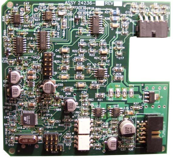
35 Turbidity Signal Board .............................................................................................. 16
36 Power Wiring for Model 1056 85265 VAC Power Supply ....................................... 17
37 Power Wiring for Model 1056 24VDC Power Supply ............................................... 17
38 Output Wiring for Model 1056 Main PCB ................................................................. 18
41 Formatting the Main Display..................................................................................... 22
52 Configuring and Ranging the Current Outputs ........................................................ 24
53 Setting a Security Code............................................................................................ 25
54 Using Hold................................................................................................................ 26
55 Resetting Factory Default Settings........................................................................... 27
61 Converting Turbidity to TSS ..................................................................................... 33
64 Turbidity Sensor — General ..................................................................................... 35
65 Turbidity Sensor — EPA 108.1 ................................................................................. 35
66 Turbidity Sensor — ISO 7027................................................................................... 36
62 Converting Turbidity to TSS ..................................................................................... 38
62 Lowest Turbidity (TSS) ............................................................................................. 38
67 Configure Turbidity Measurement ............................................................................ 40
78 Calibrate Turbidity .................................................................................................... 44
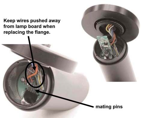
83 Replacing the Lamp/LED Board............................................................................... 46
84 Molded Buffer Assembly........................................................................................... 48
LIST OF TABLES
Number Title Page
21 Approximate Debubbler Pressure as a Function of Flow ........................................ 8
611 Turbidity Measurement Programming ...................................................................... 32
712 Turbidity Calibration Routines ..................................................................................... 41
81 Replacement Parts for Model 1506 .......................................................................... 45
APPENDIX
APPENDIX .............................................................................................................. 56
ii
MODEL CLARITY II SECTION 1.0
DESCRIPTION AND SPECIFICATIONS
SECTION 1.0.
DESCRIPTION AND SPECIFICATIONS
• COMPLETE SYSTEM includes single or dual input analyzer, sensor(s), and debubbler
assembly
• CHOOSE U.S. EPA METHOD 180.1 or ISO METHOD 7027 compliant sensors
• RESOLUTION 0.001 NTU
• FULL FEATURED ANALYZER with fully scalable analog outputs and fully programmable
alarms with interval timers
• INTUITIVE, USERFRIENDLY MENU in seven languages makes setup and calibration
easy
Clarity II is a trademark of Emerson Process Management.
1.1 FEATURES AND APPLICATIONS
The Clarity II turbidimeter is intended for the determi The Clarity II turbidimeter incorporates the popular
nation of turbidity in water. Low stray light, high stability, and easy to use Model 1056 analyzer. Menu flows
efficient bubble rejection, and a display resolution of and prompts are so intuitive that a manual is practically
0.001 NTU make Clarity II ideal for monitoring the not needed. Analog outputs are fully scalable. Alarms
turbidity of filtered drinking water. The Clarity II are fully programmable for high/low logic and dead
turbidimeter can be used in applications other than band. To simplify programming, the analyzer automati
drinking water treatment. Examples are monitoring cally detects whether an EPA 180.1 or ISO 7027
wastewater discharges, condensate returns, and clarifiers. sensor is being used.
Both USEPA 180.1 and ISO 7027compliant sensors Clarity II is available in an optional configuration in
are available. USEPA 180.1 sensors use a visible light which the analyzer, sensor(s), and debubbling flow
source. ISO 7027 sensors use a near infrared LED. cell(s) are mounted on a single back plate. The sensor
For regulatory monitoring in the United States, USEPA cables are prewired to the analyzer, so setup is
180.1 sensors must be used. Regulatory agencies in exceptionally fast and easy. All the user does is mount
other countries may have different requirements. the unit on a wall, bring in power and sample, and pro
vide a drain. To order this option, consult the factory.
The Clarity II turbidimeter consists of an analyzer,
which accepts either one or two sensors, the sensors
themselves, and a debubbler/measuring chamber and
cable for each sensor. The cable plugs into the sensor
and the analyzer, making setup fast and easy. Sensors
can be located as far as 50 ft (15.2 m) away from the
analyzer.
1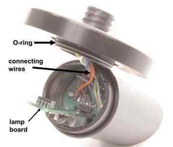
MODEL CLARITY II SECTION 1.0
DESCRIPTION AND SPECIFICATIONS
SPECIFICATIONS General Power: Code 02: 20 to 30 VDC. 15 W.
Enclosure: Polycarbonate. Type 4X/CSA 4 (IP65). Code 03: 85 to 265 VAC, 47.5 to 65.0 Hz, switching.
Dimensions: Overall 155 x 155 x 131mm (6.10 x 6.10 15 W.
x 5.15 in.). Cutout: 1/2 DIN 139mm x 139mm (5.45 x Note: Code 02 and 03 power supplies include 4 pro
grammable relays
5.45 in.)
Equipment protected by double insulation
RFI/EMI: EN61326
LVD: EN610101
Alarms relays*: Four alarm relays for process meas
urement(s) or temperature. Any relay can be config
ured as a fault alarm instead of a process alarm. Each
relay can be configured independently and each can
be programmed with interval timer settings.
Relays: Form C, SPDT, epoxy sealed
Maximum Relay Current
Conduit Openings: Accepts 1/2” or PG13.5 conduit Resistive
fittings 28 VDC 5.0 A
Display: Monochromatic graphic liquid crystal display. 115 VAC 5.0 A
128 x 96 pixel display resolution. Backlit. Active
230 VAC 5.0 A
display area: 58 x 78mm (2.3 x 3.0 in.).
Ambient Temperature and Humidity: 0 to 55°C Inductive load: 1/8 HP motor (max.), 40 VAC
(32 to 131°F). Turbidity only: 0 to 50°C (32 to
122°F), RH 5 to 95% (noncondensing) CAUTION
Storage Temperature Effect: 20 to 60ºC (4 to 140°F) RISK OF ELECTRICAL SHOCK
Hazardous Location Approvals *Relays only available with 02 power supply (20 30 VDC) or 03
Options for CSA: 02, 03, 20, 21, 22, 24, 25, 26, 27, 30, switching power supply (85 265 VAC)
31, 32, 34, 35, 36, 37, 38, AN, and HT.
Class I, Division 2, Groups A, B, C, & D WARNING
WARNING
Class Il, Division 2, Groups E, F, & G
Class Ill T4A Tamb= 50° C Exposure to some chemicals may degrade the
sealing properties used in the following devices:
Evaluated to the ANSI/UL Standards. The ‘C’ and ‘US’ indi
cators adjacent to the CSA Mark signify that the product has Zettler Relays (K1K4) PN AZ81CH12DSEA
been evaluated to the applicable CSA and ANSI/UL
Standards, for use in Canada and the U.S. respectively Inputs: One or two isolated sensor inputs
POLLUTION DEGREE 2: Normally only nonconductive Outputs: Two 420 mA or 020 mA isolated current out
pollution occurs. Occasionally, however, a temporary puts. Fully scalable. Max Load: 550 Ohm. Output 1
conductivity caused by condensation must be expected. has superimposed HART signal (configurations
Altitude: for use up to 2000 meter (6562 ft.) 10560X2X3XHT only)
Current Output Accuracy: ±0.05 mA @ 25 ºC
Terminal Connections Rating: Power connector
(3leads): 2412 AWG wire size. Signal board ter
minal blocks: 2616 AWG wire size. Current output
connectors (2leads): 2416 AWG wire size. Alarm
relay terminal blocks: 2412 AWG wire size
(02 24 VDC power supply and 03 85265VAC
power supply)
2MODEL CLARITY II SECTION 1.0
DESCRIPTION AND SPECIFICATIONS
SPECIFICATIONS — SENSOR
Method: EPA 180.1 or ISO 7027 (using 860 nm LED
source). Must be specified when ordering.
Incandescent lamp life: two years
LED life: five years
Wetted materials: Delrin1, glass, EPDM
Accuracy after calibration at 20.0 NTU:
0 1 NTU: ±2% of reading or ±0.015 NTU,
whichever is greater.
0 20 NTU: ±2% of reading
Note: Turbidity values of 2200 NTU can be meas
ured, but frequent cleaning may be required to main
tain turbidity measurements.
Cable: 20 ft (6.1 m) or 50 ft (15.2 m). Maximum 50 ft
(15.2 m). Connector is IP65.
Maximum Pressure: 30 psig (308 kPa abs)
Temperature: 40 95°F (5 35°C)
Sensor body rating: IP65 when cable is connected
SPECIFICATIONS — DEBUBBLER AND
FLOW CHAMBER
Dimensions: 18.1 in. x 4.1 in. diam. (460 mm x 104 mm
diam.) (approx.)
Wetted materials: ABS, EPDM, Delrin1, polypropylene,
nylon
Inlet: compression fitting accepts 1/4 in. OD tubing; fit
ting can be removed to provide 1/4 in. FNPT
Drain: barbed fitting accepts 3/8 in. ID tubing; fitting can
be removed to provide 1/4 in. FNPT. Must drain to
atmosphere.
Sample temperature: 40 95°F (5 35°C)
Minimum inlet pressure : 3.5 psig (125 kPa abs). 3.5
psig will provide about 250 mL/min sample flow.
Maximum inlet pressure: 30 psig (308 kPa abs). Do
not block drain tube.
Recommended sample flow: 250 750 mL/min
Response Time: The table shows the time in minutes to
percent of final value following a step change in turbid
ity.
1Delrin is a registered trademark of DuPont Performance
Elastomers.
SPECIFICATIONS — MISCELLANEOUS
Weight/shipping weight:
Sensor: 1 lb/2 lb (0.5 kg/1.0 kg)
Analyzer: 2 lb/3 lb (1.0 kg/1.5 kg)
Debubbler: 3 lb/4 lb (1.5 kg/2.0 kg)
(rounded to the nearest lb or 0.5 kg
3This page left blank intentionally. 4
MODEL CLARITY II SECTION 2.0
INSTALLATION
SECTION 2.0.
INSTALLATION
2.1 UNPACKING AND INSPECTION
2.2 INSTALLATION
2.1 UNPACKING AND INSPECTION
The Clarity II Turbidimeter is a complete system for the determination of turbidity in drinking water. The system
consists of the analyzer, sensor(s), cable(s), and flow chamber/debubbler(s). Consult the table to verify that you
have received the parts for the option you ordered.
Item Model/part number
Single Input Turbidity Analyzer 1056032738AN
Dual Input Turbidity Analyzer 1056032737AN
Single Input Turbidity Analyzer with HART 1056032738HT
Dual Input Turbidity Analyzer with HART 1056032737HT
SensorEPA standard 801080002EPA
SensorISO standard 801080003ISO
Cable3 ft (0.9 m) 2413800
Cable20 ft (6.1 m) 2409700
Cable50 ft (15.2 m) 2409800
Calibration cup 2410100
Molded chamber/debubbler 2417000
(1) The analyzer model number is printed on a label attached to the side of the instrument.
2.2 INSTALLATION
2.2.1 General Information
1. Although the analyzer is suitable for outdoor use, do not install it in direct sunlight or in areas of extreme
temperatures.
2. Install the analyzer in an area where vibration and electromagnetic and radio frequency interference are
minimized or absent.
3. Keep the analyzer and sensor wiring at least one foot from high voltage conductors. Be sure there is easy
access to the analyzer.
4. The analyzer is suitable for panel, pipe, or surface mounting. Refer to the table below.
Type of Mounting Figure
Panel 21
Wall and Pipe 22
WARNING
WARNING
RISK OF ELECTRICAL SHOCK
Electrical installation must be in accordance with the
National Electrical Code (ANSI/NFPA70) and/or any
other applicable national or local codes.
5FIGURE 21 PANEL MOUNTING DIMENSIONS
MILLIMETER
INCH
126.4
5.0
17.13
1.1 101.6
4.00
154.9
6.1
154.9
6.1
Front View
Side View
( 126.4
5.0 )
76.2
3.0
41.4
1.6
Bottom View
152.73
6.0
Note: Panel mounting seal integrity (4/4X) for outdoor applications is the responsibility of the end user.
6FIGURE 22 PIPE AND WALL MOUNTING DIMENSIONS
(Mounting bracket PN:2382000)
MILLIMETER
INCH
154.9 Wall / Surface Mount
6.1
232
9.1
102
4.0 33.5
1.3
130
5.1
187 154.9 165
7.4 6.1 6.5
Side View
Front View
Pipe Mount
232
Bottom View 9.1
33.5
1.3
130
5.1
80.01
3.2
165
6.5
45.21
1.8
108.9
4.3
Side View
71.37
2.8
The front panel is hinged at the bottom. The panel swings down for easy access to the wiring locations.
7MODEL CLARITY II SECTION 2.0
INSTALLATION
2.3 INSTALLATION — DEBUBBLER ASSEMBLY
See Figure 23 for installation.
Connect the sample line to the inlet fitting. The fitting accepts 1/4inch OD tubing. See Section 2.6 for recom
mended installation of the sample port.
Attach a piece of 3/8 inch ID soft tubing to the drain fitting. The debubbler must drain to atmosphere.
NOTE
During operation, the debubbler is under pressure. A 0.040 inch (1 mm) orifice in the outlet pro
vides the pressure. Back pressure helps prevent outgassing, which can lead to bubbles accu
mulating on the sensor face resulting in erroneous readings. DO NOT EXCEED 30 psig (308
kPa abs) inlet pressure.
WARNING
Before removing the sensor, be absolutely certain
that the process pressure is reduced to 0 psig and
the process temperature is lowered to a safe level!
The amount of pressure in the debubbler can be estimated from the flow rate. See Table 21.
To control and monitor sample flow, a valved rotameter with fittings is available (PN 2410300). Attach the
rotameter to the debubbler outlet. The rotameter can also be used to increase back pressure on the debubbler if
additional pressure is needed to prevent outgassing.
TABLE 21. Approximate debubbler pressure
as a function of flow (0.040 inch outlet orifice)
gph psig mL/min kPa abs
2 1 100 110
4 3 200 120
6 8 300 140
8 14 400 160
10 21 500 190
11 26 600 240
12 31 700 280
— — 800 340
8MODEL CLARITY II SECTION 2.0
INSTALLATION
INCH
MILLIMETER
FIGURE 23. Debubbler and Flow Chamber
9MODEL CLARITY II SECTION 2.0
INSTALLATION
2.4 INSTALLATION — SENSOR
Unscrew the nut on the side of the debubbler. Insert the sensor in the mouth of the measuring chamber. Be sure
the pin on the debubbler lines up with the hole in the sensor. Replace the nut. Remove the protective cap from
the sensor and screw the cable onto the receptacle. The plug and receptacle are keyed for proper alignment.
The sensor is rated to IP65 when properly connected to the cable. To prevent possible water damage to the
connector contacts, be sure the cable receptacle and the connector on the back of the sensor are dry when
connecting or disconnecting the cable.
INCH
MILLIMETER
DWG. NO. REV.
40T105501 A
FIGURE 24. Sensor
2.5 SAMPLE POINT
Locate the sample tap to minimize pickup of sediment or air. See Figure 25. If possible, install a sampling port
that extends one or two inches (25 50 mm) into the pipe. Use ¼ inch OD rigid plastic tubing. Avoid soft plastic
tubing if possible. To reduce sample lag time, install the debubbler and flow chamber as close to the sample tap
as possible.
FIGURE 25. Sampling for Turbidity
10D 0000 SEE ECO BJ
D1
! WARNING
METAL CONDUIT FOR USE WITH NON-FLAMMABLE
PROCESS MEDIA ONLY
SENSOR CABLE 5 6
IS SHIELDED
POWER SUPPLY 3
CLARITY II
TURBIDITY
ANALOG OUTPUT SENSOR #2
D2 (OPTIONAL)
METAL CONDUIT
CLARITY II
TURBIDITY
ALARM SENSOR #1
METAL CONDUIT WIRING (VAC)
(OPTIONAL)
UNCLASSIFIED 1056-27/37 SENSOR CABLE 5 6
HAZARDOUS AREA IS SHIELDED
AREA
CLASS I, DIV. 2, GPS A-D, 0° - 50 ° C THIS DOCUMENT IS
CERTIFIED BY
CLASS II, III, DIV 2, GPS E-G UNCLASSIFIED CSA REV C
REV
AREA REV
5 MAX CABLE LENGTH IS 50 FEET. REV
REV
REV
4 DURING INSTALLATION, LEAVE MAXIMUM AMOUNT OF JACKET INSULATION POSSIBLE ON N.I. FIELD REVISIONS NOT PERMITTED
D3 W/O AGENCY APPROVAL
WIRING WITHIN INSTRUMENT ENCLOSURE. AFTER TERMINATION, WRAP N.I. FIELD WIRING WITHIN
ENCLOSURE WITH MYLAR TAPE, TO ENSURE ADEQUATE DOUBLE INSULATION REMAINS.
DIMENSIONS ARE IN INCHES Emerson
APPROVALS DATE ROSEMOUNT
REMOVE BURRS & SHARP EDGES
PROCESS MANAGEMENT ANALYTICAL
3 GROUND CONNECTION MAY BE MADE IN HAZARDOUS AREA. MACHINE FILLET RADII .020 MAX
NOMINAL SURFACE FINISH: 125 DRAWN B. JOHNSON 12/8/04 TITLE
ANGLES ± 1/2°. NON INCENDIVE FIELD
2. SEAL REQUIRED AT EACH CONDUIT ENTRANCE. .XX ± .03 .XXX ± .010 CHECKED J. FLOCK 1/5/05
MATERIAL
WIRING INSTALLATION (CSA)
ENG APVD J. FLOCK 1/5/05 1056-27/37
1. INSTALLATION MUST CONFORM TO THE CEC. SIZE DWG NO REV
FINISH THIS FILE CREATED USING
SOLID EDGE C 1400314 D
NOTES: UNLESS OTHERWISE SPECIFIED SCALE: NONE WEIGHT: SHEET 1 OF 1
Figure 26
1112
Figure 27MODEL CLARITY II SECTION 3.0
WIRING
SECTION 3.0.
WIRING
3.1 GENERAL
3.2 PREPARING CONDUIT OPENINGS
3.3 PREPARING SENSOR CABLE
3.4 POWER, OUTPUT, AND SENSOR
CONNECTIONS
3.1 GENERAL
The 1056 is easy to wire. It includes removable connectors and slideout signal input boards.
3.1.1. Removable connectors and signal input boards
Model 1056 uses removable signal input boards and communication boards for ease of wiring and instal
lation. Each of the signal input boards can be partially or completely removed from the enclosure for wiring.
The Model 1056 has three slots for placement of up to two signal input boards and one communication
board. Slot 1Left Slot 2 – Center Slot 3 – Right
Comm. board Input Board 1 Input Board 2
3.1.2. Signal Input boards
Slots 2 and 3 are for signal input measurement boards. Wire the sensor leads to the measurement board
following the lead locations marked on the board. After wiring the sensor leads to the signal board, carefully slide
the wired board fully into the enclosure slot and take up the excess sensor cable through the cable gland. Tighten
the cable gland nut to secure the cable and ensure a sealed enclosure.
3.1.3. Digital Communication boards
HART and Profibus DP communication boards will be available in the future as options for Model 1056 digital
communication with a host. The HART board supports Bell 202 digital communications over an analog
420mA current output. Profibus DP is an open communications protocol which operates over a dedicated
digital line to the host.
3.1.4 Alarm relays
Four alarm relays are supplied with the switching power supply (85 to 265VAC, 03 order code) and the 24VDC
power supply (2030VDC, 02 order code). All relays can be used for process measurement(s) or temperature.
Any relay can be configured as a fault alarm instead of a process alarm. Each relay can be configured
independently and each can be programmed as an interval timer, typically used to activate pumps or control
valves. As process alarms, alarm logic (high or low activation or USP*) and deadband are userprogrammable.
Customerdefined failsafe operation is supported as a programmable menu function to allow all relays to be
energized or notenergized as a default condition upon powering the analyzer.
The USP* alarm can be programmed to activate when the conductivity is within a userselectable
percentage of the limit. USP alarming is available only when a contacting conductivity measurement board is
installed.
3.2 PREPARING CONDUIT OPENINGS
There are six conduit openings in all configurations of Model 1056. (Note that four of the openings will be fitted
with plugs upon shipment.)
Conduit openings accept 1/2inch conduit fittings or PG13.5 cable glands. To keep the case watertight, block
unused openings with Type 4X or IP65 conduit plugs.
NOTE: Use watertight fittings and hubs that comply with your requirements. Connect the conduit hub to the
conduit before attaching the fitting to the analyzer.
13MODEL CLARITY II SECTION 3.0
WIRING
3.3 PREPARING SENSOR CABLE
The Model 1056 is intended for use with all Rosemount Analytical sensors. Refer to the sensor installation instructions
for details on preparing sensor cables.
3.4 POWER, OUTPUT, AND SENSOR CONNECTIONS
3.4.1 Power wiring
Two Power Supplies are offered for Model T1056:
a. 24VDC (20 – 30V) Power Supply (02 ordering code)
b. 85 – 265 VAC Switching Power Supply (03 ordering code)
AC mains (115 or 230V) leads and 24VDC leads are wired to the Power Supply board which is mounted vertically
on the left side of the main enclosure cavity. Each lead location is clearly marked on the Power Supply board.
Wire the power leads to the Power Supply board using the lead markings on the board.
24VDC Power Supply (02 ordering code) is shown below:
This power supply automatically
detects DC power and accepts 20VDC
to 30VDC inputs.
Four programmable alarm relays are
included.
Figure 31
Switching AC Power Supply (03 ordering code) is shown below:
This power supply automatically
detects AC line conditions and switches
to the proper line voltage and line
frequency.
Four programmable alarm relays are
included.
Figure 32
14MODEL CLARITY II SECTION 3.0
WIRING
3.4.2 Current Output wiring Keep sensor and output signal wiring separate from
All instruments are shipped with two 420mA current power wiring. Do not run sensor and power wiring in the
outputs. Wiring locations for the outputs are on the same conduit or close together in a cable tray.
Main board which is mounted on the hinged door of the
instrument. Wire the out put leads to the correct posi
tion on the Main board using the lead markings (+/positive,
/negative) on the board. Male mating connectors are
provided with each unit.
For best EMI/RFI protection use shielded output signal
cable enclosed in an earthgrounded metal conduit.
Connect the shield to earth ground. AC wiring should
be 14 gauge or greater. Provide a switch or breaker to
disconnect the analyzer from the main power supply.
Install the switch or breaker near the analyzer and label Figure 3.3
it as the disconnecting device for the analyzer.
3.4.3 Alarm relay wiring
Four alarm relays are supplied with the switching power supply (85 to 265VAC, 03 order code) and the 24VDC
power supply (2030VDC, 02 order code). Wire the relay leads on each of the independent relays to the correct
position on the power supply board using the printed lead markings (NO/Normally Open, NC/Normally Closed, or
Com/Common) on the board. See Fig 33.
NO1
COM1 RELAY 1
NC1
NO2
COM2 RELAY 2
NC2
NO3
COM3 RELAY 3
NC3
NO4
COM4 RELAY 4
NC4
Figure 34 Alarm Relay Wiring for Model 1056 Switching Power Supply (03 Order Code)
3.4.4 Sensor wiring to signal boards
Plug the preterminated sensor cable connector directly into the turbidity signal board mating connector.
WARNING
WARNING
RISK OF ELECTRICAL SHOCK
Electrical installation must be in accordance with the
National Electrical Code (ANSI/NFPA70) and/or any
other applicable national or local codes.
15MODEL CLARITY II SECTION 3.0
WIRING
3.2.2 Sensor
The sensor cable is prewired to a plug that inserts into a receiving socket on the signal board. See Figures 31.
The cable also passes through a strain relief fitting. To install the cable…
1. Remove the wrenching nut from the strain relief fitting.
2. Insert the plug through the hole in the bottom of the enclosure nearest the sensor socket. Seat the fitting in the
hole.
3. Slide the wrenching nut over the cable plug and screw it onto the fitting.
4. Loosen the cable nut so the cable slides easily.
5. Insert the plug into the appropriate receptacle. To remove the plug, squeeze the release clip and pull straight
out.
6. Adjust the cable slack in the enclosure and tighten the cable nut. Be sure to allow sufficient slack to avoid plac
ing stress on the cable and connections.
7. Plug the cable into the back of the sensor. The sensor is rated to IP65 when properly connected to the cable.
To prevent possible water damage to the connector contacts, be sure the cable receptacle and the connec
tor on the back of the sensor are dry when connecting or disconnecting the cable.
8. Place the sensor in either the measuring chamber or the calibration cup. The sensor must be in a dark place
when power is first appled to the analyzer.
Note: If “S1 Warning” appears, check sensor cable connection and confirm sample water flow at debubbler
drain outlet.
Figure 35 Turbidity signal board with plugin Sensor connection
IMPORTANT NOTE:
When using EPA/incandescent sensors (PN 801080002EPA):
n DO NOT power up the instrument without the sensor connected
n DO NOT disconnect and reconnect a sensor while an analyzer is powered
If this is inconvenient or cannot be avoided:
3. Cycle power to the instrument after connecting the sensor or...
4. Perform a Slope Calibration or Standard Calibration routine after connecting the sensor.
Following these guidelines will extend the life of the incandescent lamp and avoid premature warnings and faults
due to reduced lamp life.
16MODEL CLARITY II SECTION 3.0
WIRING
FIGURE 36 Power Wiring for Model 1056 85265 VAC Power Supply (03 ordering code)
To Main PCB
FIGURE 37 Power Wiring for Model 1056 24VDC Power Supply (02 ordering code)
17MODEL CLARITY II SECTION 3.0
WIRING
FIGURE 38 Output Wiring for Model 1056 Main PCB
18MODEL CLARITY II SECTION 4.0
DISPLAY AND OPERATION
SECTION 4.0
DISPLAY AND OPERATION
4.1 USER INTERFACE
4.2 KEYPAD
4.3 MAIN DISPLAY
4.4 MENU SYSTEM
4.1 USER INTERFACE
The Model 1056 has a large display which shows two
live measurement readouts in large digits and up to four
additional process variables or diagnostic parameters
concurrently. The display is backlit and the format can
be customized to meet user requirements. The intuitive
menu system allows access to Calibration, Hold (of cur
rent outputs), Programming, and Display functions by
pressing the MENU button. In addition, a dedicated
DIAGNOSTIC button is available to provide access to
useful operational information on installed sensor(s)
and any problematic conditions that might occur. The
display flashes Fault and/or Warning when these condi
tions occur. Help screens are displayed for most fault
and warning conditions to guide the user in trou
bleshooting.
During calibration and programming, key presses cause
different displays to appear. The displays are self
explanatory and guide the user stepbystep through
the procedure.
4.2 INSTRUMENT KEYPAD
There are 4 Function keys and 4 Selection keys on the
instrument keypad.
Function keys:
The MENU key is used to access menus for program
ming and calibrating the instrument. Four toplevel
menu items appear when pressing the MENU key:
Calibrate: calibrate attached sensors and
analog outputs.
Hold: Suspend current outputs.
Program: Program outputs, measurement,
temperature, security and reset.
Display: Program display format, language,
warnings, and contrast
Pressing MENU always causes the main menu screen
to appear. Pressing MENU followed by EXIT causes
the main display to appear.
19MODEL CLARITY II SECTION 4.0
DISPLAY AND OPERATION
Pressing the DIAG key displays active Faults and Offset, selected measurement range, Cable
Warnings, and provides detailed instrument information Resistance, Temperature Sensor Resistance, Signal
and sensor diagnostics including: Faults, Warnings, Board software version.
Sensor 1 and 2 information, Out 1 and Out 2 live current
values, model configuration string e.g. 1056012031 The ENTER key. Pressing ENTER stores numbers and
AN, Instrument Software version, and AC frequency settings and moves the display to the next screen.
used. Pressing ENTER on Sensor 1 or Sensor 2 pro
vides useful diagnostics and information (as applica The EXIT key. Pressing EXIT returns to the previous
ble): Measurement, Sensor Type, Raw signal value, screen without storing changes.
Cell constant, Zero Offset, Temperature, Temperature
Selection keys:
Surrounding the ENTER key, four Selection keys – up,
down, right and left, move the cursor to all areas of the
screen while using the menus.
Selection keys are used to:
1. select items on the menu screens
2. scroll up and down the menu lists.
3. enter or edit numeric values.
4. move the cursor to the right or left
5. select measurement units during operations
4.3 MAIN DISPLAY
The Model 1056 displays one or two primary measurement
values, up to four secondary measurement values, a
fault and warning banner, alarm relay flags, and a
digital communications icon.
Process measurements:
Two process variables are displayed if two signal boards are installed. One process variable and process tem
perature is displayed if one signal board is installed with one sensor. The Upper display area shows the Sensor
1 process reading. The Center display area shows the Sensor 2 process reading.
For single input configurations, the Upper display area Displayable Secondary Values
shows the live process variable.
Slope 1 Man Temp 2
Secondary values: Ref Off 1 Output 1 mA
Up to four secondary values are shown in four display Gl Imp 1 Output 2 mA
quadrants at the bottom half of the screen. All four
secondary value positions can be programmed by the Ref Imp 1 Output 1 %
user to any display parameter available. Possible Raw Output 2 %
secondary values include:
mV Input Measure 1
Temp 1 Blank
Man Temp 1
20MODEL CLARITY II SECTION 4.0
DISPLAY AND OPERATION
Fault and Warning banner:
If the analyzer detects a problem with itself or the sensor the word Fault or Warning will appear at the bottom of
the display. A fault requires immediate attention. A warning indicates a problematic condition or an impending fail
ure. For troubleshooting assitance, press Diag.
Formatting the Main Display
The main display screen can be programmed to show primary process variables, secondary process variables and
diagnostics.
1. Press MENU
2. Scroll down to Display. Press ENTER.
3. Main Format will be highlighted. Press ENTER.
4. The sensor 1 process value will be highlighted in reverse video. Press the selection keys to navigate down
to the screen sections that you wish to program. Press ENTER.
5. Choose the desired display parameter or diagnostic for each of the four display sections in the lower screen.
6. Continue to navigate and program all desired screen sections. Press MENU and EXIT. The screen will
return to the main display.
For single sensor configurations, the default display shows the live process measurement in the upper display area
and temperature in the center display area. The user can elect to disable the display of temperature in the cen
ter display area using the Main Format function. See Fig. 41 to guide you through programming the main display
to select process parameters and diagnostics of your choice.
For dual sensor configurations, the default display shows Sensor 1 live process measurement in the upper display
area and Sensor 2 live process measurement temperature in the center display area. See Fig. 41 to guide you
through programming the main display to select process parameters and diagnostics of your choice.
4.4 MENU SYSTEM
Model 1056 uses a scroll and select menu system.
Pressing the MENU key at any time opens the toplevel
menu including Calibrate, Hold, Program and Display
functions.
To find a menu item, scroll with the up and down keys
until the item is highlighted. Continue to scroll and
select menu items until the desired function is chosen.
To select the item, press ENTER. To return to a previ
ous menu level or to enable the main live display,
press the EXIT key repeatedly. To return immediately
to the main display from any menu level, simply press
MENU then EXIT.
The selection keys have the following functions:
The Up key (above ENTER) increments numerical values, moves the decimal place one place to the right,
or selects units of measurement.
The Down key (below ENTER) decrements numerical values, moves the decimal place one place to the
left, or selects units of measurement
The Left key (left of ENTER) moves the cursor to the left.
The Right key (right of ENTER) moves the cursor to the right.
To access desired menu functions, use the “Quick Reference” Figure B. During all menu displays (except main
display format and Quick Start), the live process measurements and secondary measurement values are
displayed in the top two lines of the Upper display area. This conveniently allows display of the live values during
important calibration and programming operations.
Menu screens will time out after two minutes and return to the main live display.
21MODEL CLARITY II SECTION 4.0
DISPLAY AND OPERATION
FIGURE 41 Formatting the Main Display
22MODEL CLARITY II SECTION 5.0
PROGRAMMING THE ANALYZER BASICS
SECTION 5.0.
PROGRAMMING THE ANALYZER BASICS
5.1 GENERAL
5.2 CHANGING STARTUP SETTINGS
5.3 CONFIGURING AND RANGING 420MA OUTPUTS
5.4 SETTING SECURITY CODES
5.5 SECURITY ACCESS
5.6 USING HOLD
5.7 RESETTING FACTORY DEFAULTS – RESET ANALYZER
5.8 PROGRAMMING ALARM RELAYS
5.1 GENERAL
Section 5.0 describes the following programming functions:
Changing the measurement type, measurement units and temperature units.
Configure and assign values to the current outputs
Set a security code for two levels of security access
Accessing menu functions using a security code
Enabling and disabling Hold mode for current outputs
Resetting all factory defaults, calibration data only, or current output settings only
5.2 CHANGING STARTUP SETTINGS
5.2.1 Purpose
To change the measurement type, measurement units, or temperature units that were initially entered in Quick
Start, choose the Reset analyzer function (Sec. 5.7) or access the Program menus for sensor 1 or sensor 2 (Sec.
6.0). The following choices for specific measurement type, measurement units are available for each sensor meas
urement board.
5.2.2 Procedure.
Follow the Reset Analyzer procedure (Sec 5.7) to reconfigure the analyzer to display new measurements or
measurement units. To change the specific measurement or measurement units for each signal board type,
refer to the Program menu for the appropriate measurement (Sec. 6.0).
5.3 CONFIGURING AND RANGING THE CURRENT OUTPUTS
5.3.1 Purpose The low and high current outputs can be set to any
The Model 1056 accepts inputs from two sensors and value.
has two analog current outputs. Ranging the outputs 2. ASSIGNING OUTPUTS. Assign a measurement to
means assigning values to the low (0 or 4 mA) and high Output 1 or Output 2.
(20 mA) outputs. This section provides a guide for 3. DAMPEN. Output dampening smooths out noisy
configuring and ranging the outputs. ALWAYS readings. It also increases the response time of the
CONFIGURE THE OUTPUTS FIRST. output. Output dampening does not affect the
response time of the display.
5.3.2 Definitions 4. MODE. The current output can be made directly
1. CURRENT OUTPUTS. The analyzer provides a con proportional to the displayed value (linear mode) or
tinuous output current (420 mA or 020 mA) directly directly proportional to the common logarithm of the
proportional to the process variable or temperature. displayed value (log mode).
23MODEL CLARITY II SECTION 5.0
PROGRAMMING THE ANALYZER BASICS
5.3.3. Procedure: Configure Outputs. S1: 1.234µS/cm 25.0ºC
Under the Program/Outputs menu, the adjacent screen S2: 12.34pH 25.0ºC
will appear to allow configuration of the outputs. Follow OutputM Configure
the menu screens in Fig. 52 to configure the outputs. Assign: S1 Meas
Range: 420mA
Scale: Linear
Dampening: 0sec
Fault Mode: Fixed
Fault Value: 21.00mA
5.3.4. Procedure: Assigning Measurements the Low S1: 1.234µS/cm 25.0ºC
and High Current Outputs S2: 12.34pH 25.0ºC
The adjacent screen will appear when entering the OutputM Assign
Assign function under Program/Output/Configure. S1 Measurement
These screens allow you to assign a measurement, S2 Measurement
process value, or temperature input to each output.
Follow the menu screens in Fig. 52 to assign
measurements to the outputs.
5.3.5. Procedure: Ranging the Current Outputs S1: 1.234µS/cm 25.0ºC
The adjacent screen will appear under S2: 12.34pH 25.0ºC
Program/Output/Range. Enter a value for 4mA and Output Range
20mA (or 0mA and 20mA) for each output. Follow the OM SN 4mA: 0.000µS/cm
menu screens in Fig. 52 to assign values to the out OM SN 20mA: 20.00µS/cm
puts. OM SN 4mA: 00.00pH
OM SN 20mA: 14.00pH
Figure 52. Configuring and Ranging the Current Outputs
24MODEL CLARITY II SECTION 5.0
PROGRAMMING THE ANALYZER BASICS
5.4 SETTING A SECURITY CODE 2. Scroll down to Security. Select Security.
3. The security entry screen appears. Enter a
5.4.1 Purpose. three digit security code for each of the desired
The security codes prevent accidental or unwanted security levels. The security code takes effect
changes to program settings, displays, and calibration. two minutes after the last key stroke. Record
Model 1056 has two levels of security code to control the security code(s) for future access and
access and use of the instrument to different types of communication to operators or technicians as
users. The two levels of security are: needed.
All: This is the Supervisory security level. It
allows access to all menu functions, including 4. The display returns to the security menu
Programming, Calibration, Hold and Display. screen. Press EXIT to return to the previous
Calibration/Hold: This is the operator or screen. To return to the main display, press
technician level menu. It allows access to MENU followed by EXIT.
only calibration and Hold of the current outputs.
Fig. 53 displays the security code screens.
5.4.2 Procedure.
1. Press MENU. The main menu screen appears.
Choose Program.
Figure 53. Setting a Security Code
MAIN MENU
S1: 1.234µS/cm 25.0ºC
Program
S2: 12.34pH 25.0ºC
Program
Outputs
Measurement
Temperature
S1: 1.234µS/cm 25.0ºC
S2: 12.34pH 25.0ºC
Security
Security
Calibration/Hold: 000
Diagnostic Setup All: 000
Ambient AC Power:Unk
Reset Analyzer
25MODEL CLARITY II SECTION 5.0
PROGRAMMING THE ANALYZER BASICS
5.5 SECURITY ACCESS 5.6 USING HOLD
5.5.1 How the Security Code Works 5.6.1 Purpose
When entering the correct access code for the The analyzer output is always proportional to measured
Calibration/Hold security level, the Calibration and value. To prevent improper operation of systems or
Hold menus are accessible. This allows operators or pumps that are controlled directly by the current
technicians to perform routine maintenance. This output, place the analyzer in hold before removing
security level does not allow access to the Program or the sensor for calibration and maintenance. Be sure
Display menus. to remove the analyzer from hold once calibration is
When entering the correct access code for All security complete. During hold, both outputs remain at the last
level, the user has access to all menu functions, includ value. Once in hold, all current outputs remain on
ing Programming, Calibration, Hold and Display. Hold indefinitely.
5.5.2 Procedure. 5.6.2 Using the Hold Function
1. If a security code has been programmed, selecting To hold the outputs,
the Calibrate, Hold, Program or Display top menu 1. Press MENU. The main menu screen appears.
items causes the security access screen to appear Choose Hold.
2. The Hold Outputs and Alarms? screen
2. Enter the threedigit security code for the appropriate appears. Choose Yes to place the analyzer in
security level. hold. Choose No to take the analyzer out of
S1: 1.234µS/cm 25.0ºC hold.
S2: 12.34pH 25.0ºC Note: There are no alarm relays with this con
Security Code figuration. Current outputs are included with all
000 configurations.
3. The Hold screen will then appear and Hold
will remain on indefinitely until Hold is
3. If the entry is correct, the appropriate menu screen disabled.
appears. If the entry is incorrect, the Invalid Code
screen appears. The Enter Security Code screen See figure 51 below.
reappears after 2 seconds.
Figure 54. Using Hold
MAIN MENU
S1: 1.234µS/cm 25.0ºC
S1: 1.234µS/cm 25.0ºC
Hold
S2: 12.34pH 25.0ºC
S2: 12.34pH 25.0ºC
Hold S1 Hold outputs
S1 Hold: No and alarms?
No
S2 Hold: No
Yes
26You can also read