Cephalopod-Inspired Miniaturized Suction Cups for Smart Medical Skin
←
→
Page content transcription
If your browser does not render page correctly, please read the page content below
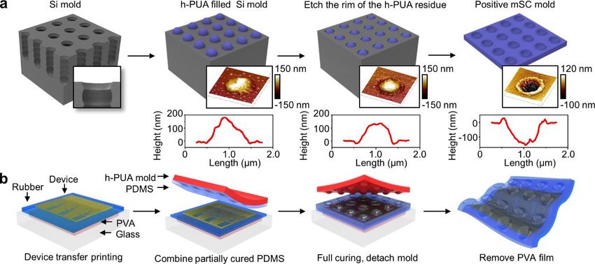
www.advhealthmat.de
www.MaterialsViews.com

Cephalopod-Inspired Miniaturized Suction Cups for Smart

 COMMUNICATION
Medical Skin
Moon Kee Choi, Ok Kyu Park, Changsoon Choi, Shutao Qiao, Roozbeh Ghaffari,
Jaemin Kim, Dong Jun Lee, Myungbin Kim, Wonji Hyun, Seok Joo Kim, Hye Jin Hwang,
Seung-Hae Kwon, Taeghwan Hyeon, Nanshu Lu, and Dae-Hyeong Kim*

Nature has inspired important advances in the design of conformal adhesion without chemical adhesives.[24,25] Here, we
mechanical/chemical adhesives.[1–5] In particular, recent dem- present cephalopod-inspired miniaturized suction cup (mSC)
onstrations of biomimetic dry adhesives based on gecko setae[6–9] dry adhesives that are combined with ultrathin stretchable elec-
and chemical glues derived from shellfish proteins[10] provide tronics to create a new class of glue-free diagnosis and therapy
compelling routes for medical devices that must interface with system. The ultralow modulus (≈108 kPa) mSC array sup-
skin and/or organs. The intimate interfacing is important,[11,12] ports embedded stretchable electronics and drug-loaded thera-
since it oftentimes determines the wearability[13,14] and the peutic nanoparticles, while firmly laminating on skin without
quality of diagnosis and therapy.[15–20] Capabilities for the mul- inducing skin irritations/damages during long-term usage and
tiple regeneration of adhesives and the biocompatibility upon removal. The integrated system allows continuous monitoring
detachment from target skin/organ surfaces require more of vital sign changes in various physiologic or pathophysiologic
advanced technologies. However, robust, conformal contacts conditions, controllable release of drugs, and wireless commu-
between medical electronics/therapeutics and curvilinear, tex- nication from/to external devices for the remote healthcare.
tured surfaces of dynamically contorting skin remain chal- Strong van der Waals forces and negative pressure based on
lenging with existing packaged electronics and encapsulation mSC structures create robust mechanical coupling with skin,
strategies.[21–23] which enables highly sensitive/accurate biometric sensing and
 Cephalopods (e.g., octopus and squid) provide an intriguing effective transdermal drug delivery, while preserving the tacki-
example in nature, whereby the arrayed geometry of suc- ness over many uses and drug reloading. These new adhesion
tion cups and low modulus of the skin achieve robust and features serve a powerful, low cost alternative to single use
 chemical adhesives.
 A representative scenario in clinical applications is described
M. K. Choi, C. Choi, J. Kim, D. J. Lee, M. Kim, in Figure 1, whereby the electronic patch is firmly laminated
W. Hyun, S. J. Kim, Prof. T. Hyeon, Prof. D.-H. Kim
Center for Nanoparticle Research
 on skin and linked to a wrist band that contains a power
Institute for Basic Science (IBS) supply, a controller, and short-range wireless data transmis-
Seoul 151-742, Republic of Korea sion unit (Figures S1–S3, Supporting Information). The mSCs
E-mail: dkim98@snu.ac.kr (Figure 1c; atomic force microscopy (AFM) images) inspired
M. K. Choi, C. Choi, J. Kim, D. J. Lee, M. Kim, by octopus tentacles (Figure 1b and inset; optic (left) and 3D
W. Hyun, S. J. Kim, Prof. T. Hyeon, Prof. D.-H. Kim laser scanner (right) image) generate negative pressure, which
School of Chemical and Biological Engineering
Institute of Chemical Processes promote adherence to skin. The ultrathin form factor (
www.advhealthmat.de
 www.MaterialsViews.com
COMMUNICATION

 Figure 1. Overview of the electronic patch with bioinspired dry adhesives. a) Schematic illustration of the multifunctional miniaturized suction cup
 (mSC) electronic patch. Vital signs are monitored by electrodes, strain gauges, and temperature sensors. Drugs loaded in the mesoporous silica nano-
 particles are transdermally delivered by iontophoresis. The mSC structures are located at the interface between the patch and skin as dry adhesives.
 The smart band (connected to the mSC patch) provides wireless functionalities and a power source. b) Photograph of the cephalopod tentacle (left;
 inset shows the entire octopus) and 3D laser scanning image of magnified suction cup (right). c) 3D AFM image of mSC array (left) and magnified
 view (right). The dimension is submicrometer and system modulus is ≈108 kPa. d) Schematic illustration of the wireless communication system.
 Short distance wireless network (Bluetooth) and power supply units are included in the custom-made smart band. Vital signs are transferred to smart
 devices through Bluetooth and transmitted to remote healthcare centers through RF communication units. e) Control of transdermal drug delivery
 rates wirelessly via iontophoresis. f) The electronic patch is reused after cleaning (inset) and drug reloading.

 reloaded periodically on the electronic patch (Figure 1f). This thinner than the rest of the system (≈45 µm), thereby allowing
 system offers a range of possibilities for mobile, point-of-care the electronic patch with mSC arrays to achieve the ultralow
 medical services. system modulus (≈108 kPa), which is smaller than the modulus
 The fabrication process for the low modulus electronic of epidermis (≈150 kPa), as shown in Figure S5 (Supporting
 patch in combination with the aforementioned mSC struc- Information). These fabrication steps are completed upon full
 tures is described in Figure S4b (Supporting Information). cure and removal from the mold. Dissolution of the temporary
 First, the stretchable electronics (Figure S1, Supporting Infor- PVA film finally allows lamination of the electronic patch on
 mation) are transferred onto ultrathin rubber (≈14 µm and skin (Figure S2, Supporting Information).
 ≈39 kPa) coated on the poly(vinylalcohol) (PVA) film. The Figure 2a shows scanning electron microscope (SEM)
 hard-poly(urethane acrylate) (h-PUA) mold with intaglio mSC images of the cephalopod-inspired mSC (top) and the gecko-
 patterns with super-hydrophobic coating is separately prepared inspired miniaturized pillar (m-pillar; bottom) structures. Inset
 (Figure S4a, Supporting Information). The mold is sequentially shows the top view of mSC structures. These two bioinspired
 spin-casted with diluted polydimethylsiloxane (PDMS) layers, structures are used to evaluate the tackiness of dry adhesives.
 whose modulus is gradually altered from ≈1.6 MPa to ≈500 kPa Although m-pillars enhance adhesion strength by increasing
 (Figure S5a–d, Supporting Information). The relatively high surface area, these structures require relatively high modulus
 modulus (≈1.6 MPa) layer helps to form mSC structures, while materials to maintain their shape without leaning, bending
 the low modulus (≈500 kPa) layer provides a soft interfacial or collapsing.[26] The system modulus of m-pillar structures
 layer.[26] The thickness of coated PDMS layers (≈4 µm) is much (≈1.4 MPa; Figure S5e,f, Supporting Information) is thus

 2 wileyonlinelibrary.com © 2015 WILEY-VCH Verlag GmbH & Co. KGaA, Weinheim Adv. Healthcare Mater. 2015,
 DOI: 10.1002/adhm.201500285
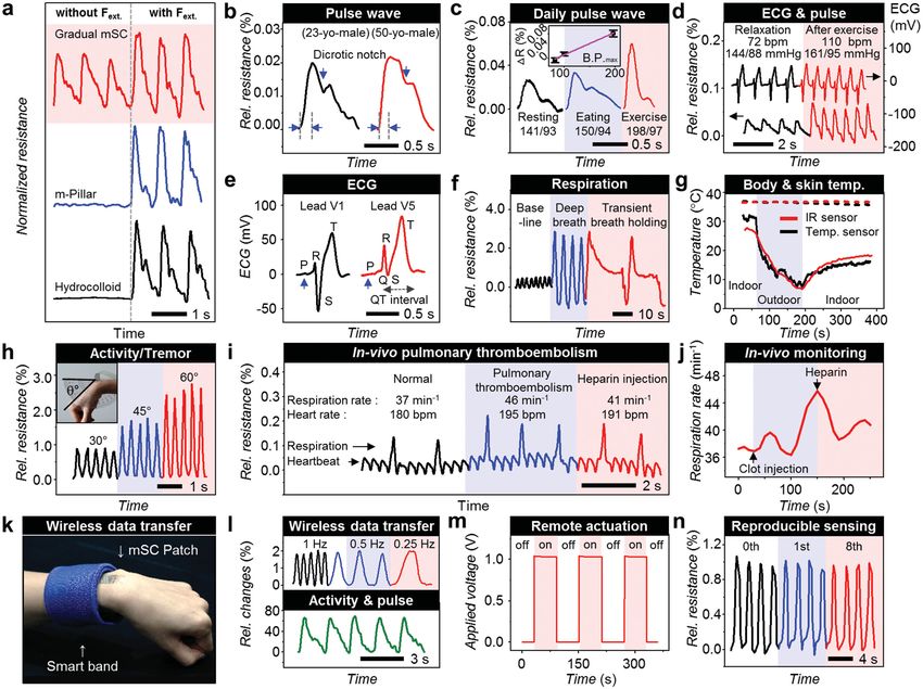
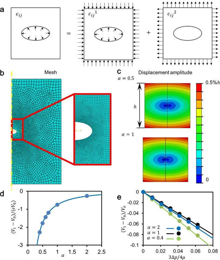
www.advhealthmat.de
www.MaterialsViews.com

 COMMUNICATION
Figure 2. Bioinspired suction cups as comfortable dry adhesives. a) SEM images of the side view of mSCs (top; inset shows top-view of mSCs) and
m-pillars (bottom). b) Change in adhesion force on the skin topology mold with different surface-structured patches (flat, m-pillars, and mSCs with
different moduli). c) Confocal microscope images (cross-section and 3D view) at the vicinity of the contacting interface between structured patch and
skin mold (left: m-pillar and right: gradual mSC). d) Spheroidal void embedded in the infinite body with Lame constants (µ, λ) and semiaxes (a1, a2,
a3) = (a, a, αa). The initial pressure and volume of the void (p0, V0) are changed to (p1, V1) when compressive strain ε is applied. After removing the
load, the void would partially recover its shape to (p2, V2). e) The max (Δp/p0ε) versus α. The α* is computed to be 0.32 with dimension of mSCs
(a1 = 500 nm and a3 = 160 nm). f) Durability tests of mSC patches on the back of mice in comparisons to flat, m-pillar, and commercial hydrocolloid
patch. g) Scratching behavior test compared with hydrocolloid patch. h) Load on patch-attached skin when extra strain is applied. i) Change in the
adhesion strength during recycling of mSC and hydrocolloid patch on the skin. j) Skin morphologies after three times of delaminating hydrocolloid
patch (left) and mSC patch (right).

higher than that of the epidermis. In contrast, the mSCs with denotes atmospheric pressure. Applying a compressive strain of
low aspect ratio (≈150 nm height and ≈950 nm diameter) can be ε on top of the patch will squeeze some air out of the mSCs,
readily fabricated with ultralow system modulus (≈108 kPa) and giving rise to new volume V1, while pressure remains the same,
exhibit greater tackiness (Figure 2b) by a factor of ≈ 3 relative to i.e., p1 = p0. When ε is removed, assuming no air can come back
m-pillars. Increased adhesion force comes from the conformally to the mSC, the mSC volume will partially recover and the final
contacted skin-interface and suction effect of mSC structures. pressure and volume becomes p2 and V2. Since V2 > V1, we
Confocal microscope images provide more information about expect p2 < p0, assuming the amount of gas in the mSC remains
enhanced adhesion forces and conformal contacts of mSCs the same. Therefore, removal of ε effectively creates a negative
over m-pillars on highly variable skin morphologies (Figure 2c). pressure of Δp = p0 − p2 inside the mSC, and a resulting suction
 The mechanics underlying enhanced adhesion of mSCs are force.
analyzed theoretically by finite element modeling (FEM) (Sup- To analytically solve nondimensionalized Δp/(p0ε) as a
porting Information). Assuming that the mSCs are compressed function of a, b, and n, where a = a3/a1, b = p0/m, and m and
against a frictionless surface, due to symmetry, a 2D array of n represent the shear modulus and Poisson's ratio of the
mSCs on the surface of half space is equivalent to a 2D array matrix, respectively, we implement the following strategy
of spheroids in an infinite body, where the Eshelby’s inhomo- (see Supporting Information Appendix for details). First, we use
geneity solution applies.[27] Due to this symmetry of the struc- Eshelby’s inhomogeneity solution to analytically derive V1(V0, ε).
ture as well as loading conditions, the Eshelby’s solution can be Applying negative pressure Δp to a relaxed mSC allows calcu-
applied to the current system. As the stress field in Eshelby’s lation of the final volume V2(V0, Δp). The ideal gas equation
problem decays with distance cubed, i.e., proportional to 1/r3, p0V1(V0,ε) = p2V2(V0, p0–p2) becomes an equation with just
an mSC structure with radius of 500 nm, spacing of 4 mm, one unknown variable, p2, which is analytically solvable. Since
and patch thickness of 47 mm justifies negligible neighboring Eshelby's solution is only valid for small deformation, we
effects and the half space assumption. Therefore, the 2D array have implemented the following constraints on our solution:
of spheroids can be simplified into a single spheroid model 0 ≤ ε ≤ 5% and 0 ≤ (V0 −V1)/V0 ≤ 10%. Practically, it is also
with an eighth of it depicted in Figure 2d, with the semiaxes required that 0 ≤ p2 ≤ p0. The analytical solution under these
of the spheroid being (a1, a2, a3) = (a, a, αa). The initial pres- constraints is plotted in Figure 2e, with b = 2.8 (p0 = 101 kPa,
sure and volume of the mSC are given by p0 and V0, where p0 m = 36 kPa) and n = 0.499 fixed. As shown in Figure 2e, the

Adv. Healthcare Mater. 2015, © 2015 WILEY-VCH Verlag GmbH & Co. KGaA, Weinheim wileyonlinelibrary.com 3
DOI: 10.1002/adhm.201500285
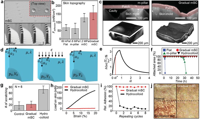
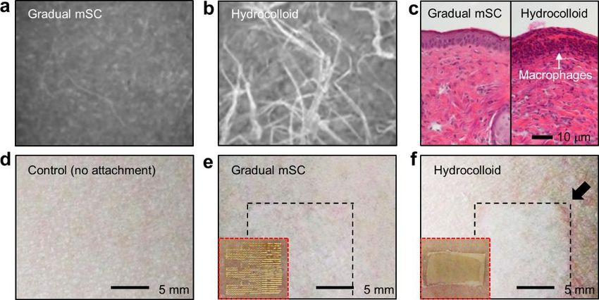
www.advhealthmat.de
 www.MaterialsViews.com

 maximum allowable Δp/p0 first increases and then decreases
COMMUNICATION

 in the Hematoxylin and eosin (H&E) histological stains, which
 with α, suggesting an optimum α can be found with the given show the presence of macrophages and other inflammatory
 constraints. Experimentally, α* is computed to be 0.32 with a1 = cells near the dermis for the hydrocolloid patch (Figure S7c,
 500 nm and a3 = 160 nm, which is highlighted in Figure 2e. In Supporting Information). The mSC did not exhibit any inflam-
 addition to mSC shape, material properties including m and n matory responses and biocompatibility was confirmed in the
 can also affect max(Δp/p0). human wearability experiment, in which the mSC patch was
 Wearable patches often cause time-dependent irritation and laminated on human arms for 4 d (Figure S7d–f, Supporting
 discomfort.[28] To quantify the effects of wear on the skin, we Information).
 designed animal model studies to assess behaviors in response Conformal integration of ultrathin electronic sensors
 to patch wear. We monitored mice fitted with these wearable onboard mSC smart skin establishes a tight skin-interfaced
 patches and used a video camera to monitor their behaviors platform for vital sign monitoring with high sensitivity. For
 in cages (Figure S6a,b, Supporting Information). A detailed example, strain gauges (Figure S8a,b, Supporting Information)
 description of the experiment to observe animal behavior is integrated on mSC patch have high sensitivity to precisely detect
 included in Supporting Information. Briefly, electronic patches an arterial pulse wave from the radial artery of a healthy subject
 are laminated on the back skin of each mouse. We recorded the (Figure S9a, Supporting Information) without the external pres-
 number of scratches over 3 h to assess the degree of irritation. sure (Figure 3a, top). In contrast, strain gauges on the m-pillar
 To evaluate long-term wearability, we compared the durability and hydrocolloid patches cannot detect slight changes of small
 of mSCs patches relative to m-pillar/flat patches and commer- arterial pulse without external pressure (Figure 3a, middle and
 cial hydrocolloid patches by affixing patches to the lower back bottom).[26,30] Arterial pulse signals noninvasively measured
 surface of mice. The mSCs and hydrocolloid patches firmly by the mSC electronic patch are sufficiently accurate to obtain
 adhered on mice skin for over 2 d, whereas the m-pillar and flat clinically important information on cardiovascular aging, i.e., to
 patches delaminated in 2 and 30 h, respectively, due to weaker distinguish the dicrotic notch (a tiny dig between systolic and
 adhesion and mechanical interaction with skin (Figure 2f). diastolic phase in the arterial pressure waveform) and the slope
 Therefore we excluded m-pillar and flat patches then com- of the pulse (Figure 3b). With aging or the increase of arterial
 pared the degree of the comfort of the mSC patches with stiffness, the dicrotic notch in the arterial waveform becomes
 commercial hydrocolloid patches that show good adhesion less pronounced and the slope is steeper.[31] Figure 3b shows
 by relying on chemical adhesives. The number of scratches a representative example of a mSC electronics-measured arte-
 recorded with mSC patches is similar to the control (mice with rial waveform with distinct dicrotic notch and less steep slope
 bare back), while the number of scratches counted with com- in a young subject (a 23-year-old male) when compared with
 mercial hydrocolloid patches is four times higher (Figure 2g). that with less prominent notch and steep slope in an old sub-
 The difference in shear forces applied to the skin (Figure 2h) ject (a 50-year-old male). The peak values of arterial pulse waves
 explains scratching tendencies. The higher stiffness of the com- obtained from mSCs during daily activity of resting, eating, and
 mercial hydrocolloid patches induces the higher loads/strains exercise (Figure 3c) are linearly correlated with systolic blood
 on the skin, which in turn give rise to high skin discomfort, pressure measured by a commercial blood pressure gauge at
 while vice versa in the mSC patches. This behavior analysis the identical time, suggesting the potential function as a blood
 agrees with FEM simulations (Figure S6e,f, Supporting Infor- pressure monitor (inset of Figure 3c).
 mation). See Figure S6c-l (Supporting Information) for more Moreover, the real-time ECGs are simultaneously measured
 details about the relation between the patch stiffness and with integrated electrodes, as shown in Figure 3d (detailed
 scratch count. numbers are indicated at the top). Effective adhesiveness of
 Another important aspect of electronic patches is the reusa- mSCs to the skin enables to monitor the pulse and ECG con-
 bility.[29] The mSC patch maintains its adhesion strength for ≈8 sistently without drift or distortion during exercise as well as
 cycles of reuse, whereas the hydrocolloid patch loses its adhe- resting state (Figure 3d). Since ultraconformal lamination of
 sion force significantly after the first use, causing detachment mSC electronics on the epidermis remarkably reduces far-field
 from the skin (Figure 2i) and thereby difficulty to reuse elec- noises, subtle change of electrical signals originating from the
 tronics. This reusing of smart medical skin enables refreshing heart can be detected with high sensitivity, allowing distinct
 the skin surface in the long-term use. Figure 2j shows skin con- discrimination of a P-wave with small amplitude of ≈2.5 mV,
 ditions following three attachment/detachment cycles over the a QRS complex, and a T-wave in ECGs (Figure 3e). It helps to
 course of 1 d (dry adhesives in mSC patch and chemical adhe- differentiate various cardiac arrhythmic diseases, most of which
 sives in hydrocolloid patch). The top half of the frame shows are diagnosed from accurate detection of a P-QRS-T-wave.
 bare skin without patch while the bottom half shows a skin The measurement of chest wall movement provides res-
 segment under the patch. Black dotted lines show the border piratory information under various conditions, as shown in
 between two segments. The skin laminated with a hydrocolloid Figure 3f. The skin temperature changes indoor (warm) and
 patch (left) undergoes some amount of abrasion and scarring outdoor (cold) are also monitored using temperature sensors
 that is visually observed, while skin in contact with the mSC on human arms (Figure S8c,d, Supporting Information), which
 patch (right) remains intact. Fluffs are also peeled off by the are exactly matched with commercial IR camera measurement
 hydrocolloid patch in the regions of skin with rashes and scar- (Figure 3g). Body temperature can be measured by positioning
 ring (compare images of Figure S7a,b, Supporting Informa- mSC patch on the axillary area, possibly providing important
 tion). Moreover, skin segments underneath the hydrocolloid medical information on fever or hypothermia manifested in
 patches exhibited an inflammatory response. This is evident various diseases. In addition to vital signs, physical activities

 4 wileyonlinelibrary.com © 2015 WILEY-VCH Verlag GmbH & Co. KGaA, Weinheim Adv. Healthcare Mater. 2015,
 DOI: 10.1002/adhm.201500285
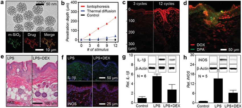
www.advhealthmat.de
www.MaterialsViews.com

 COMMUNICATION
Figure 3. Measurement of vital signs, detection of acute medical conditions, and wireless communications. a) Pulse waves measured on the radial
artery with/without external pressure. Only mSC patch can record pulse waves without pressurization. b) Comparison of an arterial pulse waveform
between the different age groups (23-year-old male and 50-year-old male). c) Changes of arterial pulse waves during daily activity. The peak intensity
correlates linearly with the systolic blood pressure (inset). d) Variation in vital signs due to exercises (top: ECG signals from electrodes, bottom: pulse
signals from Si strain gauges). e) Surface ECGs recorded on the chest. The electrical waveforms of a P-QRS-T complex are reproduced from the V1
and V5 sites, respectively. f) Change in relative resistance at various respiration patterns including baseline, deep breath, and transient breath holding.
g) Variance in the body (dashed line) and skin (line) temperature under indoors and outdoors. h) Movement signals as changing angles of joint motion.
Inset shows the image of measuring strain. i,j) Variation in respiration and heartbeats in a mouse model of acute pulmonary thromboembolism induced
by intravenous injection of massive blood clots and treated with heparin (i). Change in respiration rate at whole time range (j). k) Image of wireless
communication settings. The mSCs patch is connected with the smart band which involves the Bluetooth unit and the battery. l) Tremor and pulse
data wirelessly received from the Bluetooth system. m) Remotely controlled voltage to turn iontophoresis on/off for the transdermal drug delivery.
n) Tested strain gauge functionality after eight times recycling.

are quantified by characterizing the joint movement frequency skin-coupled mSC electronic patches. In the massive pulmo-
with angular changes (Figure 3h and Figure S9b,c, Supporting nary thromboembolism models, sudden elevation of respira-
Information). With the help of mSC structures, the smart tory and heart rates are alarmed and recovered by immediate
skin achieves tight coupling on the skin even under dynamic intravenous infusion of 50 µg heparin (Figure 3i,j). In the
motions. Tremor caused by physiologic or pathophysiologic animal experimental models of acute hypothermia induced by
conditions including Parkinson’s disease can also be monitored ethanol tap on the body, body temperature, heart rate, and res-
(Figure S9d, Supporting Information). piratory rate are monitored by its simultaneous multirecording
 Continuous monitoring of vital sign changes with mSCs system. The early detection of slow heart rate and depressed
can help detect acute medical conditions,[32] thereby facili- respiration with low body temperature following hypothermia
tating medical assists through wireless connections to emer- facilitates the rapid treatment such as warming (Figure S10a,b,
gency clinical service providers. In animal experimental models Supporting Information). In the norepinephrine-induced
(Balb/c nude mouse) of acute medical conditions including hypertensive models, heart rates are abruptly elevated and sta-
hypothermia, hypertensive emergency, and massive pulmo- bilized with the subsequent administration of 100 µg propran-
nary thromboembolism, vital signs are monitored in vivo with olol (Figure S10c,d, Supporting Information).

Adv. Healthcare Mater. 2015, © 2015 WILEY-VCH Verlag GmbH & Co. KGaA, Weinheim wileyonlinelibrary.com 5
DOI: 10.1002/adhm.201500285
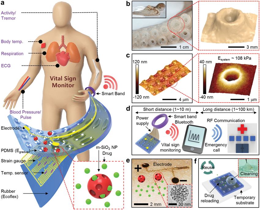
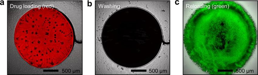
www.advhealthmat.de
 www.MaterialsViews.com
COMMUNICATION

 Figure 3k–m shows wireless data transmission and con- The multifunctional mSC electronic patch allows highly sen-
 trolled drug release through the Bluetooth unit of the custom- sitive monitoring of vital signs for long time, detection of acute
 made smart band (Figure S3, Supporting Information) in con- medical conditions, and wireless communications from/to
 junction with commercial devices, such as the smartphone. The external devices. These functionalities are useful in preventive
 electronic patch contains essential components, such as sen- medicine and point-of-care clinical applications. System design
 sors, actuators, and drug-loaded nanoparticles, while all other strategies separating electronic patches from the smart band
 expensive wireless, power storage, and controller units are together with the patch reuse (Figure 1f and Figure S11, Sup-
 incorporated in the smart band. This strategy allows conformal porting Information) reduce the financial burden of patients.
 integration of the electronic patch on skin by decreasing the Even after 8 cycles of reuse, the electronic patch shows stable/
 thickness and stiffness of the patch. Moreover, the cost and size reproducible sensing signals (Figure 3n).
 of the patch can be reduced. We integrate the iontophoresis electrodes in the mSC patch
 Figure 3k shows the multifunctional electronic patch con- to control transdermal drug delivery rate.[33] This integration is
 nected to the smart band. This system transmits recorded data the first demonstration of iontophoretic drug delivery applied
 (vital signs and activities/tremors) wirelessly to external devices to the ultrathin wearable electronic patch. The m-SiO2 nano-
 in real time (Figure 3l and Movie S1, Supporting Informa- particles (Figure 4a) were utilized as drug delivery vehicles,
 tion). While short-range communications occur through the which prevent oxidation, denaturation, and unstimulated dif-
 Bluetooth unit in the custom-made smart band, long-range fusion of drugs.[34] Nanopores inside m-SiO2 nanoparticles
 communications are achieved with a commercial smartphone provide large surface area for drug adsorption and loading.[35]
 (Figure 1d and Figure S3b, Supporting Information). There- The insets of Figure 4a show the confocal images of fluores-
 fore, biosignals including vital signs, physical activity, and cent drug (doxorubicin; red, center) loaded on m-SiO2 car-
 tremor can be transmitted wirelessly. In emergency situations, riers (green, left). The right inset shows the combined image
 the custom-made Labview software installed in the controller (yellow). The system incorporates the iontophoresis approach
 unit determines the states and signals an alarm to remote for drug delivery, in which medications are smeared deeply
 healthcare units (Movie S1, Supporting Information). More- under the skin by the charge repulsion between electrodes and
 over, Figure 3m and Movie S2 (Supporting Information) show drugs. Iontophoresis has advantages over the thermal diffusion
 the concept of telemedicine, the wireless control of transdermal in preventing low-temperature-burn-injury and/or thermal
 drug delivery via integrated iontophoresis electrodes. Using an denaturation of drugs.
 Android application installed in a smartphone, remote medical The amount of drug delivery is controlled by stimulus
 providers can control the drug delivery rate. number of iontophoresis and thermal diffusion; 1 min

 Figure 4. Controlled transdermal drug delivery via iontophoresis. a) TEM image of drug-loaded mesoporous silica nanoparticles (m-SiO2). The inset
 shows unified confocal image of m-SiO2 (green) and fluorescent drug (doxorubicin, red). b) Stimulus number versus drug diffusion length into the
 mouse skin with different actuators (black: none, blue: thermal actuator, and red: iontophoresis electrode). c) Cross-sectional fluorescence images for
 the drug (doxorubicin) diffusion into the mouse skin with different stimuli of iontophoresis; 3 cycles (left) and 12 cycles (right). d) The cross-sectional
 confocal fluorescence image which demonstrates the sequentially diffused two different dyes into the mouse skin (red: doxorubicin, green: 9,10-diphe-
 nylanthracene). e) The H&E stain histology of the LPS-injected mouse skins before (left) and after (right) DEX treatment. f) Immunohistochemistry of
 interleukin-1β (IL-1β, green) and iNOS, red before (left) and after (right) DEX treatment. Nuclei are marked with 4′,6-diamidino-2-phenylindole (DAPI,
 blue). g,h) Western blot immunoassay of IL-1β (g) and iNOS (h). The insets show the representative band intensity due in the expressed inflammatory
 mediators.

 6 wileyonlinelibrary.com © 2015 WILEY-VCH Verlag GmbH & Co. KGaA, Weinheim Adv. Healthcare Mater. 2015,
 DOI: 10.1002/adhm.201500285
www.advhealthmat.de
www.MaterialsViews.com

 Supporting Information

 COMMUNICATION
stimulus and 3 min break was defined as one cycle of external
stimulus. As shown in Figure 4b, diffusion depth of the doxoru-
 Supporting Information is available from the Wiley Online Library or
bicin into Balb/c mouse skin is proportional to the number of
 from the author.
applied stimulus. The drug penetration depth by iontophoresis
is ≈200 µm, which is the depth of epidermis and upper dermis,
within 12 stimuli. The depth by thermal diffusion (at ≈37 °C;
≈12 °C higher than the normal body temperature of mouse) Acknowledgements
is much shallower (≈35 µm). Drug diffusion without external M.K.C., O.K.P, and C.C. contributed equally to this work. This work was
stimuli is negligible during that time period. The diffusion supported by IBS-R006-D1. This work was also supported by a grant
depth of ≈30 µm was observed by the natural diffusion after from the Basic Science Research Program of the National Research
48 h attachment of the patch. The confocal microscope images Foundation of Korea (NRF), funded by the Ministry of Science, ICT, and
(red: doxorubicin) show the difference of drug diffusion depths Future Planning (Grant No. 2012R1A1A1004925). In addition, this work
 was supported by the Seoul National University Research Grant. N.L.
into mouse skin at different cycles of iontophoresis (Figure 4c acknowledges the US NSF CMMI award under Grant No. 1301335.
left and right for 3 and 12 cycles, respectively).
 Another benefit of the mSC dry adhesives is that pharmaco- Received: April 17, 2015
logical agents are easily reloaded by using temporary substrates Revised: April 29, 2015
and cleaning agents (Movie S3, Supporting Information). Published online:
Figure S12 (Supporting Information) shows sequential confocal
microscope images of the iontophoresis electrode after loading
drug (red: doxorubicin), washing the electrode after use, and
reloading different dye (green: 9,10-diphenylanthracene (DPA)), [1] K. Autumn, Y. A. Liang, S. T. Hsieh, W. Zesch, W. P. Chan,
 T. W. Kenny, R. Fearing, R. J. Full, Nature 2000, 405, 681.
respectively. These two are sequentially delivered to the mouse
 [2] N. Huebsch, D. J. Mooney, Nature 2009, 462, 426.
skin by iontophoresis stimuli (Figure 4d). The stimulus number [3] A. Mahdavi, L. Ferreira, C. Sundback, J. W. Nichol, E. P. Chan,
of doxorubicin was doubled over that of DPA and thereby doxo- D. J. D. Carter, C. J. Bettinger, S. Patanavanich, L. Chignozha,
rubicin diffusion depth is twice of DPA. E. Ben-Joseph, A. Galakatos, H. Pryor, I. Pomerantseva,
 Therapeutic effects using the mSC electronic patch are dem- P. T. Masiakos, W. Faquin, A. Zumbuehl, S. Hong, J. Borenstein,
onstrated by in vivo animal experiments. The lipopolysaccharide J. Vacanti, R. Langer, J. M. Karp, Proc. Natl. Acad. Sci. U.S.A. 2008,
(LPS) and bacterial endotoxin initiates inflammatory responses, 105, 2307.
inducing reactive oxygen species and various inflammatory [4] J.-Y. Sun, X. Zhao, W. R. K. Illeperuma, O. Chaudhuri, K. H. Oh,
cytokines. Drug-loaded mSC patch was laminated on the LPS- D. J. Mooney, J. J. Vlassak, Z. Suo, Nature 2012, 489, 133.
injected mouse skin and 12 cycles of iontophoresis were applied [5] S. Y. Yang, E. D. O’Cearbhaill, G. C. Sisk, K. M. Park, W. K. Cho,
 M. Villiger, B. E. Bouma, B. Pomahac, J. M. Karp, Nat. Commun.
for anti-inflammatory agent (dexamethasone) diffusion. To
 2013, 4, 1702.
verify the therapeutic effect, histopathological (H&E staining; [6] A. K. Geim, S. V. Dubonos, I. V. Grigorieva, K. S. Novoselov,
Figure 4e), immunofluorescence (Figure 4f), and western blot A. A. Zhukov, S. Y. Shapoval, Nat. Mater. 2003, 2, 461.
(Figure 4g,h) analysis were employed. As shown in Figure 4f, [7] T.-i. Kim, H. E. Jeong, K. Y. Suh, H. H. Lee, Adv. Mater. 2009, 21,
the immunofluorescence stainings of skin tissues show that 2276.
the treatment of dexamethasone (DEX) significantly suppresses [8] H. E. Jeong, J.-K. Lee, H. N. Kim, S. H. Moon, K. Y. Suh, Proc. Natl.
expressions of inflammatory mediators, interleukin-1β (IL-1β, Acad. Sci. USA 2009, 106, 5644.
green) and inducible nitric oxide synthase (iNOS, red), com- [9] H. Yoon, H. E. Jeong, T.-i. Kim, T. J. Kang, D. Tahk, K. Char,
pared with LPS-injected bare skin. The western blot data also K. Y. Suh, Nano Today 2009, 4, 385.
demonstrates the reduced expression levels of IL-1β (Figure 4g) [10] H. Lee, B. P. Lee, P. B. Messersmith, Nature 2007, 448, 338.
 [11] D.-H. Kim, J. Viventi, J. J. Amsden, J. Xiao, L. Vigeland, Y.-S. Kim,
and iNOS (Figure 4h) by the DEX treatment, confirming trans-
 J. A. Blanco, B. Panilaitis, E. S. Frechette, D. Contreras, D. L. Kaplan,
dermal penetration through iontophoresis. F. G. Omenetto, Y. G. Huang, K.-C. Hwang, M. R. Zakin, B. Litt,
 In conclusion, we developed cephalopod-inspired dry adhe- J. A. Rogers, Nat. Mater. 2010, 9, 511.
sives integrated with physiological sensors, drug-delivery actua- [12] M. Kaltenbrunner, T. Sekitani, J. Reeder, T. Yokota, K. Kuribara,
tors, and therapeutic nanoparticles in an ultrathin and stretch- T. Tokuhara, M. Drack, R. Schwodiauer, I. Graz, S. Bauer-Gogonea,
able format. The biomimetic structures enhance adhesion and S. Bauer, T. Someya, Nature 2013, 499, 458.
comfort, limit tissue damage and inflammations, and allow [13] D.-H. Kim, N. Lu, R. Ma, Y.-S. Kim, R.-H. Kim, S. Wang, J. Wu,
sensitive biometric measurement and transdermal drug delivery S. M. Won, H. Tao, A. Islam, K. J. Yu, T.-i. Kim, R. Chowdhury,
by virtue of tight skin coupling. Wireless connection of the elec- M. Ying, L. Xu, M. Li, H.-J. Chung, H. Keum, M. McCormick, P. Liu,
tronic patch through a Bluetooth-enabled band allows data trans- Y.-W. Zhang, F. G. Omenetto, Y. Huang, T. Coleman, J. A. Rogers,
 Science 2011, 333, 838.
mission in real time and provides a path for remote diagnostics
 [14] S. Lee, Y. Inoue, D. Kim, A. Reuveny, K. Kuribara, T. Yokota,
and treatments, forwards bioinspired “smart medical skin”. J. Reeder, M. Sekino, T. Sekitani, Y. Abe, T. Someya, Nat. Commun.
 2014, 5, 5898.
 [15] C. Keplinger, J.-Y. Sun, C. C. Foo, P. Rothemund, G. M. Whitesides,
 Z. Suo, Science 2013, 341, 984.
Experimental Section [16] J. Kim, M. Lee, H. J. Shim, R. Ghaffari, H. R. Cho, D. Son, Y. H. Jung,
Detailed information for the Experimental Section is in the Supporting M. Soh, C. Choi, S. Jung, K. Chu, D. Jeon, S.-T. Lee, J. H. Kim,
Information. S. H. Choi, T. Hyeon, D.-H. Kim, Nat. Commun. 2014, 5, 5747.

Adv. Healthcare Mater. 2015, © 2015 WILEY-VCH Verlag GmbH & Co. KGaA, Weinheim wileyonlinelibrary.com 7
DOI: 10.1002/adhm.201500285
www.advhealthmat.de
 www.MaterialsViews.com
COMMUNICATION

 [17] S. Jung, J. H. Kim, J. Kim, S. Choi, J. Lee, I. Park, T. Hyeon, [27] J. D. Eshelby, Proc. R. Soc. A 1957, 241, 376.
 D.-H. Kim, Adv. Mater. 2014, 26, 4825. [28] M. K. Kwak, H.-E. Jeong, K. Y. Suh, Adv. Mater. 2011, 23, 3949.
 [18] S. Jung, J. Lee, T. Hyeon, M. Lee, D.-H. Kim, Adv. Mater. 2014, 26, 6329. [29] K.-I. Jang, S. Y. Han, S. Xu, K. E. Mathewson, Y. Zhang, J.-W. Jeong,
 [19] S. Lim, D. Son, J. Kim, Y. B. Lee, J.-K. Song, S. Choi, D. J. Lee, G.-T. Kim, R. C. Webb, J. W. Lee, T. J. Dawidczyk, R. H. Kim,
 J. H. Kim, M. Lee, T. Hyeon, D.-H. Kim, Adv. Funct. Mater. 2015, 25, Y. M. Song, W.-H. Yeo, S. Kim, H. Cheng, S. I. Rhee, J. Chung,
 375. B. Kim, H. U. Chung, D. Lee, Y. Yang, M. Cho, J. G. Gaspar,
 [20] M. Park, K. Do, J. Kim, D. Son, J. H. Koo, J. Park, J.-K. Song, R. Carbonari, M. Fabiani, G. Gratton, Y. Huang, J. A. Rogers, Nat.
 J. H. Kim, M. Lee, T. Hyeon, D.-H. Kim, Adv. Healthcare Mater. Commun. 2014, 5, 4779.
 2015, DOI: 10.1002/adhm.201500097. [30] L. Y. Chen, B. C. K. Tee, A. L. Chortos, G. Schwartz, V. Tse,
 [21] K. Takei, T. Takahashi, J. C. Ho, H. Ko, A. G. Gillies, P. W. Leu, D. J. Lipomi, H.-S. P. Wong, M. V. McConnell, Z. Bao, Nat.
 R. S. Fearing, A. Javey, Nat. Mater. 2010, 9, 821. Commun. 2014, 5, 5028.
 [22] D. J. Lipomi, M. Vosgueritchian, B. C. K. Tee, S. L. Hellstrom, [31] S. Laurent, J. Cockcroft, L. Van Bortel, P. Boutouyrie,
 J. A. Lee, C. H. Fox, Z. Bao, Nat. Nanotechnol. 2011, 6, 788. C. Giannattasio, D. Hayoz, B. Pannier, C. Vlachopoulos,
 [23] D. Son, J. Lee, S. Qiao, R. Ghaffari, J. Kim, J. E. Lee, C. Song, I. Wilkinson, H. Struijker-Boudier, Eur. Heart. J. 2006, 27, 2588.
 S. J. Kim, D. J. Lee, S. W. Jun, S. Yang, M. Park, J. Shin, K. Do, [32] C. Pang, J. H. Koo, A. Nguyen, J. M. Caves, M.-G. Kim, A. Chortos,
 M. Lee, K. Kang, C. S. Hwang, N. Lu, T. Hyeon, D.-H. Kim, Nat. K. Kim, P. J. Wang, J. B.-H. Tok, Z. Bao, Adv. Mater. 2015, 27,
 Nanotechnol. 2014, 9, 397. 634.
 [24] W.-Y. Chang, Y. Wu, Y.-C. Chung, Nano Lett. 2014, 14, 1546. [33] M. R. Prausnitz, R. Langer, Nat. Biotechnol. 2008, 26, 1261.
 [25] A. del Campo, C. Greiner, I. Alverez, E. Arzt, Adv. Mater. 2007, 19, [34] J. E. Lee, N. Lee, T. Kim, J. Kim, T. Hyeon, Acc. Chem. Res. 2011, 44,
 1973. 893.
 [26] W. G. Bae, D. Kim, M. K. Kwak, L. Ha, S. M. Kang, K. Y. Suh, Adv. [35] Y. Gao, Y. Chen, X. Ji, X. He, Q. Yin, Z. Zhang, J. Shi, Y. Li,
 Healthcare Mater. 2013, 2, 109. ACS Nano 2011, 5, 9788.

 8 wileyonlinelibrary.com © 2015 WILEY-VCH Verlag GmbH & Co. KGaA, Weinheim Adv. Healthcare Mater. 2015,
 DOI: 10.1002/adhm.201500285
Copyright WILEY-VCH Verlag GmbH & Co. KGaA, 69469 Weinheim, Germany, 2015.

 Supporting Information
for Adv. Healthcare Mater., DOI: 10.1002/adhm.201500285

Cephalopod-Inspired Miniaturized Suction Cups for Smart
Medical Skin
Moon Kee Choi, Ok Kyu Park, Changsoon Choi, Shutao Qiao,
Roozbeh Ghaffari, Jaemin Kim, Dong Jun Lee, Myungbin
Kim, Wonji Hyun, Seok Joo Kim, Hye Jin Hwang, Seung-Hae
Kwon, Taeghwan Hyeon, Nanshu Lu, and Dae-Hyeong Kim*
Supporting Information

Cephalopod-inspired Miniaturized Suction Cups for Smart Medical Skin

Moon Kee Choi†, Ok Kyu Park†, Changsoon Choi†, Shutao Qiao, Roozbeh Ghaffari, Jaemin

Kim, Dong Jun Lee, Myungbin Kim, Wonji Hyun, Seok Joo Kim, Hye Jin Hwang, Seung-Hae

Kwon, Taeghwan Hyeon, Nanshu Lu, Dae-Hyeong Kim*

[†]
 M. K. Choi, O. K. Park and C. Choi contributed equally to this work.

Keywords: biomimetic; dry adhesive; physiological sensing; drug delivery

 1
1. Supporting Text

1.1. Model for Negative Pressure in Compressed mSCs

 As discussed in the main text, a 2D array of miniaturized suction cups (mSCs) of half

space can be simplified as a single spheroidal void in an infinite body. When arbitrary remote

loading 0 is applied (Figure 2D, middle), assuming void pressure remains unchanged, the

volume change of the void is going to be,

 1 − 0 = 0 = [ 0 − ( − )−1 0 ] 0 (1)

where is the 4th-order identical tensor and is the 4th-order Eshelby tensor[S1] which are

determined by the geometry of the void and the Poisson’s ratio of the matrix material. After

remote loading is removed, the final pressure and volume becomes 2 and 2 as the void

volume can be partially recovered (Figure 2D, right). Using the superposition illustrated in

Figure S13a, the strain field in the void can be obtained and expressed as follows:

 = 1 + 2

 0 − 2 0 − 2
 = − [ − ( − )−1 ]
 2 + 3 2 + 3

 −
 = [ ( − )−1 ] 2 +3
 0 2
 (2)

where and are Lamé constants of the matrix material. Thus the volume change after the

remote loading removed is written as

 −
 2 − 0 = [ ( − )−1 ] 2 +3
 0 2
 0 (3)

When uniaxial compressive strain, 11 = 22 = − 33 = ( > 0), is applied remotely to

 2
the infinite body with a spheroidal void which has three semi axes ( 1 , 2 , 3 ) = ( , , ),

the negative pressure in the void can be found by combining equation (1), (3) and 0 1 =

 2 2 and is written as

 ∆ 0 − 2
 = ≈ 1+3 1 (4)
 0 0 2 /4

where

 (1− )[4−5 +4 (1−2 )+2(1−2 )(1−2 ) 2 ]
 1 = (5)
 2[ +2 2 −4 2 −(1− 2 )(1+ ) 2 ]

 6(1−2 )(1− 2 ) 2 −4 (1−3 )(1− 2 )+4+2 2 −9
 2 = (6)
 3[ +2 2 −4 2 −(1− 2 )(1+ ) 2 ]

and

 (1− 2 )3⁄2
 (acos( ) − √1 − 2 ) for 1

The FEM simulations (Figure S13 b and c) are also performed to validate the theoretical

results given by equation (1) and (3). The infinite body is modeled as an axisymmetric bulk

material (element type: CAX4R, Young’s modulus: 108 kPa, Poisson’s ratio: 0.499) under

uniaxial compressive strain = 1% in the axial direction. Spheroidal voids with six different

values of (0.4, 0.5, 0.6, 0.7, 1, and 2) are modeled in FEM and comparisons between the

numerical and the theoretical values are graphed in Figure S13 d and e. As we can see from

Figure S13 d and e, the theoretical values matched the FEM results which have validated our

derivation.

1.2. Animal behavior test (monitoring number of scratches)
 3
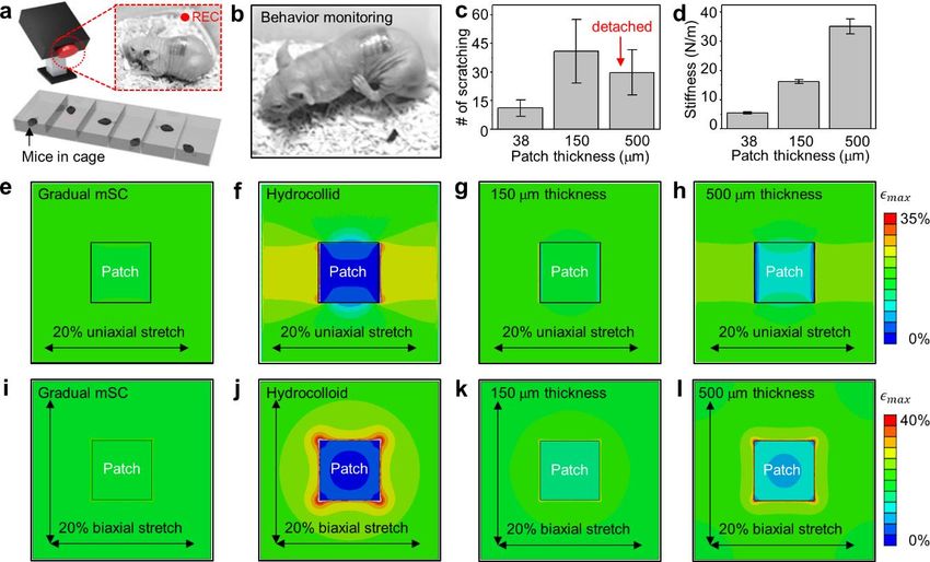
In order to quantify the degree of discomfort after wearing patches, we performed the animal behavior test by using the mouse model. For the similarity with the human skin, nude mice (Balb/c nude mice) were used. We assumed a high degree of discomfort due to the wear of patches would lead to more scratching behavior.[S2,S3] Thus the count of scraping action in three different experimental sets (mouse of bare back, back with the mSC patch, back with the commercial hydrocolloid patch) can be a good factor for the quantification of the discomfort induced by different patches. To visually observe animal behavior, we laminated patches on the back of mice and allowed the mice to swim in water for ~3 minutes. The purpose of the swimming is to remove residual PVA (water-soluble temporary supporting layer) and to confirm conformal mechanical coupling between the patch and the mouse skin. Each mouse was kept in its own cage to isolate each other. Scratching during experiments was monitored for ~3 hours across six mice. To minimize the influence of different time slots and individual differences between animals, behavior tests were carried out during the same time zone and the mice were experimented in turns. The interval of animal behavior tests spanned across ~1 week to ensure that the mice were stable. Scratching behavior in anatomical regions adjacent to the patch were included, while grooming actions were excluded. The effect of patch stiffness on comfort was also estimated via similar animal behavior tests. Ultra-soft patches of different thicknesses (~30 m, ~150 m, and ~500 m) were employed using the same experimental set-up and conditions with the aforementioned animal behavior test. The thinnest patches (~30 m) exhibited the lowest scratching number, which implies highest comfort levels, whereas the thick one resulted in the opposite (Figure S6 c and d). These trends were analyzed by comparing the number of scratches with the 4
stiffness of each patch. Stiffer (thicker) patches tended to cause more strain on the skin and

thereby more scratches/discomfort. FEM simulations (uniaxial strain for Figure S6 e-h and

biaxial strain for Figure S6 i-l) corroborated with the experimental results, i.e. the ultrasoft

mSC patch caused negligible irritation.

 5
2. Supporting Methods 2.1. Fabrication of mSC molds First, Si molds with the dot-shape trench array of ~500 nm radius and ~m height are prepared by the deep reactive ion etching (Versaline, PLASMA THERM, USA) using the inductively coupled plasma. The surface of Si molds is treated with trichloro(1H,1H,2H,2H- perfluorooctyl)silane (FOTCS) self-assembled monolayer (SAM). Then the hard polyurethane acrylate (h-PUA; MINS 311 RM, Minuta Tech., Korea) is coated and photo- cured on it. Quick detachment of the h-PUA film after its uniform filling into deep trenches of the Si mold achieves the array of mountaintop-shaped h-PUA structures on the Si mold. The weak oxygen plasma etching of the h-PUA structures on the Si mold provides a circular groove near the border of Si trench, since Si is not etched while h-PUA is etched. This groove serves as a rim of mSCs. After FOTCS SAM treatment of the prepared h-PUA/Si mold, another layer of h-PUA is coated, cured, and detached. Then, the mSC mold made of h-PUA is obtained. 2.2. Device fabrication The device fabrication begins with spin coating the precursor (~1 m thick film) of polyimide (polyamic acid, Sigma Aldrich, USA) or benzocyclobutene (cyclotene 3022, Dow Chemical, USA) on a sacrificial layer (poly(methylmethacrylate) (PMMA A2, MicroChem, USA) or thermally deposited nickel layer). 100 nm thick Boron doped Si nano-membranes are prepared from the silicon-on-insulator wafer (SOITEC, France) and then transferred onto 6
prepared polymer films. Desired geometries of electronics are achieved by photolithography and dry etching processes. A lift-off process of Ti/Pt (5/40 nm) film is used for temperature sensors. Cr/Au (7/70 nm) layers are deposited thermally and patterned by the photolithography process for serpentine-shaped interconnections. Additional spin coating forms the top polymeric passivation layer. Final patterning and dry etching steps complete the fabrication of stretchable electronic devices. 2.3. Fabrication of gecko-inspired miniaturized-pillar structure Miniaturized-pillar (m-pillar) structures, inspired by gecko setae, were fabricated through a combination of photo-/soft-lithography techniques. Photolithography and inductively-coupled-plasma-assisted deep-reactive-ion-etching patterned an array of holes (reverse structure of m-pillar) on Si wafer. Each hole pattern in this Si master has the size of 1 m diameter and 3 m depth. The negative replica mold of m-pillars was fabricated with the photo-curable poly(urethane acrylate) (PUA; MINS 301 RM, Minuta Tech., Korea). To reduce the interfacial energy, FOTCS surface modification was performed. Stretchable electronic devices were transferred onto the fully cured bottom PDMS layer (sylgard 184, Dow Corning, USA) (1.6 MPa) on poly(vinylalchol) (PVA; Kuraray, Japan) film. Another top PDMS layer (1.6 MPa) was spin-coated and partially cured at 70C oven. The negative pillar mold was laminated on the partly cured PDMS, pressed, and then completely cured in 70C oven. The final m-pillars were formed by removing the mold. 2.4. Fabrication of mSC electronic patch 7
The electronics were released from the temporary handling substrates by etching a sacrificial layer, and then transferred onto an elastomer film of ~39 kPa modulus (Ecoflex 0030, Smooth-on Inc., USA) coated on a PVA film (water-dissolvable temporary supporting layer). After super-hydrophobic treatment of the mSC mold, three PDMS prepolymer solutions diluted by toluene (concentrations: 0.5 g/mL, 1 g/mL, and 2 g/mL) were mixed with the PDMS curing agent of 0.1 g/mL concentration, respectively. The resulting PDMS mixture solutions were then spin-coated in the mSC mold in a sequential order, following spin coating of ~39 kPa PDMS. The coated film was partially cured in 70C oven and assembled with O2- plasma-treated devices on Ecoflex/PVA film. The assembled sample was strongly pressed with ~5 mm thick PDMS dampers to equally distribute the applied pressure. Full curing (in 70C oven), followed by detaching the mSC mold completed the fabrication steps. Additional electrodes for electrophysiology monitoring and iontophoresis were transfer-printed onboard the mSC structure with water soluble tapes (3M Corp., USA). 2.5. Adhesion tests and verification of conformal contacts The patch adhesive was characterized on a human skin mold (PUA duplication with human skin morphology). Patch samples with different surface structures (gradual mSC, m- pillar, 1.2 MPa mSC, 60 kPa flat) were utilized and back-supported by ~50 m thick PET films coated with 10:1 PDMS. Each sample was cut into ~1.2 cm width and the adhesion force (maximum force during dragging) was measured by a digital force gauge (Mark-10, USA). Conformal contact was verified by using the mSCs/m-pillar patches containing fluorescent dyes (rubrene, Sigma Aldrich, USA). The patches were laminated on artificial Ecoflex skin segments, and the three-dimensional interface between the patch and the skin 8
was observed via confocal microscopy (LSM780 NLO, Carl Zeiss, Germany).

2.6. Characterization of mechanical properties (system modulus)

 After dissolving the PVA film (water-dissolvable temporary supporting layer), the

patch was rolled up. Both ends of the rolled patch were fixed by the digital force meter,

which measured the induced load during stretching. The system modulus was calculated from

the slope of stress-strain curves. To characterize the modulus of the entire system stack,

similar experiments were performed across various elastomers (e.g. PDMS, Ecoflex).

2.7. Procedures for reuse of mSC patches

 The mSC patch laminated on the skin was detached by the water-soluble tape which

acted as a temporary substrate. After cleansing the patch with acetone (the ingredient of the

nail manicure remover) and reloading drugs by drop-casting the drug solution, the patch was

re-attached onto the skin. Then the water-soluble tape was easily removed from the skin with

the water. Following drying step finished the patch regeneration (Movie S3).

2.8. Monitoring human vital signs in-vivo and acute disease model

 The connector consisted of an array of metal lines was interconnected to a data-

acquisition system (National Instruments, USA) through an anisotropic conductive film.

Devices were attached on a few locations on skin, including the radial artery, joint, and chest.

After the PVA film was dissolved, the patch made conformal contacts to monitor highly

 9
sensitive physiological signals. For animal disease models, strain gauges attached on the epidermis over the heart of the mouse measured the heart rate and respiratory rate. The ethanol tap on the mouse body was utilized to induce acute hypothermia.[S4] 100 g Norepinephrine (Sigma Aldrich, USA) and 100 g propranolol (Sigma Aldrich, USA) diluted with phosphate buffered solution were intravascular injected to cause and alleviate acute hypertensive emergency.[S5] Injection of desire-sized thrombus which was formed from mouse blood into inferior vena cava led to blocking pulmonary capillary (pulmonary thromboembolism). [S6] 2.9. Wireless communication system The custom-made wireless communication system equipped on the smart band was built. It consists of a controller, Bluetooth unit (Arduino Pro Mini, Sparkfun, USA), and battery (Figure S3a). The medical devices on mSC patches were connected to the external commercial devices (e.g. tablets or smartphones) wirelessly through Bluetooth module of the smart band. Data was transferred to external devices from mSC patches and commands were delivered vice versa. For instance, the resistance change of strain gauges was measured through the specially designed resistor-capacitor (RC) circuit (Figure S3b). The resistance alternation modulated the discharging time of capacitor, which was detected by the controller unit and wirelessly transferred to external devices through Bluetooth unit. A Labview (National Instruments, USA) program analyzed the RC delay and changed over to original resistance values. The program also monitored the motion of high-risk patients, such as tremors, and sent alarms in emergency situations (Movie S1). Another program installed in controller unit can remotely turn on/off the iontophoresis actuator by using smartphone 10
applications (SPLDuino Lite, Helloapps, USA) (Movie S2). 2.10. Synthesis of RITC-doped mesoporous silica nanoparticles with enlarged nanopores 44 L of 3-aminopropyltriethoxysilane (APTES; Aldrich, USA), 10 mg of rhodamine B isothiocyanate (RITC; Aldrich, USA), and 1 mL of anhydrous ethanol (Aldrich, USA) were mixed and stirred overnight under the dark condition. Amine group in APTES and isothiocyanate group in RITC were covalently conjugated. The solution was stored in the refrigerator and used without further purifications. To synthesize RITC-doped mesoporous silica nanoparticles with enlarged nanopores (RITC-MSN-L), previous method[S7] was adopted and modified. In details, 3 g of hexadecyl trimethyl ammonium chloride solution (CTAC, 25 wt% in water; Aldrich, USA), 90 mg of triethanolamine (Samchun, Korea), and 30 mL of deionized water were mixed. The solution was heated to 95C with vigorous stirring. After 1 hour, 2.5 mL of trimethylbenzene (TMB; Aldrich, USA) was added and 2.25 mL of tetraethylorthosilicate (TEOS; Acros, USA) and 225 L of RITC-APTES solution were injected simultaneously. The resulting solution was aged for another 1 hour. The products were centrifuged and washed for several times with deionized water and ethanol to remove unreacted precursors, and dispersed in ethanol. To remove the template (hexadecyl trimethyl ammonium cation in mesopores), 500 L of HCl (35%; Samchun, Korea) was added and stirred at 60C for 1 hour. Then, products were centrifuged and washed by anhydrous ethanol for several times and redispersed in anhydrous ethanol (25 mL). To functionalize RITC- MSN-L with amine groups, 100 L of APTES was added to ethanol solution containing RITC-MSN-L. To accelerate the reaction, the mixture was refluxed for 3 hours. After the centrifugation and washing with anhydrous ethanol, amine-functionalized RITC-MSN-L was 11
redispersed in 10 mL of anhydrous ethanol. PEG was covalently conjugated onto RITC- MSN-L-NH2. 100 mg of mPEG-SG 5000 (Succinimidyl glutarate terminated; Sunbio, Korea) was added to RITC-MSN-L-NH2 solution and stirred overnight at 35C. After reaction was completed, products were centrifuged and washed with ethanol and redispersed in 10 mL of chloroform. 2.11. Immunofluorescence and western blot analysis The skin tissues were embedded in optimal cutting temperature (OCT) compound and were sliced at coronal plane to 10 m thick by microtome (Leica, Germany). This sliced tissues were mounted on slides, and stained with Hematoxylin-Eosin (MHS16, HT110180, Sigma aldrich, USA) by standard histochemical procedure. For the Figure S7c, the H&E staining of mouse skin was immediately performed after detaching the laminated patches. Moreover, to prepare immunofluorescence imaging of inflammation factors, we utilized IL-1 (SC-7884, Santa Cruz Biotechnology, USA) and iNOS (2982S, Cell Signaling Technology, USA) by standard protocol. For the western blot, lysates of skin tissue were prepared with Lysis buffer, which were made of 150 mM NaCl, 50 mM Tris-HCl (pH 7.4), 1% NP-40, 0.1% Sodium Dodecyl Sulfate (SDS), 1 mM Sodium orthovanadate (Na3VO4), 5 mM Sodium Fluoride (NaF), 0.25% Sodium Deoxycholate, 5 mM N-Ethylmethylamine, and protease inhibitor cocktail (Roche, Switzerland). The protein concentration was determined with BCA Protein Assay kit (Thermo Fisher Scientific, USA). Tissue lysate samples were separated on 4-12% Bis-Tris Plus gel (Thermo Fisher Scientific, USA) with MES buffer (50 mM MES, 50 mM Tris Base, 0.1% SDS, 1 mM EDTA, pH 7.3) and transferred to Polyvinylidene difluoride (PVDF) membrane with 0.2 micrometer pores (Bio-rad., USA). 12
The blots were incubated with primary antibodies: mouse anti-TNF (1:500, Abcam, USA), mouse anti-IL-1 (1:500, Cell Signaling Technology, USA), and mouse-anti -actin (1:20000, Sigma, USA). After that, all blots were incubated with secondary antibody: goat anti-mouse IgG-HRP (Santa Cruz Biotechnology, USA). The blot images were captured using the Fusion FX7 system (Vilber Lourmat, Germany) and band density was analyzed by Bio-1D program (Vilber Lourmat, Germany). 2.12. Laboratory animals Balb/c nude mice (age: 6 weeks) were obtained from the Experimental Animal Center, Chuncheon Center, Korea Basic Science Institute (KBSI), Chuncheon, South Korea. These animals were individually housed in transparent plastic cages with wire grid covers under controlled temperatures (22-24C) with the 12 hour light/dark cycle (lights on from 08:00 to 20:00). All animal procedures were in accordance with the Guide for the Care and Use of Laboratory Animals issued by the Laboratory Animal Resources Commission of KBSI. The Institutional Animal Care and Use Committee at the KBSI (KBSI-AEC1409) reviewed and approved this study. All of the experiments were conducted to minimize the number of animals used and the suffering caused by the procedures used in the current study. 13
3. Supporting References

[S1] J. D. Eshelby, Proc. R. Soc. A 1957, 241, 376.

[S2] R. H. LaMotte, S. G. Shimada, P. Sikand, Exp. Dermatol. 2011, 20, 778.

[S3] S. G. Shimada, R. H. LaMotte, Pain 2008, 139, 681.

[S4] W. C. M. Cramer, G. P. Toorop, Gen. Pharmacol. 1998, 30, 195.

[S5] J. Polio, C. C. Sieber, E. Lerner, R. J. Groszmann, Hepatology 1993, 18, 128.

[S6] M. H. Todd, J. B. Forrest, D. B. J. Cragg, Am. Heart J. 1983, 105, 769.

[S7] L. Pan, Q. He, J. Liu, Y. Chen, M. Ma, L. Zhang, J. Shi, J. Am. Chem. Soc. 2012,
 134, 5722.

 14
4. Supporting Figures

Figure S1. Exploded view of mSC electronic patch. The strain gauge and temperature sensor

array (image in the middle) is embedded between silicone rubber (Ecoflex; cartoon at the

bottom) and top mSCs structured elastomer layer (PDMS; cartoon at the top). The electrodes

(topmost image) are located on the surface of the electronic patch.

 15
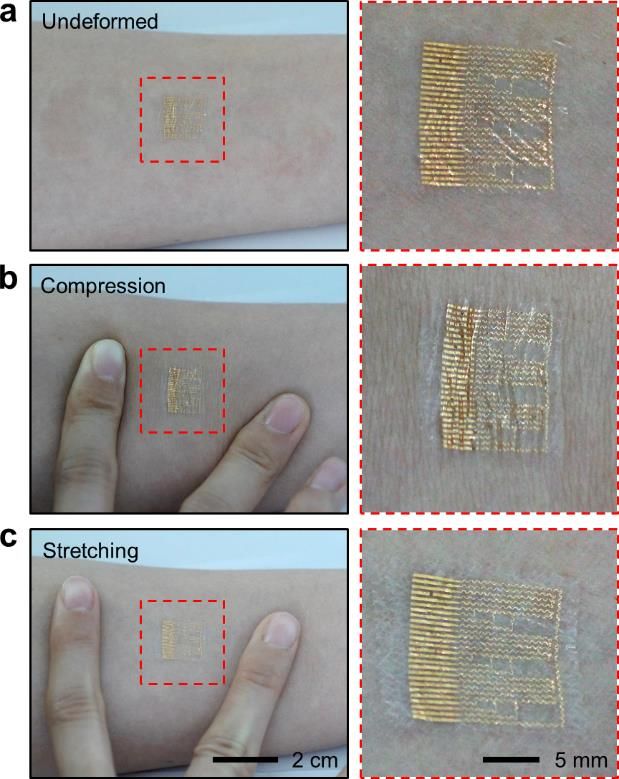
Figure S2. a-c, The mSCs electronic patch laminated on skin: undeformed (a), compressed

(b), and stretched (c) states. Photographs (right column) show magnified view of each state in

the red dotted box.

Figure S3. a, Image of a custom-made smart band that consists of a Bluetooth unit, a battery,

and a controller unit. b, Schematic diagram of the smart band circuit for the real time sensing,

wireless data transfer to external devices, and remote control of the electronics in the patch

using commercial devices such as a smartphone.

 16
You can also read