OPERATING MANUAL LINEAR AXIS BETRIEBSANWEISUNG LINEARACHSEN - NTN SNR
←
→
Page content transcription
If your browser does not render page correctly, please read the page content below
OPERATING MANUAL LINEAR AXIS BETRIEBSANWEISUNG LINEARACHSEN
Manufacturer / Hersteller
    SNR WÄLZLAGER GMBH
    Friedrich-Hagemann-Straße 66
    D-33719 Bielefeld
    Tel.: +49 (0) 521 924 00 112

    email: linear.motion@ntn-snr.com

    www.ntn-snr.com/documents/linear

NTN-SNR does not acknowledge any liability for any errors and omissions deficiencies occurring - despite our great care – with reference
to the publication of this technical document. We are entitled to make any complete or partial changes to products or characteristics/data
in/of this document in accordance to our continuous research and development policy, without prior notice.

NTN-SNR übernimmt keine Haftung - für trotz aller Sorgfalt - bei der Erstellung des technischen Dokuments auftretende Fehler oder
Auslassungen. Wir behalten uns vollständige oder teilweise Änderungen an Produkten und Daten im vorliegenden Dokument im Rahmen
unserer kontinuierlichen Forschungs- und Entwicklungsarbeit ohne vorherige Mitteilung vor.

NTN-SNR Copyright International 2018.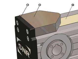
Table of contents
     1.____System technology. .  .  .  .  .  .  .  .  .  .  .  .  .  .  .  .  .  .  .  .  .  .  .  .  .  .  .  .  .  .  .  .  .  .  .  .  .  .  .  .  .  .  .  .  .  .  .  .  .  .  .  .                                             GB 5
     1.1____         Definition.  .  .  .  .  .  .  .  .  .  .  .  .  .  .  .  .  .  .  .  .  .  .  .  .  .  .  .  .  .  .  .  .  .  .  .  .  .  .  .  .  .  .  .  .  .  .  .  .  .  .  .  .  .  .  .  .  .  .  .  .  .  .  .  .  . GB 5
     1.2____        Declaration of incorporation for partly completed machinery (Machinery directive 2006/42/EG).  .  .  . GB 5
     1.3____        Safety instructions .  .  .  .  .  .  .  .  .  .  .  .  .  .  .  .  .  .  .  .  .  .  .  .  .  .  .  .  .  .  .  .  .  .  .  .  .  .  .  .  .  .  .  .  .  .  .  .  .  .  .  .  .  .  .  .  .  .  . GB 6
     1.4____        Intended use .  .  .  .  .  .  .  .  .  .  .  .  .  .  .  .  .  .  .  .  .  .  .  .  .  .  .  .  .  .  .  .  .  .  .  .  .  .  .  .  .  .  .  .  .  .  .  .  .  .  .  .  .  .  .  .  .  .  .  .  .  .  . GB 6
     1.5____        Coordinate system .  .  .  .  .  .  .  .  .  .  .  .  .  .  .  .  .  .  .  .  .  .  .  .  .  .  .  .  .  .  .  .  .  .  .  .  .  .  .  .  .  .  .  .  .  .  .  .  .  .  .  .  .  .  .  .  .  .  . GB 6
     1.6____        Static load capacity .  .  .  .  .  .  .  .  .  .  .  .  .  .  .  .  .  .  .  .  .  .  .  .  .  .  .  .  .  .  .  .  .  .  .  .  .  .  .  .  .  .  .  .  .  .  .  .  .  .  .  .  .  .  .  .  .  . GB 7
     1.7____        Life time .  .  .  .  .  .  .  .  .  .  .  .  .  .  .  .  .  .  .  .  .  .  .  .  .  .  .  .  .  .  .  .  .  .  .  .  .  .  .  .  .  .  .  .  .  .  .  .  .  .  .  .  .  .  .  .  .  .  .  .  .  .  .  .  .  . GB 7
     1.7.1___       Dynamic load capacity / Nominal life time .  .  .  .  .  .  .  .  .  .  .  .  .  .  .  .  .  .  .  .  .  .  .  .  .  .  .  .  .  .  .  .  .  .  .  .  .  .  .  .  .  . GB 7
     1.7.2___       Influence factors. .  .  .  .  .  .  .  .  .  .  .  .  .  .  .  .  .  .  .  .  .  .  .  .  .  .  .  .  .  .  .  .  .  .  .  .  .  .  .  .  .  .  .  .  .  .  .  .  .  .  .  .  .  .  .  .  .  .  .  . GB 7
     1.8____        Rigidity .  .  .  .  .  .  .  .  .  .  .  .  .  .  .  .  .  .  .  .  .  .  .  .  .  .  .  .  .  .  .  .  .  .  .  .  .  .  .  .  .  .  .  .  .  .  .  .  .  .  .  .  .  .  .  .  .  .  .  .  .  .  .  .  .  .  . GB 8
     1.9____        Dynamic operating load .  .  .  .  .  .  .  .  .  .  .  .  .  .  .  .  .  .  .  .  .  .  .  .  .  .  .  .  .  .  .  .  .  .  .  .  .  .  .  .  .  .  .  .  .  .  .  .  .  .  .  .  .  .  . GB 9
     1.10___        Precision.  .  .  .  .  .  .  .  .  .  .  .  .  .  .  .  .  .  .  .  .  .  .  .  .  .  .  .  .  .  .  .  .  .  .  .  .  .  .  .  .  .  .  .  .  .  .  .  .  .  .  .  .  .  .  .  .  .  .  .  .  .  .  .  .  . GB 9
     1.11___        Gearbox selection. .  .  .  .  .  .  .  .  .  .  .  .  .  .  .  .  .  .  .  .  .  .  .  .  .  .  .  .  .  .  .  .  .  .  .  .  .  .  .  .  .  .  .  .  .  .  .  .  .  .  .  .  .  .  .  .  .  . GB 10
     1.11.1__       Maximum operation speed .  .  .  .  .  .  .  .  .  .  .  .  .  .  .  .  .  .  .  .  .  .  .  .  .  .  .  .  .  .  .  .  .  .  .  .  .  .  .  .  .  .  .  .  .  .  .  .  .  .  .  . GB 10
     1.11.2__       Maximum acceleration torque.  .  .  .  .  .  .  .  .  .  .  .  .  .  .  .  .  .  .  .  .  .  .  .  .  .  .  .  .  .  .  .  .  .  .  .  .  .  .  .  .  .  .  .  .  .  .  .  .  . GB 10
     1.11.3__        Nominal torque on the drive .  .  .  .  .  .  .  .  .  .  .  .  .  .  .  .  .  .  .  .  .  .  .  .  .  .  .  .  .  .  .  .  .  .  .  .  .  .  .  .  .  .  .  .  .  .  .  .  .  .  . GB 10
     1.12___         Drive calculation. .  .  .  .  .  .  .  .  .  .  .  .  .  .  .  .  .  .  .  .  .  .  .  .  .  .  .  .  .  .  .  .  .  .  .  .  .  .  .  .  .  .  .  .  .  .  .  .  .  .  .  .  .  .  .  .  .  .  . GB 11
     1.13___         Selection of Linear Axis with toothed belt drive for 90 ° tilt mounting (wall mounting).  .  .  .  .  .  .  .  .  .  . GB 11

     2.____Mounting and Start-up.  .  .  .  .  .  .  .  .  .  .  .  .  .  .  .  .  .  .  .  .  .  .  .  .  .  .  .  .  .  .  .  .  .  .  .  .  .  .  .  .  .  .  .  .  .  .  .                                              GB 12
     2.1____        Transportation and storage .  .  .  .  .  .  .  .  .  .  .  .  .  .  .  .  .  .  .  .  .  .  .  .  .  .  .  .  .  .  .  .  .  .  .  .  .  .  .  .  .  .  .  .  .  .  .  .  .  .  .  .                   GB 12
     2.2____        Design of the mounting surfaces / mounting tolerances .  .  .  .  .  .  .  .  .  .  .  .  .  .  .  .  .  .  .  .  .  .  .  .  .  .  .  .  .  .  .                                                       GB 12
     2.3____        Mounting instruction. .  .  .  .  .  .  .  .  .  .  .  .  .  .  .  .  .  .  .  .  .  .  .  .  .  .  .  .  .  .  .  .  .  .  .  .  .  .  .  .  .  .  .  .  .  .  .  .  .  .  .  .  .  .  .  .            GB 14
     2.4____        Mounting of parallel Linear Axis.  .  .  .  .  .  .  .  .  .  .  .  .  .  .  .  .  .  .  .  .  .  .  .  .  .  .  .  .  .  .  .  .  .  .  .  .  .  .  .  .  .  .  .  .  .  .  .  .                       GB 15
     2.5____        Start-up of Linear Axis .  .  .  .  .  .  .  .  .  .  .  .  .  .  .  .  .  .  .  .  .  .  .  .  .  .  .  .  .  .  .  .  .  .  .  .  .  .  .  .  .  .  .  .  .  .  .  .  .  .  .  .  .  .  .             GB 16
     2.6____        Assembly of couplings on Linear Axis with toothed belt drive.  .  .  .  .  .  .  .  .  .  .  .  .  .  .  .  .  .  .  .  .  .  .  .  .  .  .  .                                                         GB 16
     2.7____         Drive assembly. .  .  .  .  .  .  .  .  .  .  .  .  .  .  .  .  .  .  .  .  .  .  .  .  .  .  .  .  .  .  .  .  .  .  .  .  .  .  .  .  .  .  .  .  .  .  .  .  .  .  .  .  .  .  .  .  .  .  .  .     GB 17
     2.7.1___        Drive assembly on Linear Axis with toothed belt drive and coupling cone .  .  .  .  .  .  .  .  .  .  .  .  .  .  .  .  .  .  .                                                                       GB 17
     2.7.2___         Drive assembly on Linear Axis with toothed belt drive and planetary gearbox .  .  .  .  .  .  .  .  .  .  .  .  .  .  .  .                                                                           GB 17
     2.7.3___          Drive assembly on Linear Axis and Linear Tables with screw drive .  .  .  .  .  .  .  .  .  .  .  .  .  .  .  .  .  .  .  .  .  .  .  .                                                             GB 19
     2.8____            Assembly of a deflection belt drive on Linear Axis and Linear Tables with screw drive .  .  .  .  .  .  .  .  .  .                                                                                 GB 20

     3.____Maintenance and lubrication. .  .  .  .  .  .  .  .  .  .  .  .  .  .  .  .  .  .  .  .  .  .  .  .  .  .  .  .  .  .  .  .  .  .  .  .  .  .  .  .  .                                                            GB 22
     3.1____        General information .  .  .  .  .  .  .  .  .  .  .  .  .  .  .  .  .  .  .  .  .  .  .  .  .  .  .  .  .  .  .  .  .  .  .  .  .  .  .  .  .  .  .  .  .  .  .  .  .  .  .  .  .  .  .  .  . GB 22
     3.2____        Lubrication. .  .  .  .  .  .  .  .  .  .  .  .  .  .  .  .  .  .  .  .  .  .  .  .  .  .  .  .  .  .  .  .  .  .  .  .  .  .  .  .  .  .  .  .  .  .  .  .  .  .  .  .  .  .  .  .  .  .  .  .  .  .  . GB 22
     3.3____        Lubricants.  .  .  .  .  .  .  .  .  .  .  .  .  .  .  .  .  .  .  .  .  .  .  .  .  .  .  .  .  .  .  .  .  .  .  .  .  .  .  .  .  .  .  .  .  .  .  .  .  .  .  .  .  .  .  .  .  .  .  .  .  .  .  . GB 22
     3.4____        Lubrication methods.  .  .  .  .  .  .  .  .  .  .  .  .  .  .  .  .  .  .  .  .  .  .  .  .  .  .  .  .  .  .  .  .  .  .  .  .  .  .  .  .  .  .  .  .  .  .  .  .  .  .  .  .  .  .  .  . GB 24
     3.4.1___       Manual grease guns.  .  .  .  .  .  .  .  .  .  .  .  .  .  .  .  .  .  .  .  .  .  .  .  .  .  .  .  .  .  .  .  .  .  .  .  .  .  .  .  .  .  .  .  .  .  .  .  .  .  .  .  .  .  .  .  . GB 24
     3.4.2___       Automatic electro-mechanical lubricator DRIVE BOOSTER.  .  .  .  .  .  .  .  .  .  .  .  .  .  .  .  .  .  .  .  .  .  .  .  .  .  .  .  .  . GB 25
     3.4.3___        Central lubrication system CONTROL BOOSTER .  .  .  .  .  .  .  .  .  .  .  .  .  .  .  .  .  .  .  .  .  .  .  .  .  .  .  .  .  .  .  .  .  .  .  . GB 25
     3.5____         Lubrication points. .  .  .  .  .  .  .  .  .  .  .  .  .  .  .  .  .  .  .  .  .  .  .  .  .  .  .  .  .  .  .  .  .  .  .  .  .  .  .  .  .  .  .  .  .  .  .  .  .  .  .  .  .  .  .  .  .  . GB 26
     3.6____         Amounts of lubricant. . . . . . . . . . . . . . . . . . . . . . . . . . . . . . . . . . . . . . . . . . . . . . . . . . . . . . . . .GB 28
     3.7____         Lubrication intervals.  .  .  .  .  .  .  .  .  .  .  .  .  .  .  .  .  .  .  .  .  .  .  .  .  .  .  .  .  .  .  .  .  .  .  .  .  .  .  .  .  .  .  .  .  .  .  .  .  .  .  .  .  .  .  .  . GB 31
     3.8 ____        Brush wiper replacement .  .  .  .  .  .  .  .  .  .  .  .  .  .  .  .  .  .  .  .  .  .  .  .  .  .  .  .  .  .  .  .  .  .  .  .  .  .  .  .  .  .  .  .  .  .  .  .  .  .  .  .  . GB 33
     3.9____         Cover strip replacement .  .  .  .  .  .  .  .  .  .  .  .  .  .  .  .  .  .  .  .  .  .  .  .  .  .  .  .  .  .  .  .  .  .  .  .  .  .  .  .  .  .  .  .  .  .  .  .  .  .  .  .  .  . GB 33
     3.9.1___        Cover strip repalcement for Linear Axis of the series AXC .  .  .  .  .  .  .  .  .  .  .  .  .  .  .  .  .  .  .  .  .  .  .  .  .  .  .  .  .  . GB 33
     3.9.2___        Cover strip repalcement for Linear Axis of the series AXDL .  .  .  .  .  .  .  .  .  .  .  .  .  .  .  .  .  .  .  .  .  .  .  .  .  .  .  .  . GB 35
     3.10___          Wear part sets.  .  .  .  .  .  .  .  .  .  .  .  .  .  .  .  .  .  .  .  .  .  .  .  .  .  .  .  .  .  .  .  .  .  .  .  .  .  .  .  .  .  .  .  .  .  .  .  .  .  .  .  .  .  .  .  .  .  .  .  . GB 35

                                                                                                               GB 3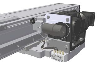
Inhalt
         1.____Systemtechnologie .  .  .  .  .  .  .  .  .  .  .  .  .  .  .  .  .  .  .  .  .  .  .  .  .  .  .  .  .  .  .  .  .  .  .  .  .  .  .  .  .  .  .  .  .  .  .  .  .  .  .  .  .  .  .                                             D5
         1.1____         Definitionen.  .  .  .  .  .  .  .  .  .  .  .  .  .  .  .  .  .  .  .  .  .  .  .  .  .  .  .  .  .  .  .  .  .  .  .  .  .  .  .  .  .  .  .  .  .  .  .  .  .  .  .  .  .  .  .  .  .  .  .  .  .  .  .  .  .  . D 5
         1.2____         Einbauerklärung für eine unvollständige Maschine (Machinery directive 2006/42/EG) .  .  .  .  .  .  .  .  .  .  .  .  . D 5
         1.3____         Sicherheitshinweise.  .  .  .  .  .  .  .  .  .  .  .  .  .  .  .  .  .  .  .  .  .  .  .  .  .  .  .  .  .  .  .  .  .  .  .  .  .  .  .  .  .  .  .  .  .  .  .  .  .  .  .  .  .  .  .  .  .  .  .  . D 6
         1.4____          Bestimmungsgemäße Verwendung.  .  .  .  .  .  .  .  .  .  .  .  .  .  .  .  .  .  .  .  .  .  .  .  .  .  .  .  .  .  .  .  .  .  .  .  .  .  .  .  .  .  .  .  .  .  .  .  .  . D 6
         1.5____          Koordinatensystem .  .  .  .  .  .  .  .  .  .  .  .  .  .  .  .  .  .  .  .  .  .  .  .  .  .  .  .  .  .  .  .  .  .  .  .  .  .  .  .  .  .  .  .  .  .  .  .  .  .  .  .  .  .  .  .  .  .  .  .  . D 6
         1.6____          Statische Belastbarkeit. .  .  .  .  .  .  .  .  .  .  .  .  .  .  .  .  .  .  .  .  .  .  .  .  .  .  .  .  .  .  .  .  .  .  .  .  .  .  .  .  .  .  .  .  .  .  .  .  .  .  .  .  .  .  .  .  .  . D 7
         1.7____          Lebensdauer.  .  .  .  .  .  .  .  .  .  .  .  .  .  .  .  .  .  .  .  .  .  .  .  .  .  .  .  .  .  .  .  .  .  .  .  .  .  .  .  .  .  .  .  .  .  .  .  .  .  .  .  .  .  .  .  .  .  .  .  .  .  .  .  .  . D 7
         1.7.1.__         Dynamische Belastbarkeit / nominelle Lebensdauer.  .  .  .  .  .  .  .  .  .  .  .  .  .  .  .  .  .  .  .  .  .  .  .  .  .  .  .  .  .  .  .  .  .  .  .  .  . D 7
         1.7.2.__         Einflussfaktoren.  .  .  .  .  .  .  .  .  .  .  .  .  .  .  .  .  .  .  .  .  .  .  .  .  .  .  .  .  .  .  .  .  .  .  .  .  .  .  .  .  .  .  .  .  .  .  .  .  .  .  .  .  .  .  .  .  .  .  .  .  .  .  . D 7
         1.8____          Steifigkeit .  .  .  .  .  .  .  .  .  .  .  .  .  .  .  .  .  .  .  .  .  .  .  .  .  .  .  .  .  .  .  .  .  .  .  .  .  .  .  .  .  .  .  .  .  .  .  .  .  .  .  .  .  .  .  .  .  .  .  .  .  .  .  .  .  .  .  . D 8
         1.9____          Dynamische Betriebslast .  .  .  .  .  .  .  .  .  .  .  .  .  .  .  .  .  .  .  .  .  .  .  .  .  .  .  .  .  .  .  .  .  .  .  .  .  .  .  .  .  .  .  .  .  .  .  .  .  .  .  .  .  .  .  .  . D 9
         1.10___          Präzision.  .  .  .  .  .  .  .  .  .  .  .  .  .  .  .  .  .  .  .  .  .  .  .  .  .  .  .  .  .  .  .  .  .  .  .  .  .  .  .  .  .  .  .  .  .  .  .  .  .  .  .  .  .  .  .  .  .  .  .  .  .  .  .  .  .  .  .  . D 9
         1.11___          Getriebeauswahl .  .  .  .  .  .  .  .  .  .  .  .  .  .  .  .  .  .  .  .  .  .  .  .  .  .  .  .  .  .  .  .  .  .  .  .  .  .  .  .  .  .  .  .  .  .  .  .  .  .  .  .  .  .  .  .  .  .  .  .  .  . D 10
         1.11.1._         Maximale Betriebsdrehzahl. .  .  .  .  .  .  .  .  .  .  .  .  .  .  .  .  .  .  .  .  .  .  .  .  .  .  .  .  .  .  .  .  .  .  .  .  .  .  .  .  .  .  .  .  .  .  .  .  .  .  .  .  .  . D 10
         1.11.2._         Maximales Beschleunigungsmoment. . . . . . . . . . . . . . . . . . . . . . . . . . . . . . . . . . . . . . . . . . . . . . . .D 10
         1.11.3._          Nenndrehmoment am Antrieb.  .  .  .  .  .  .  .  .  .  .  .  .  .  .  .  .  .  .  .  .  .  .  .  .  .  .  .  .  .  .  .  .  .  .  .  .  .  .  .  .  .  .  .  .  .  .  .  .  .  .  .  . D 10
         1.12___           Antriebsauslegung.  .  .  .  .  .  .  .  .  .  .  .  .  .  .  .  .  .  .  .  .  .  .  .  .  .  .  .  .  .  .  .  .  .  .  .  .  .  .  .  .  .  .  .  .  .  .  .  .  .  .  .  .  .  .  .  .  .  .  .  . D 11
         1.13___          Auswahl von Linearachsen mit Zahnriemenantrieb für um 90° gekippte Montage (Wandmontage).  .  . D 11

         2.____Montage und Inbetriebnahme.  .  .  .  .  .  .  .  .  .  .  .  .  .  .  .  .  .  .  .  .  .  .  .  .  .  .  .  .  .  .  .  .  .  .  .  .  .  .  .  .  .  .                                                                    D 12
         2.1____              Transport und Lagerung.  .  .  .  .  .  .  .  .  .  .  .  .  .  .  .  .  .  .  .  .  .  .  .  .  .  .  .  .  .  .  .  .  .  .  .  .  .  .  .  .  .  .  .  .  .  .  .  .  .  .  .  .  .  .  .  .               D 12
         2.2____              Gestaltung Montageflächen / Montagetoleranzen. .  .  .  .  .  .  .  .  .  .  .  .  .  .  .  .  .  .  .  .  .  .  .  .  .  .  .  .  .  .  .  .  .  .  .  .  .  .                                               D 12
         2.3____              Montageanleitung .  .  .  .  .  .  .  .  .  .  .  .  .  .  .  .  .  .  .  .  .  .  .  .  .  .  .  .  .  .  .  .  .  .  .  .  .  .  .  .  .  .  .  .  .  .  .  .  .  .  .  .  .  .  .  .  .  .  .  .  .        D 12
         2.4____              Montage von parallelen Linearachsen.  .  .  .  .  .  .  .  .  .  .  .  .  .  .  .  .  .  .  .  .  .  .  .  .  .  .  .  .  .  .  .  .  .  .  .  .  .  .  .  .  .  .  .  .  .  .                                D 12
         2.5____              Inbetriebnahme von Linearachsen. .  .  .  .  .  .  .  .  .  .  .  .  .  .  .  .  .  .  .  .  .  .  .  .  .  .  .  .  .  .  .  .  .  .  .  .  .  .  .  .  .  .  .  .  .  .  .  .  .                            D 16
         2.6____             Montage von Kupplungen an Linearachsen mit Zahnriementrieb. .  .  .  .  .  .  .  .  .  .  .  .  .  .  .  .  .  .  .  .  .  .  .  .  .  .  .                                                                   D 16
         2.7____             Motormontage.  .  .  .  .  .  .  .  .  .  .  .  .  .  .  .  .  .  .  .  .  .  .  .  .  .  .  .  .  .  .  .  .  .  .  .  .  .  .  .  .  .  .  .  .  .  .  .  .  .  .  .  .  .  .  .  .  .  .  .  .  .  .  .     D 17
         2.7.1.__           Motormontage an Linearachsen mit Zahnriemenantrieb und Kupplungsglocke. .  .  .  .  .  .  .  .  .  .  .  .  .  .  .  .  .                                                                                      D 17
         2.7.2.__          Motormontage an Linearachsen mit Zahnriemenantrieb und Planetengetriebe.  .  .  .  .  .  .  .  .  .  .  .  .  .  .  .  .  .                                                                                     D 17
         2.7.3.__         Motormontage an Linearachsen und Lineartischen mit Spindelantrieb. .  .  .  .  .  .  .  .  .  .  .  .  .  .  .  .  .  .  .  .  .  .  .                                                                           D 19
         2.8____         Montage eines Umlenkriementriebs an Linearachsen und Lineartischen mit Spindelantrieb .  .  .  .  .  .  .  .                                                                                                      D 20

         3.____Wartung und Schmierung .  .  .  .  .  .  .  .  .  .  .  .  .  .  .  .  .  .  .  .  .  .  .  .  .  .  .  .  .  .  .  .  .  .  .  .  .  .  .  .  .  .  .  .  .  .  .                                                           D 22
         3.1____          Allgemeine Informationen. .  .  .  .  .  .  .  .  .  .  .  .  .  .  .  .  .  .  .  .  .  .  .  .  .  .  .  .  .  .  .  .  .  .  .  .  .  .  .  .  .  .  .  .  .  .  .  .  .  .  .  .  .  .  .                     D 22
         3.2____          Schmierung. .  .  .  .  .  .  .  .  .  .  .  .  .  .  .  .  .  .  .  .  .  .  .  .  .  .  .  .  .  .  .  .  .  .  .  .  .  .  .  .  .  .  .  .  .  .  .  .  .  .  .  .  .  .  .  .  .  .  .  .  .  .  .  .  .     D 22
         3.3____          Schmierstoffe .  .  .  .  .  .  .  .  .  .  .  .  .  .  .  .  .  .  .  .  .  .  .  .  .  .  .  .  .  .  .  .  .  .  .  .  .  .  .  .  .  .  .  .  .  .  .  .  .  .  .  .  .  .  .  .  .  .  .  .  .  .  .  .      D 22
         3.4____          Schmiermethoden.  .  .  .  .  .  .  .  .  .  .  .  .  .  .  .  .  .  .  .  .  .  .  .  .  .  .  .  .  .  .  .  .  .  .  .  .  .  .  .  .  .  .  .  .  .  .  .  .  .  .  .  .  .  .  .  .  .  .  .  .              D 24
         3.4.1.__         Fettpressen.  .  .  .  .  .  .  .  .  .  .  .  .  .  .  .  .  .  .  .  .  .  .  .  .  .  .  .  .  .  .  .  .  .  .  .  .  .  .  .  .  .  .  .  .  .  .  .  .  .  .  .  .  .  .  .  .  .  .  .  .  .  .  .  .  .   D 24
         3.4.2.__        Automatische elektromechanische Schmiervorrichtung DRIVE BOOSTER. .  .  .  .  .  .  .  .  .  .  .  .  .  .  .  .  .  .  .  .  .                                                                                   D 25
         3.4.3.__        Zentralschmierungen.  .  .  .  .  .  .  .  .  .  .  .  .  .  .  .  .  .  .  .  .  .  .  .  .  .  .  .  .  .  .  .  .  .  .  .  .  .  .  .  .  .  .  .  .  .  .  .  .  .  .  .  .  .  .  .  .  .  .                 D 25
         3.5____         Schmierstellen. .  .  .  .  .  .  .  .  .  .  .  .  .  .  .  .  .  .  .  .  .  .  .  .  .  .  .  .  .  .  .  .  .  .  .  .  .  .  .  .  .  .  .  .  .  .  .  .  .  .  .  .  .  .  .  .  .  .  .  .  .  .  .        D 26
         3.6____         Schmiermengen .  .  .  .  .  .  .  .  .  .  .  .  .  .  .  .  .  .  .  .  .  .  .  .  .  .  .  .  .  .  .  .  .  .  .  .  .  .  .  .  .  .  .  .  .  .  .  .  .  .  .  .  .  .  .  .  .  .  .  .  .  .             D 28
         3.7____         Schmierintervalle.  .  .  .  .  .  .  .  .  .  .  .  .  .  .  .  .  .  .  .  .  .  .  .  .  .  .  .  .  .  .  .  .  .  .  .  .  .  .  .  .  .  .  .  .  .  .  .  .  .  .  .  .  .  .  .  .  .  .  .  .  .          D 31
         3.8____         Austausch Bürstenabstreifer. .  .  .  .  .  .  .  .  .  .  .  .  .  .  .  .  .  .  .  .  .  .  .  .  .  .  .  .  .  .  .  .  .  .  .  .  .  .  .  .  .  .  .  .  .  .  .  .  .  .  .  .  .                         D 33
         3.9____         Austausch Abdeckband .  .  .  .  .  .  .  .  .  .  .  .  .  .  .  .  .  .  .  .  .  .  .  .  .  .  .  .  .  .  .  .  .  .  .  .  .  .  .  .  .  .  .  .  .  .  .  .  .  .  .  .  .  .  .  .  .                     D 33
         3.9.1.__        Austausch Abdeckband bei Linearachsen der Baureihe AXC.  .  .  .  .  .  .  .  .  .  .  .  .  .  .  .  .  .  .  .  .  .  .  .  .  .  .  .  .  .  .                                                                  D 33
         3.9.2.__        Austausch Abdeckband bei Linearachsen der Baureihe AXDL.  .  .  .  .  .  .  .  .  .  .  .  .  .  .  .  .  .  .  .  .  .  .  .  .  .  .  .  .  .                                                                    D 35
         3.10___         Verschleißteil - Sets.  .  .  .  .  .  .  .  .  .  .  .  .  .  .  .  .  .  .  .  .  .  .  .  .  .  .  .  .  .  .  .  .  .  .  .  .  .  .  .  .  .  .  .  .  .  .  .  .  .  .  .  .  .  .  .  .  .  .  .            D 35

                                                                                                                 D 4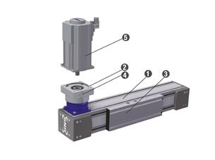
1.         System technology
1.1        Definition
Linear Axis are pre-finished units with a combination of precise guiding and driving elements. Thereby Linear Axis with their variations
are cost efficient and extremely compact components for machines and systems which could be mounted and placed into operation
within a short time.

The selection of Linear Axis could be based on following criteria:

POSITIONING                 When positioning repeatability, an arbitrary point is approached several times in one direction from the
REPEATABILITY               same starting point and the deviation to the target value can be measured. The process is repeated
                            for different points. ± 50% of the difference between maximum and minimum deviation is given as
                            positioning repeatability.

POSITION ACCURACY When measuring the positioning accuracy several points are approached in one direction and the
                            difference between target travel distance and actual travelled distance measured. The position accuracy
                            is the absolute maximum difference.

RUNNING                     The dial gauge is centrally mounted on the carriage and moved over the complete stroke. The running
PARALLELISM                 parallelism is the maximum difference between the measured values.

BACKLASH OF BALL            The slider unit is moved by the ball screw against a dial gauge as a reference point. Then, the carriage will
SCREWS                      be loaded in the same direction by an external force and then unloaded. The backlash is the maximum
                            difference between the reference point and the position after loading and unloading.

STARTING TORQUE OF The starting torque is the required drive torque which is necessary to overcome the static friction of the
BALL SCREWS        system and to start the motion.

For the selection of NTN-SNR - Linear Axis our sales and application engineers with years of experience are also available.

1.2	Declaration of incorporation for partly completed machinery (Machinery directive 2006/42/EG)
The manufacturer SNR WAELZLAGER GMBH, Friedrich-Hagemann-Straße 66, D-33719 Bielefeld, Germany hereby declares that the
components of the partly completed machinery from the series “Linear Axis AX” and “Linear Axis Systems AS”:

           • Following essential health and safety requirements in accordance to Annex I of machinery directive 2006/42/EG are
             applied and fulfilled:
                                              General principles:
                                              1.1 General remarks
                                              1.3 Protection against mechanical hazards
                                              1.5. Risks due to other hazard
                                              1.6. Maintenance
                                              1.7. Information

           • The relevant technical documentations are compiled in accordance with part B of Annex VII
           • We will transmit in case of a reasoned request by the national authorities the relevant technical documentation in
              accordance with part B of Annex VII.
           • The above mentioned relevant technical documentations can be obtained from The QC Department, SNR WAELZLAGER
             GMBH, Friedrich-Hagemann-Straße 66, D-33719 Bielefeld, Germany
           • The conformity is in accordance with the EN ISO 12100:2010 «Safety of machinery - General principles for design - Risk
              assessment and risk reduction «
           • The partly completed machinery must not be put into service, until the final machinery, into which it is to be incorporated,
              has been declared in conformity with the provisions of machinery directive 2006/42/EG if required.

                                              i.V. Ulrich Gimpel
                                              (Industry Engineering Division Head)
                                              SNR WÄLZLAGER GMBH - Friedrich-Hagemann-Straße 66 D-33719 Bielefeld, Germany
                                              Bielefeld, December 2013

                                                                   GB 5
1.3 Safety instructions
The device is built according to current state-of- In addition, operating equipment poses a risk of injury due
the-art technology and applicable regulations. The to rotating or otherwise moving components. Due to moving
device complies with the EU machinery directive, carriages, operational Linear Axis particularly pose an increased
harmonized standards, European standards crushing hazard, especially in connection with end position
or the applicable national standards. This is dampers and limit switches. The user must carry out a detailed
confirmed with a manufacturer’s declaration. machinery risk assessment to identify hazards to all operators with
Relevant accident prevention regulations, generally accepted signs or written codes of conduct which are compliant with any
safety-related rules, EU guidelines, other applicable standards local regulations. Alternatively, the user may eliminate or exclude
and country-specific regulations are also applicable. these residual risks to the greatest extent possible by employing
appropriate constructive measures.
Because linear units can be used in such a wide range of
applications, the ultimate responsibility and liability for appropriate The noise level can increase at high speeds, special applications
use lies with the end user. and at accumulation of more noise sources. The user must take
the appropriate protective measures.
This device creates an unavoidable residual risk for personal
injury and material damage. For this reason, every individual who Linear Axis start-up is prohibited until it can be established that
works on this device associated with the transport, assembly, the machine or system in which it is mounted conforms to EU
operating, maintenance and repair of the device, must receive machinery directives, harmonized standards, European standards
instruction and understand the potential dangers. The information or applicable national standards.
about mounting, start-up, maintenance and lubrication must be
understood and observed.
1.4 Intended use
NTN-SNR - Linear Axis and NTN-SNR- Linear tables are The manufacturer assumes no liability for resulting damages.
fundamentally designated for linear movement as occurs during The user bears sole responsibility for all risks.
positioning, synchronization, transport, palletizing, loading,
unloading, clamping, tightening, testing, measuring, handling The Linear Axis may only be operated and serviced by individuals
and manipulating components or tools. Type-specific load data familiar with the axis and who have been instructed in the dangers.
from the relevant catalogue documentation and/or NTN-SNR
supplementary technical calculations must be observed. Special provisions can be made for applications (as example
food industry, clean room etc.) which deviate from the standard
Furthermore, an operating temperature between –10°C to +75°C modifications.
must be adhered to.
Alternative or excessive use is considered improper use.
1.5 Coordinate system
The Linear Axis can be loaded by forces or torques.
The coordinate system (Figure 2.1) shows the forces acting in
the main load directions, the torques as well as the six degrees
of freedom.
Forces in the main load directions:
FX Movement force (X-direction)
FY Tangential load (Y-direction)
FZ Radial load (Z-direction)
Moments:
MX Torque in roll direction (rotation around the X-axis)
MY Torque in pitch direction (rotation around the Y-axis)
MZ Torque in yaw direction (rotation around the Z-axis)
Figure 2.1____ Coordinate system
GB 61.6 Static load capacity
The values of the static load capacity given in the data tables of The static load capacity of a Linear Axis results from the maximum
the Linear Axis (except AXBG) represent the maximum load that load capacity of all related components in their interaction and is
can be applied. lower than the static load rating of the guiding system.
An additional check the static safety of the guiding system is not
The loads (radial and tangential) and moments can act necessary.
simultaneously from different directions on the Linear Axis
(Figure 2.2). If a Linear Axis is subjected in static alternating loads use, the
In this case, a maximum equivalent load, consisting of radial, values of the dynamic load capacity shall be recognized as the
tangential and other loads, used for verification. For this, the maximum values.
position must be located within the movement cycle in which the
combination of all loads has the maximum value.
For complex loads, we recommend to contact our NTN-SNR FE FZ
application engineers.
A minimum safety factor for static load capacity is not given here.
The static load capacity should not be mixed up with the static FY
load rating that is specified in calculation of linear guides. Only for
the axis of the series AXBG the static safety is to be determined
because the loads affect here on the carriages directly.
Figure 2.2____ Equivalent load
1.7 Life time
1.7.1 Dynamic load capacity / Nominal life time
The catalogue data to the dynamic load capacity of the Linear Axis If the nominal life time of the Linear Axis should be calculated,
(except AXBG) based on the nominal life time of 50,000 km for the calculation basics for linear guides, ball screws, racks and
toothed belt axis, of 25,000 km for screw drive axis and of 10,000 track rollers, which are described in the relevant catalogue, must
km for Linear Axis with polymer track roller guides. The change of be applied.
the nominal lifetime depending on the load is shown in Figure 2.3. For Linear Axis of the AXBG series this calculation rules are always
If the loads are lower than the described limits, no further applicable.
investigation is necessary.
oothed belt axis / Rack
T
100 000 and pinion axis
90 000
80 000 Screw drive axis
70 000
Nominal life time [km]
60 000
50 000 inear Axis with polymer
L
40 000
track roller guides
30 000
20 000
10 000
0
50 60 70 80 90 100 110 120 130 140 150 160 170 180 190 200
Dynamic load capacity [%]
Figure 2.3____ Nominal life time
In case of higher dynamic loads, please contact at on our NTN-SNR application engineers or use for complex loads our calculation
service.
1.7.2 Influence factors
For a calculation of the nominal life, it is often very difficult, to determine the real acting loads exactly.
• Linear Axis are usually subject to oscillations or vibrations caused by the process or driving forces.
• Linear Axis are to be dimensioned so that the load peaks of shocks do not exceed the maximum permissible loads.
This applies to the dynamic and the static state of the system.
GB 71.8 Rigidity
The rigidity of a Linear Axis is specified by the corelation between the external load and the resulting elastic deformation in the load
direction.
The rigidity is an important parameter for the selection of the Linear Axis because the rigidity values are changing depending on the type
and version of the NTN-SNR - Linear Axis. Essentially, the rigidity of the Linear Axis is determined by the rigidity of the aluminum profile.
The total deformation of a system still depends on the following external factors:
• Kind of the loads (point loads, line loads or moment loads)
• Kind of the fixation of the Linear Axis
• Length of the Linear Axis
• Distance of the fastening points
Some examples of calculation of the bending of the Linear Axis are shown in Table 2.1.
Table 2.1_____ Bending of Linear Axis
Kind of bearing Kind of load Specification Bending Bending angle
α1 = 0
Support - Support Point load
Pl 3
δ max = Pl 2
48 EI tan α 2 =
16 EI
α1 = 0
Pl 3
Fixed - Fixed Point load δ max =
192 EI α2 = 0
Support - Support Line load 5 pl 4 pl 3
δ max = tan α 2 =
384 EI 24 EI
Fixed - Fixed Line load
pl 4 α2 = 0
δ max =
384 EI
Pl 2
Pl 3 tan α 1 =
Fixed - Free Point load δ max = 2 EI
3EI
α2 = 0
pl 3
tan α 1 =
Fixed - Free Line load pl 4 6 EI
δ max =
8 EI
α2 = 0
Ml
tan α 1 =
Support - Support Moment load 3Ml 2 12 EI
δ max = Ml
216 EI tan α 2 =
24 EI
Ml
2 tan α 1 =
Fixed - Fixed Moment load Ml 16 EI
δ max =
216 EI tan α 2 = 0
GB 81.9 Dynamic operating load
The existing dynamic operating load must be determined and compared with the permissible dynamic operation load for Linear Axis
with toothed belt drive.
The dynamic operating load is calculated by the formula [2.2].
[2.2]
Fz dyn Existing dynamic operating load [N]
T0 Idling speed torque [Nm]
P Feed constant [m]
m Moved mass [kg]
a Acceleration [ms-2]
g Gravity constant [9,81 ms-2]
∝ Assembling position [ °]
a Acceleration [ms-2]
g Gravity constant [9,81 ms-2]
a Assembling position [ °]
[2.3]
Fz dyn 0 Permissible dynamic operation [N]
Fz dyn Existing dynamic operation [N]
1.10 Precision
The running parallelism of Linear Axis is mainly determined by the tolerances of the used aluminum profiles. The profiles used by us
meet or exceed the requirements of EN12020-2 for precision profiles.
Linear Axis with toothed belt / Ω - drive of the series AXDL_A and lifting axis of the series AXS, which usually unsupported used, are
produced with improved straightness in limited length. The maximum length therefore are specified in the data tables. By the profile
machining a straightness of 0.1 mm / m is achieved in this Linear Axis.
The most common requirement in applications of Linear Axis is the repeatability. These values are in the data tables for all NTN-SNR
- Linear Axis specified. More details are only available in the data tables for the NTN-SNR precision axis AXBG made on steel base.
For more information please contact our NTN-SNR application engineers.
GB 91.11 Gearbox selection
For the selection of the gearbox for a Linear Axis the following should be considered:
• Maximum operating speed
• Maximum acceleration torque
• Nominal torque on the drive
These parameters are manufacturer information which take into account the mechanical and thermal limits of the gearbox and that
are not allowed to be exceeded.
1.11.1 Maximum operation speed
[2.4] [2.5]
n Existing operation speed [min-1] n max Maximum permissible operation speed [min-1]
v Velocity [ms-1] n Existing operation speed [min-1]
P Feed constant [m]
1.11.2 Maximum acceleration torque
[2.6] [2.7]
Tmax Existing acceleration speed [Nm] Ta max Maximum permissible acceleration torque [Nm]
T0 Idling speed torque [Nm] Tmax Existing acceleration torque [Nm]
P Feed constant [m]
m Moved mass [kg]
a Acceleration [ms-2]
g Gravity constant [9,81 ms-2]
∝ Assembling position [ °]
1.11.3 Nominal torque on the drive
[2.8] [2.9]
T Excisting torque on the drive [Nm] Ta Permissible nominal torque on the drive [Nm]
T0 Idling speed torque [Nm] T Existing torque on the drive [Nm]
P Feed constant [m]
m Moved mass [kg]
g Gravity constant [9,81 ms-2]
∝ Assembling position [ °]
GB 101.12 Drive calculation
• NTN-SNR provides, as a customer service, the assembling of drives provided by the customer.
• NTN-SNR assumes no warranty for the calculation of the provided drive.
• Calculations of drives are carried out exclusively by the respective drive manufacturer.
• The reason for this is that NTN-SNR does not have all necessary calculation tools and basic data of these drives.
1.13 Selection of Linear Axis with toothed belt drive for 90 ° tilt mounting (wall mounting)
For Linear Axis with a toothed belt drive in a 90 ° tilted arrangement (wall mounting), the toothed belt can be displaced downwards
during operation by the gravity force to the flanged pulley. For this reason, we recommend not to exceed the stroke limit length
specified in Table 2.2.
Table 2.2_____ Stroke limit length for Linear Axis with toothed belt drive
Series Type Stroke limit length [mm]
AXC40Z 1500
AXC60Z 2000
AXC AXC80Z 2500
AXC100Z 3000
AXC120Z 3000
AXDL110Z 2000
AXDL AXDL160Z 2500
AXDL240Z 3000
AXF AXF100Z 3000
AXS AXS280Z 3000
If the mounting of the Linear Axis is provided in this position, this information is required in the order description.
During operation, the centered run of the toothed belt must be checked together with the maintenance of the Linear Axis specified
in Chapter 4.7.
GB 112. Mounting and Start-up
2.1 Transportation and storage
NTN-SNR Linear Axis are high-precision components. Heavy shocks could damage the mechanics of the Linear Axis and impair its
function. To avoid damage during transportation and storage, the following points should be observed:
• Protection against strong vibrations or shocks, aggressive substances, moisture and contamination
• Using of a sufficiently large packaging and prevent them against slipping during transportation
• Linear Axis can have lager weights and sharp edges. The transportation must be carried out by qualified staff with
appropriate personal protective equipment (safety shoes, gloves, ...).
• Linear Axis and packagings with Linear Axis can have great length. To prevent excessive bending during transportation,
the Linear Axis and their packaging must be supported at least two points, for lengths from more than 3 m at three points.
2.2 Design of the mounting surfaces / mounting tolerances
Any deviation of the flatness, straightness and parallelism of Linear Axis or mounted axis systems leads to tensions that cause additional
loads of the guiding elements and reduce the life time. In general, the higher load and kilometerage, the higher the requirements for
the mounting and alignment of the Linear Axis or the axis system.
For a safer function of single axis or axis systems ther straightness in the longitudinal dirction by the alignment of the individual axis
must be guaranteed according to Table 3.1:
Table 3.1_____ Straightness tolerance for the mounting of Linear Axis
Size Straightness tolerance after mounting / per meter [mm]
all 0,5
For parallel Linear Axis is the permissible tolerance in the flatness (twisting) and the bending in the longitudinal direction also influenced
by the torsional rigidity of the cross traverse. The resulting moment loads (My) shall not exceed the catalog values (less load moment).
It must be noted that simultaneous variations in straightness (Table 3.1), flatness, bending and parallelism (tolerance e0 and e1 Table
3.2) result in an addition of the loads on the guiding system and must be taken into account pro rata.
Additional requirements for the quality of the mounting surfaces must be considered when the tables of parallel installed Linear Axis
are rigidly connected.
For a parallel installation, the Linear Axis of the AXC and AXF series are mainly suitable.
If the parallel installation of Linear Axis from other series is necessary, please contact for the selection process our NTN-SNR application
engineers.
GB 12The mounting surfaces of the Linear Axis, as well as for the cross traverse should be machined in the assembly area in a single setup
or should be adjustable. It should be aimed for the straightness transverse to the moving direction (Figure 3.1) of the mounting surfaces
base tolerances e0 and the parallelism tolerances e1 of the Linear Axis from Table 3.2.
Figure 3.1____ Tolerances of parallel Linear Axis
Table 3.2____ Mounting tolerances of parallel Linear Axis
Type Base tolerance e0 [mm] Parallelism tolerance e1 [mm]
AXC60 0,010 0,018
AXC80 0,010 0,020
AXC100 / AXF100 0,020 0,022
AXC120 0,020 0,030
If a machining of the mounting surfaces to above-mentioned requirement are not provided or this value is exceeded by the deflection
of the cross traverse, a control of parallelism must be made and, if necessary a correction must be made.
The diagram in Figure 3.2 shows the relationship between mounting tolerances and possible dynamic load capacity.
A XC120
100 000
90 000 AXC100 / AXF100
80 000
70 000 AXC80
Dynamic load capacity [%]
60 000
50 000 AXC60
40 000
30 000
20 000
10 000
0
0,00 0,02 0,04 0,06 0,08 0,10 0,12 0,14 0,16 0,18 0,20 0,22 0,24 0,26 0,28 0,30
Mounting tolerances
Figure 3.2____ Dynamic load capacity of Linear Axis related to the monting tolerances
GB 132.3 Mounting instruction
When mounting the Linear Axis (incomplete machine) listed below conditions must be fulfilled so that they can be assembled correctly
and without affecting the health and safety of staff with other parts to form a complete machine.
Caution! The motor housing can reach high temperatures during operation.
The Linear Axis should be installed so that the structure-borne
noise is minimized. Other machine parts should be designed so
that they do not lie in the resonance range of the Linear Axis.
NTN-SNR Linear Axis of the AXC and AXDL series can be fastened
by sliding blocks or mounting strips at plane surfaces or other
Linear Axis from the NTN-SNR product range. The number of
mounting points must be matched to the application. With punctual
support of the Linear Axis, the resulting bending does not impair
the function nor impair the required accuracy. The mounting
strips are laterally hooked on the Linear Axis profile and, thanks
to its special design are easy to assemble by screwing them from
above (Figure 3.3).
They can be positioned anywhere within the entire profile length.
Figure 3.3____ Fastening strips AXC / AXDL
Alternatively, all Linear Axis can also be mounted on swivel-sliding
blocks, which can also be freely positioned along the entire length
(Figure 3.4).
Figure 3.4____ Sliding blocks AXC / AXDL
For Linear Axis of the AXLT and AXLM series are also two mounting
options available, either through a direct screw from the top or
by swivel-sliding blocks for the grooves on the underside of the
base plate.
The sliding blocks can be freely positioned along the entire length
(Figure 3.5).
Figure 3.5____ Sliding blocks AXLT / AXLM
GB 14Linear Axis of the AXBG series can be screwed from above through
the U - shaped rail profile (Figure 3.6).
Figure 3.6____ Mounting AXBG
The Linear Axis of the AXF series can be mounted at plane surfaces or other Linear Axis by usage of fastening elements (Figure 3.7)
or hammer screws or hammer nuts (Figure 3.8).
In this series all profile grooves are closed and must be opened at the necessary fixing points.
Figure 3.7____ Fastening element AXF Figure 3.8____ Hammer screw AXF
Generally, the number of mounting points must be matched to the application in all types of fastening. With punctual support of the
Linear Axis, the resulting bending does not impair the function nor impair the required accuracy.
2.4 Mounting of parallel Linear Axis
Generally, we recommend the allingment of parallel Linear Axis with an assembled crossbar. This is the only safe method to reduce
tensioning and thus interference of the life time to a minimum. The mounting has be carried out according to the following steps:
1. Align the first Linear Axis (drive axis) straight and assemble it completely.
2. Align the second Linear Axis parallel and tighten only slightly.
3. Move the tables in one end position.
4. Place the traverse (or crossbar).
5. If a relevant deflection is to be expected, apply the load or simulate it.
6. Check the parallelism with the feeler gauge. If necessary insert foil sheets or correct angular position of the Linear Axis.
7. Alingn traverse (or crossbar) and fix it.
8. Loosen the mounting screws of the parallel Linear Axis, so that a slight displacement is possible.
9. Move the table to the respective mounting position and tighten the screws. Start with the end position.
10. Finally, loosen the connection to the tables completely and tighten it again.
GB 152.5 Start-up of Linear Axis
Linear Axis can travel at high velocity with a large degree of force. Slider fittings can lead to bodily injury or material damage upon
collision. Start-up should thus be performed with the utmost caution.
Furthermore, it should be ensured upon start-up that the permissible loads are not exceeded and the slider fittings are securely
fastened. It should also be ensured that the maximum possible travel distance is not exceeded. If travel distance is limited with limit
switches, they should be previously tested in terms of performance and correct positioning.
Hazards can arise through unintentional descending of vertical Linear Axis. The end user must take the necessary precautions. We
recommend to use the Fachausschuss information sheet Nr. 005 „ Gravity-loaded axis (Vertical axis)” issue 02/2004 from Fachausschuss
Maschinenbau, Fertigungssysteme, Stahlbau (Germany).
The manufacturer is not liable for damages resulting from non-observance of these start-up instructions. The user bears
sole responsibility for all risks.
2.6 Assembly of couplings on Linear Axis with toothed belt drive
The assembling of couplings on Linear Axis with toothed belt drive is carried out according to the following steps (Figure 3.9):
1. The coupling hub with feather key 1 is
already screwed in the hollow shaft of the
Linear Axis by the fastening screws 2 und
and equipped with the elastomeric gear rim
3 on delivery.
2.
T he axis side coupling hub will be
optionally combined with clamping hub
4 and clamping screw 5 for drives with
feather key or with tension ring hub 6 .
The screws must be installed with the
tightening torque from Table 3.3.
3. For parallel Linear Axis with connecting shaft,
a half-shell clamping hub 7 is used. These
allow a later mounting and dismounting of
the connection shaft.
Figure 3.9____ Mounting of couplings on Linear Axis with toothed belt drive
Table 3.3____ Tightening torque of the screws from the coupling hub
Tightening torque
Type
Clamping hub [Nm] Tension ring hub [Nm]
AXC40Z
1,34 1,34
AXC40A
AXC60Z
10,0 3,00
AXC60A
AXC80Z
AXC80A 10,0 6,00
AXDL110Z
AXC100Z
AXF100Z
AXC120Z
25,0 6,00
AXC120A
AXDL160Z
AXDL240Z
GB 162.7 Drive assembly
2.7.1 Drive assembly on Linear Axis with toothed belt drive and coupling cone
The assembling of drives on Linear Axis with toothed belt drive and coupling cone is carried out according to the following steps
(Figure 3.10):
1. The axis side coupling hub with the elastomeric gear rim
2 is always assembled on the Linear Axis on delivery.
2. Insert the coupling hub 3 on the drive or gearbox shaft
5 . The mounting dimension LK (Figure 3.11) from Table
6.23 in Chapter 6.2.4.1 must be taken into account.
3. T ighten the clamping screw 4 with the required
tightening torque according to Chapter 3.6 Table 3.3.
4. Insert the drive with the coupling hub 3 into the coupling
hub with the elastomeric gear rim 2 and screw it to the
coupling cone 1 .
Figure 3.10___ D
rive assembly on Linear Axis with toothed belt drive and
coupling cone
Figure 3.11___ Mounting dimension
2.7.2 Drive assembly on Linear Axis with toothed belt drive and planetary gearbox
The assembling of drives on Linear Axis with toothed belt drive and planetary gearbox is carried out according to the following steps
(Figure 3.12):
1. Place the Linear Axis 1 laterally so that the mounting
flange of the drive 2 faces upwards.
2. Lubricate the drive shaft, bore of the hollow shaft and
bolt spacer.
3. Move the slider 3 until the clamping screw is visible in
the access hole 4 .
4. Check for AXC60 that the slot in the bolt spacer is 90 °
turned to the clamping screw.
5. Insert drive 5 .
6. Tighten the clamping screw with the required tightening
torque according to Table 3.4. With two clamping
screws, tighten the clamping screws slightly and then
tighten alternately until the required tightening torque
according to Table 3.4.
7. Insert and tight the fastening screws. Figure 3.12___ Drive assembly on Linear Axis with planetary gearbox
8. Close the access hole in the mounting flange of the drive
2 with the supplied plug.
GB 17Table 3.4_____ Tightening torque oft he clamping screws
Clamping screw
Gearbox version P_ Gearbox version E_ Gearbox version S_ Gearbox version T_
Type Tightening Tightening Tightening Tightening
Wrench size Wrench size Wrench size Wrench size
torque torque torque torque
[mm] [mm] [mm] [mm]
[Nm] [Nm] [Nm] [Nm]
AXC40A 3 2,0
AXC40Z
3 4,5
AXC60A 3 4,5
4 14
AXC60Z 4 9,0
3 4,1 3 4,5 / 4,1 1 4 9,5
AXC80A 4 9,5 4 9,5
5 23
AXC80Z 5 14 5 16,5 / 14 1
6 35 6 40 / 35 1
5 17
4 9,5 4 9,5
AXC100Z 5 14 5 16,5 / 14 1
AXC120A 6 45
AXC120Z 6 35 6 40 / 35 1
6 40
8 79 8 79
3 4,1 3 4,1
AXDL110Z
4 9,5 4 9,5
AXS110TH
5 14 5 16,5 / 14 1
3 4,1 3 4,5 / 4,1 1
AXS160A 4 9,5 4 9,5
AXS160Z
AXS280M 5 14 5 16,5 / 14 1
6 35 6 40 / 35 1
AXS240A 4 9,5
AXS240Z 5 14
AXS200M
AXS280Y 6 35
AXS460M 8 79
6 35
AXS280TH 8 79
10 135
1
If indicated on the clamping hub
GB 182.7.3 Drive assembly on Linear Axis and Linear Tables with screw drive
The assembling of drives on Linear Axis and Linear Tables with screw drive and coupling cone is carried out according to the following
steps (Figure 3.13):
1. Insert the coupling hub 2 on the drive or gearbox shaft. The dimension A (Figure 3.14) from Table 6.24 in Chapter 6.2.4.2
and dimension B when using an optional intermediante flange 5 , should be considered.
2. Tighten the clamping screw 3 with the required tightening torque according to Chapter 3.5 Table 3.3.
3. Insert elastomeric gear rim 4 . For drives with feather key and shaft diameter 19 and 24 mm the elastomeric gear rim is
drilled through. A shorter feather key for excchange is delivered as well.
4. Insert the drive with the coupling hub 2 in the coupling hub from the Linear Axis and screw it with the coupling cone 1 .
Figure 3.13___ Drive assembly on Linear Axis with screw drive
Figure 3.14___ Mounting dimension
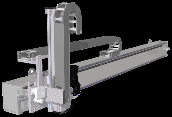
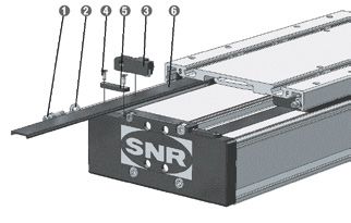
GB 192.8 Assembly of a deflection belt drive on Linear Axis and Linear Tables with screw drive
For the assembling of a deflection belt drive on Linear Axis with screw drive of the series AXC, AXF, AXDL and AXLT, the following
steps in accordance to Figure 3.15 must be observed:
1. Mount the housing for the deflection belt drive 1 in the desired position on the Linear Axis with the fastening screws 2 .
2. Insert the toothed belt disc 4 with the clamping hub 3 on the shaft of the Linear Axis and tight the screws with the required
tightening torque from Table 3.6.
3. Tighten the fastening screws 11 oft he drive adapter 10 slightly.
4. Fasten the drive 6 with the screws 7 on the drive adapter 10 .
5. Insert the toothed belt disc 9 with the clamping hub 3 on the shaft of the drive and tight the screws with the required
tightening torque from Table 3.6.
6. Insert toothed belt 5 .
7. Toothed belt tension (Consider the permissible load capacity of the drive shaft, if necessary reduce the toothed belt tension
and proportionally the drive torque):
a. By the torque
Fasten the tensioning plate with the oiled tensioning screw 12 on the drive adapter 10 . Tight the tensioning screw 12 with
the required tightening torque from Table 3.5. Take account of the rating of the drive shaft, if necessary reducing the torque.
b. By a frequency measuring device TOOLSPBELTPRO-SW (ID Number 372992)
Fasten the tensioning plate with the oiled tensioning screw 12 on the drive adapter 10 . Tight the tensioning screw 12 .
Attach the toothed belt with a metal pin and measure the eigenfrequency with a frequency measuring device (accout the
user manual). When the values from Table 3.5 are reached, the correct toothed belt tension is achived.
c. By the NTN-SNR measuring device for the toothed belt tension
Assemble the measuring device on the drive adapter 10 . Tighten the tensioning screw until the value from Table 3.5 is reached.
8. Tight the fastening screws 11 of the drive adapter 10 with the required tightening torque (when using the NTN-SNR measuring
device, remove these and close the deflection belt drive with the tensioning plate and the tensioning screw).
9. Close the deflection belt drive with the cover 13 .
Figure 3.15___ Assembly deflection belt drive
GB 20Table 3.5_____ Parameter deflection belt drives
Distance motor
Pretension force flange - Maximum prmissible
on the measuring Pretension force Torque center toothed belt drive torque
Series Type Version device 1 on the toothed belt Eigenfrequenzy 2 tensioning screw 3 discdrive (permanent torque) 4
[N] [N] [Hz] [Nm] [mm] [Nm]
SN1605 100 50 149 0,2 1,8
SV1605 130 65 170 0,3 2,6
SN1610 170 85 194 0,4 3,5
AXC60 SV1610 250 125 236 0,5 18 5,3
SN1616 270 135 245 0,6 5,6
T_1604 140 70 176 0,3 3,0
T_1608 210 105 216 0,5 4,5
SN2005 100 50 68 0,2 2,1
SV2005 160 80 85 0,3 3,7
SN2020 350 175 126 0,8 8,3
AXC80 SV2020 630 315 170 1,4 21 15,0 (11,0)
SN2050 630 315 170 1,4 15,0
T_2004 190 95 93 0,4 4,3
AXC T_2008 260 130 109 0,6 6,0
SN2505 210 105 98 0,5 4,8
SN2510 400 200 135 0,9 9,5
SN2525 630 315 170 1,4 15,0 (11,0)
AXC100 SN2550 630 315 170 1,4 21 15,0
TN2405 420 210 138 0,9 10,0
TN2410 590 295 164 1,3 14,0
SN3205 150 75 54 0,4 5,6
SN3210 290 145 74 0,9 11,0
SV3210 290 145 74 0,9 11,0
AXC120 SN3220 580 290 105 1,7 30 22,0
SN3232 630 315 110 1,9 24,0
T_3606 630 315 98 1,5 19,0
T_3612 500 250 110 1,9 24,0
SN2505 210 105 98 0,5 4,8
SN2510 400 200 135 0,9 9,5
AXF100_-D SN2525 630 315 170 1,4 21 15,0 (11,0)
SN2550 630 315 170 1,4 15,0
AXF TN2405 420 210 138 0,9 10,0
TN2405 190 95 93 0,4 4,3
GN2020 240 120 105 0,5 5,7
AXF100_-P GN2060 550 275 158 1,2 21 13,0
GN2090 630 315 170 1,4 15,0
SN1605 100 50 149 0,2 1,1
SN1610 110 55 156 0,2 2,3
AXDL110 SN1616 170 85 194 0,4 18 3,6
TN1604 100 50 149 0,2 1,9
TN1608 140 70 176 0,3 2,9
SN2505 110 55 71 0,2 2,5
SN2510 210 105 98 0,5 4,9
SN2525 510 255 153 1,1 12,0 (11,0)
AXDL160 SN2550 630 315 170 1,4 21 15,0
AXDL
TN2405 260 130 109 0,6 6,0
TN2410 380 190 132 0,8 9,0
SN3205 170 85 57 0,5 6,4
SN3210 350 175 82 1,0 13,0
SN3220 630 315 110 1,9 24,0
AXDL240 SN3232 630 315 110 1,9 30 24,0
TN3606 580 290 105 1,7 22,0
TN3612 630 315 110 1,9 24,0
SN2005 210 105 163 0,5 4,3
SN2020 460 230 241 1,0 10,0
AXLT155 TN2004 330 165 204 0,7 21
7,0
TN2008 460 230 241 1,0 9,8
SN2505 230 115 102 0,5 5,4
SN2510 470 235 146 1,0 11,0
SN2525 630 315 170 1,4 15,0 (11,0)
AXDL225 SN2550 630 315 170 1,4 21 15,0
TN2405 420 210 138 0,9 10,0
TN2410 590 295 164 1,3 14,0
AXLT SN3205 290 145 74 0,9 11,0
SN3210 550 275 103 1,6 21,0
SN3220 630 315 110 1,9 24,0
AXDL325 SN3232 630 315 110 1,9 30 24,0
TN3606 630 315 110 1,9 24,0
TN3612 630 315 110 1,9 24,0
SN4005 260 130 30 0,8 16,0
SN4010 600 300 45 1,8 38,0
AXDL455 SN4020 1 200 600 64 3,6 45 76,0
SN4040 1 650 825 75 4,9 105,0
TN4007 700 350 49 2,1 44
1
NTN-SNR measuring device for the toothed belt tensioning 3
Value results in a toothed belt tensioning force with 25% safety
2
Toothed belt tensioning by a frequency measunring device 4
Maximum permittet drive torque = Table value / ratio
Table 3.6_____ Tightening torques clamping hub
Diameter drive shaft [mm] ≤6 ≤ 14 > 14
Fastening torque clamping ring [Nm] 2 5 10
GB 213. Maintenance and lubrication
3.1 General information
Caution!
All maintenance and service works must be carried out in power off and secured stage.
The motor housing can reach high temperatures during operation.
3.2 Lubrication
For the reliable operation of the Linear Axis, a sufficient lubrication is essential.
The lubrication should ensure a lubricant film (oil film) between rolling elements and raceways of the guiding and drive elements to
prevent wear and premature fatigue of the components.
In addition, the metallic surfaces are protected against corrosion. Furthermore, the lubricant film allows a smooth sliding of the seals
on the surfaces and reduces also the wear of them.
Insufficient lubrication not only increases the wear, it reduces also significantly the life time.
An optimal selection of the lubricant has a decisive influence on the function and life time of the Linear Axis. In order for the function of
the system to be not affected and remain over a long period lubricated according to the environmental conditions; specific requirements
should be defined.
Such environmental conditions and factors may be for example:
• High or low temperature
• Condensation and splash water effects
• Radiation exposure
• High vibration stress
• Use under vacuum conditions and/or in clean rooms
• Applying of special substances (for example, vapors, acids, etc.)
• High acceleration and velocity
• Continually short stroke movement (< 2 x carriage length)
• Dirt and dust
3.3 Lubricants
There are several types of situational lubricants for the different guiding and drive systems of the Linear Axis.
The lubricants have the following functions:
• Reduction of the friction
• Reduction of the starting moment
• Protection against wear
• Corrosion protection
• Noise reduction
Linear guides and ball screws
Lithium soap greases with the marking KP2-K according to DIN 51825 and NLGI class 2 according to DIN 51818 with EP additives
are to be used under normal conditions.
Specific requirements under special environmental conditions require the selection of a corresponding suitable grease.
In general the compatibility of the lubricants must be checked with each other or with the corrosion protection oil.
Table 4.1 provides an overview of the lubricants used by NTN-SNR for linear guides and ball screws. The use of greases containing
solid additives (for example, graphite or MoS2) is not allowed.
GB 22Table 4.1_____ Lubricants for linear guides and ball screws
Description Base oil / NLGI- Worked Basic oil viscosity Density [mg/ Propertie Application area
Type of classe penetration DIN 51562 at cm3]
soap DIN51818 DIN ISO 2137 at 40°C [mm2/s]
25°C [0,1mm]
SNR LUB Mineral oil / 2 295 ca. 115 890 Very high protection against • High temperature range
HEAVY DUTY Lithium with EP additives wear and corrosion • High loads
SNR LUB Esther, SHC / Lithium, 2 - 25 900 Very good adhesion properties, • High velocity
HIGH SPEED+ Calcium Very good water resistance • Low temperature
SNR LUB semi-synthetic oil / 2 265...295 160 900 High temperature resistance, • High temperature range
HIGH TEMP Polyurea Good corrosion protection,
High oxidation resistance
SNR LUB FOOD Paraffinic mineral oil, 2 265...295 195 920 Good corrosion protection, • Food processing industry
PAO / Aluminum Very good adhesion properties,
complex High water resistance,
NSF H1 registered*
Microlube GL261 Mineral oil / special 1 310...340 280 890 Good wearing protection, • High temperature range
lithium-calcium soap Particularly pressure-resistant, • High loads
Additive against tribocorrosion • Short-stroke application
• Vibrations
Klübersynth Synthetic 2 265...295 ca. 30 890 Particularly pressure-resistant, • Clean room application
BEM34-32 hydrocarbon oil / special Good wearing protection,
calcium soap Good ageing resistance,
Low starting torque
Klübersynth Synthetic 1 310...340 ca.150 920 Good corrosion protection, • Food processing industry
UH1 14-151 hydrocarbon Good ageing resistance, • Pharmaceutical industry
oil / ester oil High water resistance,
Aluminum complex soap NSF H1 registered*
* This lubricant has been registered as an H1 product, i.e. it was developed for occasional, technically unavoidable contact with food. Experience
has shown that the lubricant can also be used for appropriate applications in the pharmaceutical and cosmetic industry when the conditions in the
product information are adhered to. However, no specific test results that might be required for applications in the pharmaceutical industry, e.g.
bio-compatibility, are available. The systems manufacturer and operator should therefore perform appropriate risk analyses before applications in
this area. Measures to exclude health risks and injuries have to be taken, where required. (Source: Klüber Lubrication)
GB 23Track roller guides
The hardened steel shafts and the rollers of the track roller guides are oil lubricated under normal conditions. The lubricating oils have
to correspondi to the specification ISO VG460. NTN-SNR usees as standard oil Shell Omala 460. Table 4.2 provides an overview of
the lubricanting oils used by NTN-SNR for track roller guides.
Table 4.2_____ Lubricating oils for track roller guides
Kinematic
viscosity DIN51562 Density Temperature range
Description Type of oil Properties Application range
at 40°C [g/cm3] [°C]
[mm2/s]
Good ageing and Good ageing and
temperature stability, good temperature stability,
corrosion good corrosion protection
Shell Omala Mineral oils and
460 904 -10…+90°C protection properties properties General machine
460 additives.
construction
Good ageing and wear Pharmaceutical industry,
Klüberoil 4 protection, NSF H1 food industry
Polyalphaolefin film 460 860 -30…+120°C registered*
UH1-460N
Trapezoidal screw
For trapezoidal screws is the use of the same lubricants as for linear guides and ball screws is possible. Greases containing solid
additives (for example, graphite or MoS2) can be used in the series AXC, AXF and AXLT. The ingress of these lubricants into the
carriages is to be prevented.
Rack and pinion drive
The rack and pinion drive is optimally supplied with lubricant by a permanent lubrication system in combination with a felt rack-wheel.
The system is filled with the lubricant SNR LUB HEAVY DUTY. It can also be used for special versions with different lubricants.
3.4 Lubrication methods
NTN-SNR Linear Axis can be supplied with lubricant by manual grease gun, automatic lubricators or central lubrication systems.
3.4.1 Manual grease guns
When using manual grease guns (Figure 4.1), the guiding and drive elements of the Linear Axis are lubricated by the mounted grease
nipple.
Figure 4.1____ NTN-SNR Manual grease gun
GB 243.4.2 Automatic electro-mechanical lubricator
DRIVE BOOSTER
An automatic lubricator allows constant and regular lubrication of
the drive elements of the Linear Axis. Automatic electro-mechanical
lubricators are at NTN-SNR Linear Axis suitable and in use only
for the lubrication of the rack and pinion drive. The lubricator type
DRIVE BOOSTER 120 (Figure 4.2) is used here. The lubricators can
be supplied with different kinds of grease or oil and are available
for selection in addition to the standard grease SNR LUB HEAVY
DUTY with the grease SNR LUB FOOD and the oil SNR FOOD
CHAIN OIL.
Figure 4.2____ A
utomatic electro-mechanical lubricator
DRIVE BOOSTER 120
On request the automatic electro-mechanical lubricator DRIVE BOOSTER can also be delivered with the filling quantities 60cc and 250 cc.
For more information please contact our NTN-SNR application engineers.
3.4.3 Central lubrication system
NTN-SNR Linear Axis can be supplied on request with a connection
for a central lubrication system.
A suitable central lubrication system is the CONTROL BOOSTER
(Figure 4.3). The CONTROL BOOSTER has six connectors for
lubricant lines, which can be configured individually and can be
optionally be equipped with 250 cc and 500 cc volume of lubricant
in the CONTROL REFILL unit. The CONTROL REFILL unit can be
after emptying replaced or be factory-provided refilled.
Figure 4.3____ CONTROL BOOSTER
For more information please contact our NTN-SNR application engineers.
GB 253.5 Lubrication points
NTN-SNR Linear Axis has depending on the series a different
number of lubrication points in different positions.
AXC / AXF Series
The Linear Axis of the AXC and AXF series are equipped on
both sides with grease nipples to guarantee the best possible
access. This means that per lubrication interval, the amounts of the
lubricant indicated in Chaper 4.6 may be introduced only on one
side of the axis in the appropriate grease nipple. The lubrication
points (Figure 4.4) are marked with «F» for the linear or track roller
guide and «S» for the screw. As grease nipples are depending
on the size cup head or hydraulic type grease nipple mounted.
For the toothed belt axis the lubrication point «S» is omitted.
For Linear Axis of the AXF series with the guiding system P
and the drive version Z or GN are the guiding system and the
drive maintenance-free and does not have a mounted lubrication
connection.
Figure 4.4____ Lubrication points AXC / AXF
AXDL Series
Linear Axis of AXDL series are equipped at both front sides of
the slider unit with grease nipples, to guarantee the best possible
access. This means that per lubrication interval, the amounts of
the lubricant indicated in Chaper 4.6 may be introduced only
on one front side of the axis in the appropriate grease nipple.
For Linear Axis with screw drive the lubrication points (Figure
4.5) are marked with "F" for the linear or track roller guide on this
side and with "S" for the screw drive and the linear or track roller
guide on the other side. The lubrication points for Linear Axis with
toothed belt drive have no marking. As grease nipples are cup
head grease nipples mounted.
Figure 4.5____ Lubrication poinrs AXDL
AXBG Series
Linear Axis of the series AXBG have per carriage one grease nipple
(Figure 4.6). By this grease nipple, the guiding system is supplied
with lubricant. For lubrication of the ball screw with the lubricant
is applied directly to the ball screw. The amounts of the lubricant
are specified in Chaper 4.6. For the versions with one carriage, the
grease nipple is mounted as standard on the floating bearing side,
but can also be exchanged on the fixed bearing side. For versions
with two carriages the grease nipples are arranged respectively
on the bearing side. Depending on the size, ball type or hydraulic
type grease nipple can be mounted.
Figure 4.6____ Lubrication point AXBG
GB 26AXLT Series
The Linear Axis of the AXLT series have separate lubrication points
for each carriage and for the screw drive. These are arranged on
both sides of the slider unit (Figure 4.7). The lubrication points are
marked with "F" for the linear guide and "S" for the screw drive.
Per lubrication interval the amounts of the lubricant indicated in
Chaper 4.6 have to be introduced in each of the four carriages
and in the screw drive individually.
Figure 4.7____ Lubrication points AXLT
AXS Series (Lifting and Gantry Axis)
For Lifting and Gantry Axis of the series AXS the amounts of the
lubricant per lubrication interval indicated in Chaper 4.6 and have
to be indicated in each of the four carriages (Figure 4.8). Linear Axis
with rack and pinion drive are equipped with automatic lubricators
for the toothed rack, which must be activated during start-up.
Figure 4.8____ Lubrication points for AXS Lifting and Gantry axis
AXS Series (Telescopic axis)
For Telescopic Axis of the AXS series (Figure 4.9) the different
guiding levels must be considered separately. In the first guiding
level, the amounts of lubricant specified in Chaper 4.6 are per
lubrication interval indicated individually to each of the four
carriages. In the second guiding level the amounts of lubricant
specified in the maintenance manual are to be indicated only
on one side of the table into the two existing lubrication points.
An exception is the AXS280T, where all four carriages in the second
guiding level have to be relubricated individually. The rack drive is
equipped with an automatic lubricator, which must be activated
during start-up.
Figure 4.9____ L
ubrication points and automatic lubricator for AXS
Teleskopic axis
AXLM Series
The Linear Axis of the AXLM series have separate lubrication points
for each carriage. These are arranged on front sides or lateral of
the end plate from the carriages (Figure 4.10).
Per lubrication interval the amounts of the lubricant indicated
in Chaper 4.6 have to be introduced in each of the carriages
individually.
Figure 4.10___ Lubrication points AXLM
GB 27You can also read