Coordination within the remote sensing payload on the Solar Orbiter mission
←
→
Page content transcription
If your browser does not render page correctly, please read the page content below
A&A 642, A6 (2020)
https://doi.org/10.1051/0004-6361/201937032                                                                                                              Astronomy
c F. Auchère et al. 2020                                                                                                                                  &
                                                                                                                                                         Astrophysics
The Solar Orbiter mission                                                                                                                                     Special issue

      Coordination within the remote sensing payload on the Solar
                            Orbiter mission
 F. Auchère1 , V. Andretta13 , E. Antonucci2 , N. Bach12 , M. Battaglia5 , A. Bemporad2 , D. Berghmans9 , E. Buchlin1 ,
   S. Caminade1 , M. Carlsson25 , J. Carlyle6 , J. J. Cerullo31 , P. C. Chamberlin11 , R.C. Colaninno4 , J. M. Davila11 ,
       A. De Groof12 , L. Etesi5 , S. Fahmy6 , S. Fineschi2 , A. Fludra3 , H. R. Gilbert11 , A. Giunta3 , T. Grundy3 ,
    M. Haberreiter22 , L. K. Harra22,32 , D. M. Hassler10 , J. Hirzberger8 , R. A. Howard4 , G. Hurford14 , L. Kleint5 ,
       M. Kolleck8 , S. Krucker5 , A. Lagg8 , F. Landini26 , D. M. Long21 , J. Lefort12 , S. Lodiot23 , B. Mampaey9 ,
 S. Maloney30 , F. Marliani6 , V. Martinez-Pillet27 , D. R. McMullin17 , D. Müller6 , G. Nicolini2 , D. Orozco Suarez18 ,
       A. Pacros6 , M. Pancrazzi20 , S. Parenti1,9 , H. Peter8 , A. Philippon1 , S. Plunkett33 , N. Rich4 , P. Rochus7 ,
A. Rouillard24 , M. Romoli20 , L. Sanchez12 , U. Schühle8 , S. Sidher3 , S. K. Solanki8,29 , D. Spadaro16 , O. C. St Cyr11 ,
    T. Straus13 , I. Tanco23 , L. Teriaca8 , W. T. Thompson19 , J. C. del Toro Iniesta18 , C. Verbeeck9 , A. Vourlidas15 ,
            C. Watson12 , T. Wiegelmann8 , D. Williams12 , J. Woch8 , A. N. Zhukov9,28 , and I. Zouganelis12
                                                             (Affiliations can be found after the references)

                                                       Received 31 October 2019 / Accepted 22 January 2020

                                                                                    ABSTRACT

Context. To meet the scientific objectives of the mission, the Solar Orbiter spacecraft carries a suite of in-situ (IS) and remote sensing (RS)
instruments designed for joint operations with inter-instrument communication capabilities. Indeed, previous missions have shown that the Sun
(imaged by the RS instruments) and the heliosphere (mainly sampled by the IS instruments) should be considered as an integrated system rather
than separate entities. Many of the advances expected from Solar Orbiter rely on this synergistic approach between IS and RS measurements.
Aims. Many aspects of hardware development, integration, testing, and operations are common to two or more RS instruments. In this paper, we
describe the coordination effort initiated from the early mission phases by the Remote Sensing Working Group. We review the scientific goals and
challenges, and give an overview of the technical solutions devised to successfully operate these instruments together.
Methods. A major constraint for the RS instruments is the limited telemetry (TM) bandwidth of the Solar Orbiter deep-space mission compared
to missions in Earth orbit. Hence, many of the strategies developed to maximise the scientific return from these instruments revolve around
the optimisation of TM usage, relying for example on onboard autonomy for data processing, compression, and selection for downlink. The
planning process itself has been optimised to alleviate the dynamic nature of the targets, and an inter-instrument communication scheme has been
implemented which can be used to autonomously alter the observing modes. We also outline the plans for in-flight cross-calibration, which will
be essential to the joint data reduction and analysis.
Results. The RS instrument package on Solar Orbiter will carry out comprehensive measurements from the solar interior to the inner heliosphere.
Thanks to the close coordination between the instrument teams and the European Space Agency, several challenges specific to the RS suite were
identified and addressed in a timely manner.
Key words. space vehicles: instruments – Sun: general – instrumentation: polarimeters – instrumentation: spectrographs – telescopes

1. The remote sensing challenge                                                                 try (TM) rate varies greatly along a given orbit and from orbit
                                                                                                to orbit (Müller et al. 2020), and as a result it is highly con-
Due to its comprehensive payload and unique mission profile,                                    strained compared to recent missions in Earth orbit, such as
Solar Orbiter is very different from previous solar and helio-                                  for example Hinode (Kosugi et al. 2007) and the Solar Dynam-
spheric missions. The top-level scientific objectives of the mis-                               ics Observatory (SDO, Pesnell et al. 2012). While this is a con-
sion (Müller et al. 2013; Müller et al. 2020) require close inter-                              straint for the full Solar Orbiter payload, it is felt more strongly
action between the different instruments. This has motivated the                                by the RS instruments since they are inherently capable of
formation of the Remote Sensing Working Group (RSWG) and                                        producing orders of magnitude more data than can be trans-
the in-situ Working Group (Walsh et al. 2020) in charge of coor-                                ferred to the ground. As a mitigation, the RS science opera-
dinating the science operations of the remote sensing (RS) and                                  tions have been restricted – from the early mission studies – to
in-situ (IS) instruments, respectively. Initially, the two work-                                three ten-day Remote Sensing Windows (RSW) per six-month
ing groups were mostly devoted to hardware and spacecraft                                       orbit, centred on the a priori most interesting vantage points:
(S/C) interface developments, topics that justified the distinction                             the perihelion and the two extreme solar latitudes. As a result,
between RS and IS instruments. As the hardware development                                      the RS suite will not continuously observe the solar activity as
progressed, the two groups worked on joint operations within the                                has been the case for previous missions. However, when possi-
activities of the Science Operations Working Group (SOWG).                                      ble, these nominal periods of operation will be complemented
    The Solar Orbiter mission profile poses several challenges                                  by continuous low-cadence, synoptic type observations outside
for the RS instruments. As a deep space mission, the teleme-                                    the RSWs (see Sect. 4) providing contextual information to the
                                                                                                                                                                            A6, page 1 of 12

               Open Access article, published by EDP Sciences, under the terms of the Creative Commons Attribution License (https://creativecommons.org/licenses/by/4.0),
                                which permits unrestricted use, distribution, and reproduction in any medium, provided the original work is properly cited.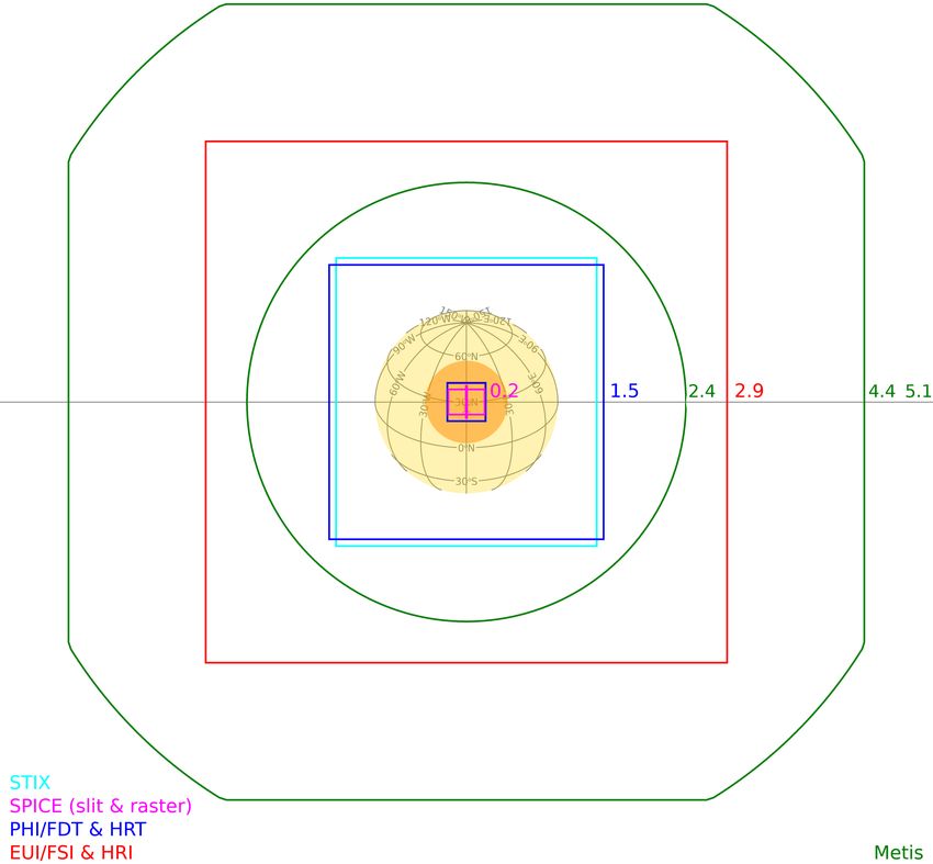
A&A 642, A6 (2020)
IS payload and other observatories (e.g. Parker Solar Probe,
Fox et al. 2016).
TM (Gbits)
Allocated
Because each orbit is different, the planning concept includes
1.8
53
27
53
53
45
a selection of scientific objectives to be addressed by the payload
during the next orbit, typically six months before the start of each
six-month planning period. Thus, the high-level science plan-
raster 1.5–8 h
5–30 min (2)
stare 5–60 s
5–30 min
0.1–10 s
cadence
ning for each instrument must be finalised several months before
Typical
≥1 min
≥1 min
10 min
30 min
1–10 s
1s
the actual observations. The detailed commanding is frozen two
weeks before observations, with modifications only possible a
few days before if they are resource-neutral (e.g. TM, power)
resolution resolution
1–15 keV
for S/C safety reasons. Combined with the limited duration of
Angular Spectral
0.01 nm
0.01 nm
0.04 nm
0.04 nm
the RSWs and limited TM, this was identified very early on as
–
–
–
–
–
–
a major hurdle for the observation of intermittent events, such
as prominence eruptions, coronal mass ejections (CMEs), and
flares. Section 2.2 discusses the strategies devised to overcome
≤2000
≥8000
00
4.200
900
100
100
700
100
700
4.2
10
these difficulties.
The main characteristics of the six RS instruments are sum-
marised in Table 1. Details can be found in the respective instru-
3.8◦ × 3.8◦ square 17.4 and 30.4 nm
Notes. TM allocations are per orbit. (1) Metis outer FOV ±2.9◦ square vignetted by a 3.4◦ circle. (2) Metis cadence 1–20 s for fluctuation studies.
energy range
Wavelength/
580–640 nm
500–850 nm
ment papers given as references. The RS instruments fields
97–105 nm
4–150 keV
70–79 nm
121.6 nm
121.6 nm
617.3 nm
617.3 nm
17.4 nm
of view (FOVs) are illustrated in Fig. 1 for four cases. The
S/C is nominally pointed at Sun center (Figs. 1a,c, and d),
the nominal roll angle defined by the S/C Z-axis being per-
pendicular to the orbital plane. The SPectral Imaging of the
Coronal Environment (SPICE) and the high-resolution channels
16.80 × 16.80 square
16.50 × 16.50 square
17.00 × 17.00 square
40◦ × 38.5◦ square
(1)
(1)
2◦ × 2◦ circular
of the Extreme Ultraviolet Imager (EUI) and the Polarimetric
0
160 × 11−140
1.6◦ −2.9◦ /3.4◦
1.6◦ −2.9◦ /3.4◦
16 × 11−14
1.9◦ × 2.1◦
and Helioseismic Imager (PHI) will be able to observe non-
FOV
Sun-centered targets by off-pointing the S/C (Fig. 1b) within
the range allowed by the Metis coronagraph safety constraint
0
(Sect. 2.3 and Antonucci et al. 2020). The S/C boresight can
be pointed anywhere on the solar disc, for example towards
Channel /
the solar limb (which allows EUI/HRI174 , EUI/HRILyα , and
detector
HRILyα
HRI174
HRT
FDT
SW
LW
FSI
UV
VL
SPICE to perform limited off-limb observations). As detailed in
–
–
Sect. 2.3, limb-pointing is not compatible with Metis observa-
tions at close Sun distances. Unlike previous solar physics mis-
High-resolution and wide field images of the solar disc and corona
Metis (Antonucci et al. 2020) Images of the solar corona in polarised white light and in the HI
Raw data: full-disc and high-resolution polarimetrically modulated
narrow-band filtergrams; onboard processed data: continuum inten-
sities, vector magnetic fields and line-of-sight velocities in the pho-
Imaging spectroscopy of solar flare thermal and non-thermal X-
sions, the distance to the Sun will vary by about a factor of two
between perihelion and high-latitude windows (Figs. 1a and b).
Combined with the changing solar latitude (e.g. Figs. 1a and d),
this will result in a variety of geometric configurations. The dif- SPICE (SPICE Consortium High-resolution spectroscopy of the solar disc and corona.
ferent scientific objectives will be prioritised accordingly.
Table 1. Main characteristics of the Solar Orbiter remote-sensing instruments.
The top-level scientific objectives are translated into different
operational profiles for the various instruments. For example, at
SoloHI (Howard et al. 2020) White light images of the extended corona.
closest approach, EUI and PHI will provide very-high-resolution
images (0.2800 equivalent from Earth) and are capable of observ-
ing at high cadence (down to sub-second). To reduce their
downlink volume, these instruments are capable of data selec-
tion and extensive onboard processing, by including internal
memory equivalent to or larger than their TM orbit alloca-
tion. On the other hand, SPICE will perform little onboard
data selection or processing, but flexibility of operation comes
in the UV / EUV.
from the large parameter space offered by it being a spec-
Measurements
Lyman α line.
trograph. Conversely, the Spectrometer/Telescope for Imaging
X-rays (STIX) and the Solar orbiter Heliospheric Imager
tosphere.
(SoloHI) have been designed to mostly provide observations of
rays.
synoptic type.
STIX (Krucker et al. 2020)
EUI (Rochus et al. 2020)
PHI (Solanki et al. 2020)
2. Remote sensing windows and planning
2.1. Planning strategy
Name (reference)
As most Solar Orbiter objectives require consistent data sets
across the full science payload, the instrument observations
must be planned in a coordinated way. This is achieved through
2020)
the concept of Solar Orbiter Observing Plans (SOOPs, see
Zouganelis et al. 2020). These are coordinated campaigns of
A6, page 2 of 12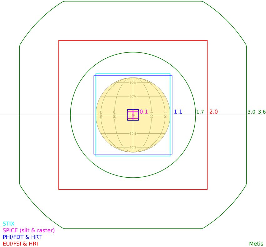
F. Auchère et al.: Coordination within the remote sensing payload on the Solar Orbiter mission

                                      (a)                                                                 (b)

                                (c)                                                                        (d)

Fig. 1. Fields of view (FOVs) of the remote-sensing instruments in various orbital configurations and distances from the Sun. The extents of the
FOVs are labelled in solar radii. The PHI/HRT, EUI/HRI174 , and EUI/HRILyα FOVs are completely overlapping. In the cases where off-points are
limited by the Metis safety constraint, the area on the solar disc within which off-pointing is allowed is highlighted in orange (see e.g. (d)). (a)
Closest perihelion at 0.28 AU, disc centre pointing. (b) Off-point to solar pole, at 0.6 AU, S/C rolled 10◦ with respect to solar north. (c) All RS
FOVs, incl. SoloHI, at 0.3 AU perihelion. (d) Maximum latitude case (30◦ N), at 0.4 AU.

several (if not all) instruments adjusting their observation modes         network User Group meetings. There are several levels of Solar
and parameters to serve one common science objective. Solar                Orbiter planning cycles (Sanchez et al., in prep.), as summarised
Orbiter’s mission level and long-term planning will be per-                here:
formed at a SOOP level rather than on the level of individ-                     1. Mission Level Planning (MLP): the Solar Orbiter Science
ual instrument commands. Once the common campaigns have                    Working Team (SWT) defines top-level science activities for the
been scheduled and the involvement of each instrument defined,             entire mission (Science Activity Plan, SAP), as well as detailed
the shorter-term planning will start consolidating the command             science goals for each orbit.
timeline for each instrument based on the agreed plan. The                      2. Long Term Planning (LTP): given input from the SWT,
SOOP concept will be especially relevant for the RS payload as             the SOWG defines a coherent mission-level observing plan for
most instruments have many different observation modes which               a given orbit after ground station allocation has been fixed; it is
typically vary significantly in data output depending on the sci-          assisted by the Science Operations Centre (SOC) at the Euro-
ence goal being addressed.                                                 pean Space Astronomy Centre (ESAC), Madrid, which provides
    Mission planning is driven by the six-month planning peri-             detailed information on the resources available. Science activi-
ods after each of the European Space TRACKing (ESTRACK)                    ties defined in the SAP are translated into SOOPs for a six-month

                                                                                                                                  A6, page 3 of 12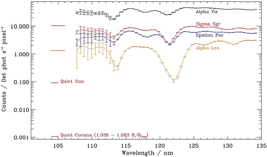
A&A 642, A6 (2020)

period (∼1 orbit), planned at least six months before the start of     multi-instrument eruption observations. In appropriate observa-
the period. A SOOP is a collection of instrument operations that       tion campaigns, the S/C pointing can be updated up to 3 days
belong together, i.e., that serve a common science goal.               before the observations. This is similar in timescale to the
    3. Medium Term Planning (MTP): the instrument teams                Hinode case which usually finalises pointings two days in
translate the SOOPs for a six-month period into Instrument             advance. Analysis of prior synoptic data from other sources is
Operations Requests (IORs), which provide details about all            key to the success of capturing eruptions. An example which
telecommands (TC) that will be sent to the S/C. The MTP                has been extensively used by several missions is the Max Mil-
is completed at least 4 weeks before execution, and fixes S/C          lenium program that issues Major Flare Watches based on
resources, instrument modes, and default pointing.                     solar data across the electromagnetic spectrum to assess the
    4. Short Term Planning (STP): this cycle covers 1 week and         probability of a large solar flare. Missions like Hinode replan
is planned approximately 1 week before execution. This is the          observations based on a Major Flare Watch, which has been
last opportunity to modify instrument operation modes. It gener-       effective. Bloomfield et al. (2016) describes the success rate of
ates detailed schedules of commands for S/C and payload.               this process. Several instruments have data trigger mechanisms
    5. Very Short Term Planning (VSTP): this will be sched-            that autonomously identify which data sets contain eruptions
uled for a subset of RSWs only (agreed in the LTP) and allows          (Sect. 3), as was successfully demonstrated for the Sun-Earth
updates to the S/C fine pointing (pVSTP) and/or limited updates        Connections Coronal and Heliospheric Investigation (SECCHI,
of the instrument observations (iVSTP). Update requests are            Howard et al. 2008) suite of instruments on the Solar-TErrestrial
possible once every 24 hours, and the time between the request         RElations Observatory (STEREO, Kaiser et al. 2008) mission.
and the execution is no less than 3 days.                              Some instruments can overwrite data which did not emanate
                                                                       from trigger events. All instruments can receive and communi-
                                                                       cate to such identifications onboard.
2.2. “Hunting” for the “big event”
                                                                           The means of communication between instruments is
Two of the four overarching science questions for Solar Orbiter        described in Sect. 3. Three instruments have triggers in their
(Müller et al. 2013) explicitly depend on observations of solar        onboard systems. The EUI has a flare trigger responding to inten-
eruptions; namely:                                                     sity enhancements in EUI/FSI; STIX has a flare trigger respond-
    – How do solar transients drive heliospheric variability?          ing to flares in the X-ray; and Metis has a CME trigger that
    – How do solar eruptions produce energetic particle radiation      responds to enhancements in white light emission off-limb. All
that fills the heliosphere?                                            instruments can share their coordinates and timings of the events
    The RS instruments will address these questions by return-         and respond appropriately. One example of a response could be
ing observations of the source regions and early phases of the         to prioritise these data for download. It is important to remem-
eruptions, whose interplanetary effects will be sampled by the         ber that the three triggers respond to different parts of the solar
IS instruments, at least for some eruptions. However, obtaining        atmosphere and hence the response times will be different – and
comprehensive observations of major eruptions with the RS pay-         indeed all three instruments may not respond to the same event.
load is challenging for two reasons:
    – Temporally: the RSWs comprise only one-sixth of the total        2.3. Pointing strategy
orbit, meaning that about five-sixths of the eruptions will be
missed. In addition, there is insufficient TM allocation for high-     The whole RS payload is co-pointed and the four high-resolution
resolution instruments like EUI and PHI to operate throughout          telescopes (EUI/HRI174 , EUI/HRILyα , PHI/HRT, SPICE) cover
the RSWs with a sufficient imaging cadence.                            only part of the solar disc even when far from the Sun (Fig. 1d).
    – Spatially: the FOVs of EUI/HRI174 , EUI/HRILyα ,                 Fulfilment of several of the Solar Orbiter scientific objectives
PHI/HRT, and SPICE cover an area 7 (at 0.6 AU) to 31 (at               thus requires that the S/C be off-pointed to the relevant targets.
0.28 AU) times smaller than the full solar disc, indicating a high     For example, the S/C will have to track active regions consid-
likelihood that, with pre-defined pointing, many eruptions will        ered likely to produce major events to maximise the chances
be missed. This is not a concern for the wide FOV telescopes           of observing large eruptions with the high-resolution telescopes
(STIX, Metis, SoloHI, EUI/FSI and PHI/FDT).                            (see Sect. 2.2). Pointing at the poles is required for SPICE
    Clearly, catching eruptions “by chance” with the high-             Doppler measurements of the fast wind outflows from the polar
resolution telescopes of Solar Orbiter is very unlikely, even over     coronal holes (SPICE Consortium 2020), or PHI measurements
the full mission lifetime. A study of the Hinode space mission         of the polar magnetic field strength and seismic diagnostics of
flare catalogue carried out by Watanabe et al. (2012) found that       the subsurface flows (Solanki et al. 2020). Coordinated obser-
the two narrow FOV instruments on the mission observed
F. Auchère et al.: Coordination within the remote sensing payload on the Solar Orbiter mission
whenever the S/C points further than 0.1 R at 0.28 AU linearly In turn, EUI will listen to flags broadcast by STIX and Metis.
up to 1 R at 0.51 AU, which is the S/C off-pointing capabil- It will combine the information from these two instruments with
ity limit. For example, the orange disc in Fig. 1d marks the its own event detection using simple logic (e.g. STIX sees a flare
Metis safety limit at 0.4 AU. Off-points larger than its safety limit and EUI sees a flare in the same region) to prioritise its data.
will result in Metis being closed, thus preventing joint observa- Also, EUI is planning on using the PHI jitter information for
tions with the other instruments. This may be mitigated by Metis data prioritisation.
observations right before and after the off-point manoeuvres.
3.2. The CME-detection algorithm of Metis and actions
3. Inter-instrument communication (Service 20) based on inter-instrument communication content
An inter-instrument communication (IIC) service has been The Metis CME-detection algorithm monitors the total inten-
established on Solar Orbiter to allow instruments to cross-share sity in eight sectors nominally aligned to the instrument frame
a limited set of parameters, summarised in Table 2. The IIC is of reference. Metis will run its event detection on difference
implemented through the use of a dedicated TM packet that each images of the same polariser position. The algorithm is based
instrument sends to the computer (OBC) with a fixed cadence. on that implemented on SECCHI, COR2 (Howard et al. 2008).
All received parameter data are gathered in one data pool. These The COR2 algorithm uses macro-pixels and total brightness
are extended with extra parameters based on S/C events (like images computed onboard from double exposures. As for the
pointing information) and are then communicated back from the other instruments, the detection parameters will need to be fine-
OBC to the instruments through the so-called Service 20 TC tuned in flight and the effect of the varying angular size of the
packets. This service will mainly be used to pass on event detec- Sun (size of the FOV with respect to the solar disc size) on the
tion flags which may sequentially trigger actions in the receiv- detection needs to be assessed. This is particularly relevant for
ing instruments to safeguard or prioritise data which are likely to Metis as the range in heliocentric distance covered by the Metis
include a solar event. In addition, Service 20 packets will include FOV varies with the S/C-Sun distance. For example, Metis will
an instrument-level heartbeat that can be used to identify stale raise its CME-event flag higher in the corona when the S/C is
data. The service is available to all payloads, but due to the dif- at 0.5 AU than when it is at 0.28 AU. In addition, the stray-light
ferent nature of IS compared to RS instruments and the time pattern may also vary.
delays between activity observed on the Sun and its character- In addition to its own detection algorithm, Metis can also
istics measured in-situ, each group of instruments will typically react to the EUI and STIX flags. In particular, Metis will lis-
only react to triggers from its own group. ten to off-limb events detected by EUI/FSI304 and on-disc flares
The RS instruments have agreed to generate IIC TM packets detected by STIX. The reaction thresholds to those flags are pro-
at a cadence of 1 Hz. The only exceptions are SPICE and SoloHI grammable and will be fine-tuned in flight. Moreover, a time
which currently do not plan to participate in this inter-instrument delay can be set for the Metis reaction to those on-disc or near-
communications mechanism, but will keep the capability to use disc events to account for the CME transit time through the inner
Service 20 in the future. The STIX, Metis, and EUI plan to region of the solar corona up to the inner edge of the Metis FOV.
broadcast event flag information, which is detailed in the para- Once a CME flag is activated, either internal or external, the
graphs below. The PHI will share S/C jitter information based detection of an event will make Metis switch to its special CME
on its automatic Image Stabilisation System (ISS, Solanki et al. observing mode.
2020). The S/C-provided parameters will also include informa-
tion on pointing stability (e.g. on the occurrence of non-planned
thruster firings) and will allow instruments to assign low priori- 3.3. The detection algorithm of the Polarimetric and
ties to images taken during these events. Helioseismic Imager and actions based on
inter-instrument communication content
3.1. The detection algorithm of the Extreme Ultraviolet The PHI will provide four parameters containing the S/C point-
Imager and actions based on inter-instrument ing stability obtained from the correlation functions of the PHI
communication content ISS (Solanki et al. 2020). During dedicated RSWs, PHI will lis-
ten to the STIX flare trigger for possible white light flares. If
The EUI will run detection algorithms on the images gener- triggered, PHI will autonomously switch to a special science
ated by FSI in both wavelengths. It will broadcast, both for operation mode tailored to obtain high-cadence continuum
EUI/FSI304 and EUI/FSI174 , whether an event has been detected, images in the 617.3 nm spectral range interlaced with magne-
the time and location (with respect to the instrument boresight) tograms. In addition, PHI will read from the data pool of infor-
of the detection, and a rough estimate of the brightness of the mation provided by S/C on its stability, PHI’s heat rejecting
event. The detection algorithm is based on the SoFast activity entrance windows, and the instrument doors. Science images that
detector1 (Bonte et al. 2013). It uses thresholds on macropixels are acquired during times where Service 20 data indicates non-
and a set of rules to minimise the number of false detections. It nominal pointing accuracy will be marked.
must be noted however that due to the limited space in the mem-
ory of EUI and its automated onboard data management, an EUI
detection does not necessarily mean the EUI images make it to 3.4. The detection algorithm of STIX and actions based on
the ground. If later a more significant event is detected, it may inter-instrument communication content
potentially overwrite the earlier ones. Also, the detection param-
eters will need to be adjusted in-flight to take into account the The STIX will use a dedicated sub-collimator (grid) to detect
properties of the real data, and any effects, for example those flares and broadcast the corresponding information to indicate
caused by the varying size of the Sun. the current level and location of solar activity with 1 arcmin loca-
tion accuracy. The flag will be updated no more frequently than
1
http://sidc.be/sofast once every 4 or 8 s (configurable by TC). The latency will also
A6, page 5 of 12A&A 642, A6 (2020)
Table 2. Summary of inter-instrument communications between the RS instruments.
Instrument Broadcasts Reacts to
EUI FSI events timing and location STIX and Metis flags and PHI jitter data
Metis CME timing and location EUI and STIX flags
PHI S/C pointing stability STIX flags
SoloHI – –
SPICE – –
STIX X-ray flares timing and location –
Notes. See Sect. 3 for details.
Table 3. Synoptic observations planned outside the nominal Remote via the SOOP mechanism (Sect. 2.1). The latter implies accurate
Sensing Windows. co-alignment between the various telescopes and is discussed in
Sect. 5.2. Moreover, the quantitative analysis requires a reliable
Instrument Observations/data products Data volume inter-instrument relative radiometric calibration during flight as
the various instruments will age and deviate differently from the
EUI 15 min cadence EUI/FSI174 4.2 ground calibration (Sect. 5.3).
Metis 30 min cadence visible light 6.9
PHI Daily Full Sun BLOS and con- 3.3
tinuum images 5.1. Remote sensing checkout windows
SoloHI 30 min cadence 2.5◦ wide equa- 3.2
torial and latitudinal swaths Unlike previous RS platforms for the observation of the Sun, the
SPICE Daily First Ionisation Potential 3.4 first science observations will take place at the end of a Cruise
bias map Phase (CP) lasting 1.8 years. Furthermore, the commissioning
STIX Nominal operations (Table 1) 33 activities performed during the first months of the mission will not
test the instruments in an environment representative of the ther-
Notes. The data volume is given as a percentage of each instrument’s mal and radiation conditions of the perihelia. It will therefore be
TM allocation. necessary to monitor the instrument health and behaviour during
the CP to ensure their optimal performance at the start of the Nom-
be 4 or 8 s, as configured. The STIX will not read or react to mes- inal Mission Phase (NMP). For this purpose, four remote sensing
sages from other instruments; there is no need to do so because checkout windows (RSCWs) have been planned through the CP.
of its mono-mode observing and post-facto data selection. Each of these windows lasts a few days during which each instru-
ment will characterise its response to the changing environment.
In addition, coordinated observation campaigns will take place to
4. Out-of-RSW observations monitor the relative pointing of the instruments (Sect. 5.2).
The nominal strategy of RS windows centred on the perihelia
and maximum latitudes maximises the scientific return of the 5.2. Co-alignment among RS instruments
mission during these unique moments, but also implies that the
connection between the RS and the IS observations is effec- Telescope co-alignment requires the determination of three
tive only during one-sixth of the mission duration. In order to angles (pitch, yaw, and roll) for each telescope defining the devi-
increase the duration of the joint observations, the RSWG inves- ation from a common reference frame. The choice of reference
tigated the possibility for the RS instruments to dedicate a frac- frame is not important for the following discussion (it could be
tion of their TM allocation to perform synoptic “out-of-RSW” the S/C reference frame), but for clarity we can assume that it
observations that will provide the contextual information neces- is centred on the S/C, with the roll axis pointing towards Sun
sary to enable connection science throughout orbits, while main- center. In addition, co-registration requires the knowledge of the
taining a low-resource/low-impact profile and avoid violating the plate scale for each detector, and eventually the knowledge of
Electro-Magnetic Compatibility (EMC) requirements of the IS the optical distortion across the FOV. The instruments have been
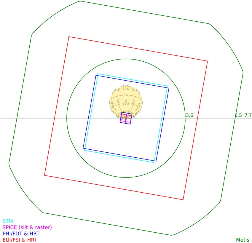
instruments. co-aligned on the ground during S/C integration so that the lines
It was found that, while added late into the development of of sight of the high-resolution channels will be in flight within
the mission ground segment, out-of-RSW observations could be the specified two-arcminute cone (Fig. 2). The values take into
made almost resource neutral for the ground operations teams as account the measurements of the instrument lines of sight with
long as they fit into the low-latency data volume (Sect. 6). Each respect to their reference cubes, the relative orientations of all
RS instrument therefore designed a “synoptic” type program that the reference cubes, the measurement errors, and the modelled
can be run continuously to provide basic contextual information thermo-elastic distortions. While this ensures sufficient overlap
(Table 3) without impacting their core objectives. of the FOVs, the lines of sight are expected to move within that
cone due to the changing thermal environment, thus requiring
regular monitoring of the relative orientations of the telescopes.
5. Inter-calibration
In-flight verification of the relative pointing of the instruments
Achieving the Solar Orbiter science objectives relies on the close will be performed several times during CP. Although they will
coordination between the RS instruments. This requires that the not cover the full range of temperatures encountered during the
data from the various RS instruments be directly comparable in NMP, these tests will allow correlation with the thermal models
terms of temporal and spatial localisation. The former is ensured of the instruments.
A6, page 6 of 12F. Auchère et al.: Coordination within the remote sensing payload on the Solar Orbiter mission
This does not apply to FSI because the altitude of the limb at
extreme ultraviolet (EUV) wavelengths is not accurately known.
Roll manoeuvres can be used to determine the aspect ratio of the
pixels and thus the isotropy of the plate scale.
The STIX is a full Sun instrument but limb fitting cannot be
used with X-ray images. The instrument is however equipped
with an internal optical system able to determine the instrument
pointing with respect to Sun centre (by a type of analogue limb
fitting) to a precision of 4 arcsec (Krucker et al. 2020).
While constant monitoring of the direction of Sun centre
is possible by limb fitting, the method is insensitive to the roll
angle, which therefore has to be determined from observations of
stars or planets (Sect. 5.2.1). Finally, the pointing of EUI/HRI174 ,
EUI/HRILyα , and SPICE may be determined from limb observa-
tions made during S/C off-points and comparison with simulta-
neous FSI images. A similar comparison between PHI/HRT and
PHI/FDT will be made difficult by the time required for thermal
stabilisation of PHI/HRT following a PHI/FDT observation.
Fig. 2. Estimated worst-case co-registration configuration of the high-
resolution fields of view based on the pre-flight measurements (in 5.2.3. Cross-correlation
arcsec). All known sources of misalignment, both internal and exter-
nal to the instruments, are included. The two horizontal bars in the Cross-correlation can provide the relative plate scale and the
SPICE FOV are the co-registration dumbbells at the ends of the three angles necessary to co-register the data from two instru-
slit (SPICE Consortium 2020). ments. Therefore, for the instruments that do not routinely see
stars or the solar limb, the pointing with respect to the common
reference frame can be obtained by cross-correlation with one
that does, provided that their passbands are similar or correlate
5.2.1. Using stars and planets well with each other. Due to their very similar passbands, it is
Stars and planets provide a reliable reference with which to deter- possible to cross-correlate nearly simultaneous EUI/HRI174 and
mine all the co-alignment parameters. SoloHI and the VL channel EUI/FSI174 images to a high accuracy (typically 0.1 FSI pixel,
of Metis will observe stars in all their images and their orientation i.e. 0.45 arcsec). Likewise, the EUI/HRILyα images can be co-
can be determined accurately with respect to the reference frame aligned to a similar accuracy with the EUI/FSI304 as the two
from the S/C orbital position. This is also true of the Metis ultra- bands are highly correlated (Gordino et al. 2020).
violet (UV) channel that will be able to detect stars with signifi- The pointing of PHI/HRT with respect to PHI/FDT was mea-
cant emission around 121.6 nm, when such stars are present in the sured on the ground (see Solanki et al. 2020, this volume). How-
FOV. These bright UV stars will also be visible in the VL channel. ever, the switch between the two telescopes requires a thermal
Tracking of stars across the FOVs can also be used to derive the settling time that is estimated to be of the order of hours (to
plate scale and optical distortion (Thernisien et al. 2006). Simi- be confirmed during flight). Thus, the repeatability of relative
larly, two transits of Mercury in front of the corona (in January pointing of the two telescopes will be known only after the
2023 and May 2027 at about 1.7 and 1.1 R , respectively) will be first two checkout windows. PHI/HRT images cannot be cross-
observable by FSI. These events may become grazing or disc tran- correlated against PHI/FDT ones since the two channels do not
sits depending on the exact launch date and trajectory, in which image simultaneously.
case they would also be observable by PHI/FDT and the high- The images taken by PHI/HRT may however be correlated
resolution telescopes (SPICE, EUI/HRI174 , EUI/HRILyα ). They against SPICE raster images. The C i continuum around 102–
will provide unique opportunities to determine the pointing, roll 104 nm is formed low enough in the atmosphere (above the tem-
(Couvidat et al. 2016), plate scale (Auchère & Artzner 2004), and perature minimum, at a height of around 1000 km according to
distortion for these instruments. Aside from these rare opportuni- Vernazza et al. 1981) that images in this spectral emission should
ties, these telescopes will have to rely on other means to monitor cross-correlate quite well with maps of the absolute longitudinal
their pointing. field (see Fig. 3).
The pointing of SPICE itself can be determined by cross-
correlating Lyman β rasters with EUI/HRILyα images (see, e.g.
5.2.2. Solar limb fitting Fig. 2 of Tian et al. 2009), or 102.8 nm Fe x and 77.0 nm Ne viii
Since the solar disc will always be visible in the PHI/FDT rasters with images from EUI/HRI174 . Since both spectral chan-
and FSI FOVs, the position of Sun center can be determined nels are fed by the same slit, co-aligning the two channels con-
to sub-pixel accuracy by fitting the limb (e.g. Auchère et al. sists of identifying the end points of the slit on the detector for
1998, 2000). For FSI, a better precision will be achieved in each channel.
EUI/FSI174 because the limb is sharper at 17.4 nm than at Table 4 summarises the methods used to co-align the various
30.4 nm (Auchère et al. 1998; Defise et al. 1999). EUI/FSI304 is instruments.
co-aligned by design with EUI/FSI174 as the switch between one
and the other occurs by swapping filters without optical power. 5.3. Photometric inter-instrument calibration
Offpoint manoeuvres can be used to determine the plate scale
of these instruments (Auchère et al. 2000) provided that the S/C It is predicted that relative cross calibration of the RS instru-
attitude is known to a sufficient accuracy. For PHI, the plate ments will be difficult because of the quasi absence of com-
scale can also be obtained relative to the photospheric diameter. mon lines or passbands between the instruments. Observation of
A6, page 7 of 12A&A 642, A6 (2020)
(e.g. the quiet Sun) with high uncertainties or against other
instruments that can be more closely monitored. For instance,
the EUI EUI/FSI304 could be checked against the Metis Lyman α
channel, since their FOVs overlap significantly (Fig. 1).
5.4. Calibration stability
Keeping throughout the mission the calibration that has been
achieved during ground calibration campaigns is a major under-
taking that is intimately related to the cleanliness of the S/C.
The RS instruments with their optical components are exposed
to solar UV irradiation, which contributes to degradation due to
polymerisation when organic material is deposited on them. This
Fig. 3. Left: rastered (east to west) image of the quiet Sun obtained with degradation is strongly wavelength dependent. Particular empha-
the SUMER spectrograph aboard SOHO in the C i continuum around sis was therefore put on the molecular cleanliness of the pay-
104 nm. Right: line of sight magnetogram of the same area taken by the
load and S/C during design and build activities. The cleanliness
MDI instrument aboard SOHO. Data are clipped to the −85 to +85 G
range. The magnetogram was acquired around the time SUMER com- requirements of the payload instruments were established very
pleted the 13 minutes scan, on 17 April 2009 around 09:38 UTC. early in the program and manifested as interface requirements
to be fulfilled by instruments and S/C. All activities needed to
minimise particulate and molecular contamination were carried
bright FUV stars (e.g. hot O and B stars) can be effectively used throughout Assembly, Verification, and Validation (AIV) pro-
to cross-calibrate EUI and Metis at Lyman α. The same stars cesses (García-Marirrodriga et al. 2020). For example, all flight
appear to be bright enough to also be detected by the SPICE- hardware went through a bake-out process and the fully assem-
LW channel. Since the EUI or EUI/HRILyα observations of stars bled S/C was finally subjected to a vacuum-thermal cycling
can be made only during offpoints, the Metis door will have to and out-gassing process with monitoring and verification of the
be closed when these observations are made below 0.55 AU. In cleanliness with unprecedented accuracy. In addition, the S/C
these cases, the stars will be observed by Metis before and/or carries a purge gas distribution system to supply all payloads
after off-points, provided enough time for repointing to disc cen- with clean gas during all ground activities, including transport,
tre before the end of the transit through the Metis FOV. It is up to launch. Some activities to minimise molecular contamina-
possible for EUI/HRI174 and EUI/FSI174 to be cross-calibrated tion have been implemented by design and they have impact on
with SPICE using the 102.8 nm line of Fe x. Cross calibration the operations of the payload:
of EUI/FSI304 and EUI/HRILyα may be more problematic, as – Heat Shield doors. All RS instruments but SoloHI have
SPICE only observes Lyman β. their apertures passing through openings in the Heat Shield.
The most effective way to monitor the radiometric response With the exception of STIX, each opening has its own door
of instruments in space is by comparing them to stable and well- mechanism activating a shield that can open and close the aper-
known calibration sources such as calibration rocket flights and tures individually. Such a shield will reduce UV exposure of the
onboard calibration lamps. As the former are not foreseen and instrument’s first optical surfaces during non-operational phases
the latter are not included in any of the instruments, the only of the flight. During the commissioning phase, Heat Shield doors
possibility is to use natural sources. can be opened at the request of each instrument. During coordi-
For visible-light instruments, the task is performed easily nated observations, the doors must be opened well in advance to
either against the solar quiet photosphere (PHI) or against ref- achieve thermal equilibrium.
erence stars (Metis VL and SoloHI). Monitoring the radiomet- – Instrument doors (SPICE, EUI). In addition to Heat Shield
ric response of instruments becomes more difficult for shorter doors, the UV instruments SPICE and EUI have their own aper-
wavelengths. Instruments detecting radiation above the hydro- ture door mechanisms that allow them to open and close the
gen absorption edge can be calibrated against bright B and A aperture at any time. These doors shall stay closed during any
main sequence stars as they provide stable and intense flux at period of long non-operational phases. The doors are designed
wavelengths above 100 nm (Mihalas & Binney 1981). A discus- with a motor drive mechanism and a sliding door, closing the
sion on several UV stars suitable for calibration can be found in instrument aperture with a minimal gap such that no UV light
Snow et al. (2013). Figure 4 shows the spectrum of α Virginis, can enter. The three EUI telescopes each have a door mecha-
which has substantial emission down to 100 nm. Figure 5 shows nism, and the door of the EUI/FSI carries a circular shield that
that bright UV stars should be easily detectable with the SPICE can be placed in the aperture in such a way as to occult the solar
spectrograph. A similar result is expected for the EUI/HRILyα disc, enabling FSI to be used as a quasi-coronagraphic imager.
telescope while equivalent calculations show the same also for The doors keep the instruments closed during ground activities.
the Metis UV channel. α Leo and σ Sgr are particularly use- They allow the maintainance of a small overpressure provided
ful as they are occulted a few times by the solar disc during the by continuous purging with clean gas. The doors remain closed
cruise phase, and the nominal and extended mission phases. during the first phases of the mission to prevent any ingress of
A further check is provided by observing the H i Lyman α contamination. They will be opened when it has been verified
(EUI/HRILyα ) over Lyman β (SPICE) ratio in the quiet Sun. by the Contamination Monitoring System (CMS) that molecular
This ratio is remarkably constant, particularly in the regions deposition at the apertures is low enough and the risk of molec-
with lower magnetic flux (Tian et al. 2009). The situation is ular contamination is minimal.
more complex for the EUV instrumentation, namely EUI/FSI – Contamination Monitoring System. The Contamination
and EUI/HRI174 , as any stellar signal in the EUV is too faint to Monitoring System consists of two thermally controlled quartz
be detectable. The radiometric throughput of these channels can crystal micro-balances (QCM) that are powered and operated
only be checked relative to the average values in selected regions by the SPICE instrument. One is located next to the SPICE
A6, page 8 of 12F. Auchère et al.: Coordination within the remote sensing payload on the Solar Orbiter mission
Table 4. Inter-instrument spatial co-alignment matrix.
Common reference EUI EUI/HRI174 EUI EUI/HRILyα PHI/HRT
frame
PHI/FDT Limb fitting
Planet transit
Metis VL stars
Planet transit
UV stars
SoloHI Stars, planets
EUI FSI Limb fit (174) Cross corr. of Cross corr of 304
174 images images
Planet transit
SPICE H i, Fe x, Ne viii Cross corr. with Corr. C i scans
scans vs. 304 and Lyman β scans with BLOS maps
174 images
Fig. 5. Detected photons per second per pixel expected by the SPICE
spectrograph for the displayed UV stars. The calculations assume that
all the flux entering the telescope, after accounting for the SPICE effec-
Fig. 4. Spectra of α Vir as observed by EURD (λ < 107 nm) and IUE tive area, ends up in one pixel. More realistically, these values should be
(λ > 116 nm), superposed on the Kurucz model (heavy line) scaled divided by ten. The expected levels for the quiet Sun disc emission and
to IUE data. Figure taken from Morales et al. (2000), reproduced with for the emission expected in the quiet corona above the limb are also
permission. shown for comparison.
aperture door (CMS1) while the other is mounted next to the the feedthroughs between the Heat Shield and the instrument
SWA-HIS instrument (CMS2) behind the Heat Shield. The two aperture. These windows prevent contaminants and UV radiation
QCMs measure the deposition of condensable material from the entering the optical system of PHI. The SPICE primary mirror
environment. They serve as a diagnostic tool to assist in the carries only a very thin reflective coating of 10 nm in thickness
planning of opening the protective doors and to characterise to reflect the vacuum-ultraviolet range of SPICE while it trans-
the out-gassing of the S/C during the mission. mits most of the infrared and visible spectral range heating the
– Protective devices: Metis protection cap, PHI entrance fil- mirror. Whenever the SPICE aperture is open, the instrument’s
ter, SPICE mirror and ion deflector, and SoloHI door. In order to ion deflector must be operational, with a high voltage applied
minimise the particle contamination during ground and launch to the plates that will deflect charged solar wind particles from
activities, an ejectable sealing cap is mounted at the Metis their path towards the primary mirror. The SoloHI door covers
entrance aperture behind the Heat Shield door. The sealing cap the baffle area of the instrument during ground operations. It pro-
ejection system is a one-shot mechanism that will release and tects the sensitive baffle edges from accidental damage and dust
eject the protection cap. It is planned to be operated at the very from accumulating on the baffles. The door opening mechanism
beginning of the mission. After the ejection, the Metis aper- is a one-time actuation, and is released after launch when the
ture remains open and the Heat Shield door is fundamental for contamination level is sufficiently low.
the safety of the Metis instrument as it must be closed when
the S/C is pointing off Sun center, since the coronagraph is 6. Low-latency data
designed specifically to operate in Sun-centred position. The
two apertures of the PHI instrument have no extra door mecha- As explained in Sanchez et al. (in prep.), scientific data gen-
nism because they are protected by the Heat Rejection Entrance erated onboard are assigned different downlink priorities. The
Windows, which are spectral interference filters mounted inside need to define a set of high-priority data became clear when
A6, page 9 of 12A&A 642, A6 (2020)
simulations of the fill state of the onboard Solid State Mass It is therefore crucial for the scientific outcome of the mission,
Memory (SSMM) revealed that the maximum capacity of the and for the whole scientific community, to make the full range of
SSMM will likely be reached several times during the mission, Solar Orbiter data easily accessible and interpretable by defining
resulting in high data latencies. data products that are consistently formatted in a transparent and
In order to minimise the effect of data latency on the instru- standard manner. To this end, standard metadata keywords have
ment operations planning and performance checks, a minimal been agreed upon for both FITS and CDF data files produced by
set of so-called low-latency (LL) data has been defined for each Solar Orbiter (MADAWG 2018).
instrument. The LL daily volume has been necessarily restricted The Solar Orbiter metadata standard for FITS files fol-
to 1 MB per instrument (2 MB in exceptional cases), to guaran- lows the FITS standard, combined with the World Coordinate
tee that it can be downlinked at each S/C contact, even at times System (WCS) standard for coordinates defined in a series of
of poor communications links (at the far side of the Sun, close papers (Greisen & Calabretta 2002; Calabretta & Greisen 2002;
to 2 AU from Earth) and taking into account that S/C and instru- Greisen et al. 2006; Rots et al. 2015), and adapted for solar coor-
ment housekeeping data (HK) will be brought down first. The dinates (Thompson 2006). Where possible, keywords already in
LL dataset fulfils three use cases: common use by other missions (STEREO, PROBA2 (PRoject
1. It allows basic checks of instrument performance and sci- for On-Board Autonomy), Hinode, IRIS (Interface Region Imag-
ence data quality (i.e. avoids the up to six-month delay in assess- ing Spectrograph), etc.) were adopted to maximise cross-mission
ing instrument performance). compatibility, and enable the use of Solar Orbiter data in already
2. It allows data selection for those instruments with onboard existing tools such as (J)Helioviewer (Müller et al. 2017). In
data buffers or can help (re-)prioritise data in instrument internal some cases, the evolving FITS standard necessitated a deviation
memories. from common practice. For example, the keywords XPOSURE
3. It allows the pointing profile to be readjusted and/or re- and TELAPSE were adopted in place of the older EXPTIME key-
targeted when tracking solar features. word to be compatible with the WCS time standard (Rots et al.
A special use case of remote-sensing LL data is the precursor 2015). Not all keywords in the Solar Orbiter metadata standard
dataset that will be acquired before the start of some RSWs. are required to appear in every FITS header, as some are only
As described in Sanchez et al. (in prep.), several mission sci- appropriate for certain kinds of data. However, when these key-
ence objectives that require RS observations make it necessary words are used, they must conform to the definition in the meta-
to perform precursor observations before the start RS windows data standard. A complete list of adopted keywords is given
to enable the SOC to choose an optimal fine-pointing profile for in Table 6. Along with basic FITS files, the metadata standard
the S/C that is commensurate with the pre-planned science activ- also includes support for IMAGE and binary table (BINTABLE)
ity (related to LL use case 3 defined above). As this requires a extensions.
fast turn-around time between data acquisition and S/C pointing A function of the Solar Orbiter metadata standard is to doc-
updates, the data will be downlinked as part of the daily TM dump. ument the context in which the data were taken. This includes
Table 5 lists the sets of low-latency data that have been defined standardised keywords regarding the instrument configuration
for the RS payload. The numbers between square brackets refer during the observation, such as FILTER for the name of any
to the use cases defined above. The table shows that in general bandpass filter used, or NSUMEXP for the number of exposures
the low-latency concepts adopted by RS instruments are more summed together onboard to form the observation (in this latter
complex and less continuous than the approach of the in-situ case, the keyword XPOSURE is the total effective exposure time
instruments (see Walsh et al. 2020). This is partly due to the non- of all the exposures added together). The SOOP associated with
continuous way of operating, and the variety of science goals the observation is identified through the keywords SOOPNAME,
assigned to the RS windows. For most instruments, the LL data SOOPTYPE, OBS_ID which gives the ID number of the SOOP,
volume and/or content is likely to vary over the mission and con- and TARGET which identifies the SOOP target (e.g. “AR”, “QS”,
tains data which are specifically designed for the LL data stream. “limb”, etc.). We note that the keyword OBJECT has a similar
Nevertheless, at all times, the LL data need to fit in the small TM definition, but is tied to the instrument configuration at the time,
allocation to guarantee prompt retrieval. It must be noted that as a and not to the SOOP.
consequence of the extreme compression factors and/or low time Use of the WCS formalism allows the data to be completely
resolution, the RS LL data may be unsuitable for scientific anal- specified in terms of both pointing and observation time, together
ysis. However, they are of high operational value; for example, with the units for both the data themselves and the coordinates
for the evaluation of the conditions on the Sun on the far-side of in which they are specified. Other keywords specify the position
Earth, the choice of the best target for the high-resolution instru- of the S/C at the time of the observation in a variety of coor-
ments, the assessment of instrument performance and data qual- dinate systems (Thompson 2006). For example, the keywords
ity, and for providing optimal onboard data management. CRLN_OBS, CRLT_OBS, DSUN_OBS can be used to express the
position of the S/C in Carrington Heliographic longitude and lat-
7. Common FITS headers content itude, along with the distance from Sun centre, while HCIX_OBS,
HCIY_OBS, HCIZ_OBS express the x, y, z Heliocentric Inertial
Solar Orbiter science data are organised into two categories: (HCI) coordinates. The S/C velocity can be expressed with the
– remote sensing images and spectra which are stored in the keywords HCIX_VOB, HCIY_VOB, HCIZ_VOB, with HCI explicitly
Flexible Image Transfer Standard (FITS; Pence et al. 2010) for- chosen as it is an inertial system. The WCS formalism allows for
mat widely used within the astronomical community; alternative coordinate systems to be defined in the header along
– and in-situ and radio data which are stored in the Common with the primary coordinate system. For example, SoloHI may
Data Format (CDF; Goucher et al. 1994) used by the particles choose to add a celestial coordinate system to characterise the
and fields communities. locations of stars and planets visible in their FOV.
Most Solar Orbiter science goals are based on coordinated The information contained in Solar Orbiter FITS head-
analysis between multiple instruments, and depend on interoper- ers depends on the data level. In general, complete metadata,
ability between these two quite distinct scientific communities. including S/C attitude, are only available beginning with Level 2
A6, page 10 of 12F. Auchère et al.: Coordination within the remote sensing payload on the Solar Orbiter mission
Table 5. Low-latency data products provided by the Remote-Sensing payload.
Instr. Type of data product [use case(s)] Cadence
EUI Beacon data: low-resolution FSI images (174/304 Å) [2,3] 30 min
Synoptic data: low-cadence, high-quality FSI images [1] 1 set/day
If applicable: sample EUI/HRI174 & EUI/HRILyα data [1,3] 1 set/day
PHI Precursor and quicklook data: 1024 × 1024 pixels continuum image & LOS-magnetogram [all*] 1 set/day (∗∗)
Calibration: snapshot of calibration products [1] Start/end RSW
SPICE Each science study is preceded by LL version with same scientific performance [1] Varying
SoloHI Regular set of horizontal strips to build “J-maps” [3] TBD
Compressed sample of detectors or regions of interest [1]
Metis 2 VL images for total brightness + 1 UV image (all rebinned) [1] 1 set/day
8 light curves, one for each VL sector
STIX Light curves per energy band [all (∗) ] 4s
Flare information data [all (∗) ] 8s
Energy calibration spectra [1]
Notes. The use case(s) that each of the data sets fulfill (Sect. 6) are marked between brackets. (∗) PHI and STIX implement data selection onboard
but only from an internal buffer, not from SSMM. (∗∗) PHI will usually provide full-disc data; in case PHI/FDT is not in operation for more than
one day; PHI/HRT data will be provided instead.
Table 6. Agreed FITS keywords. in that only preliminary calibrations have been applied. During
times of low downlink performance, low-latency data may be the
Basic only data available for several months. In this case instrument
teams may choose to produce an enhanced version of the low-
SIMPLE, BITPIX, NAXIS, NAXISi, EXTEND, latency data with better calibration and more complete metadata
LONGSTRN, BSCALE, BZERO, BTYPE, BUNIT, in the header, which would then qualify as L2 data or above.
DATAMIN, DATAMAX, BLANK, COMMENT, CHECKSUM,
DATASUM, HISTORY, XTENSION, PCOUNT, GCOUNT,
EXTNAME, TFIELDS, TFORMi, TTYPEi, TUNITi, 8. Summary
TDIMi, END The RS instrument package of Solar Orbiter will provide us
General description with a new view of our Sun, from its interior out to the solar
FILENAME, FILE_RAW, PARENT, APID, DATE, wind. Some of their measurements will be unprecedented, like
DATE-OBS, DATE-BEG, DATE-AVG, DATE-END, the highest-ever resolution UV and EUV images, or observa-
TIMESYS, TIMRDER, TIMSYER, OBT_BEG, tions of the Sun’s polar regions, including the direct Doppler
OBT_END, LEVEL, ORIGIN, VERS_CAL, VERSION, velocity of the fast solar wind. The development of instruments
SOOPNAME, SOOPTYPE, OBS_ID, TARGET that are prepared to face 13 solar constants has been a challenge
that could only be met by intelligent design and the dedication of
Instrument and observation configuration the teams. The coordination effort led by the RSWG contributed
OBSRVTRY, TELESCOP, INSTRUME, DETECTOR, to the optimisation of the instruments’ performance and of the
OBJECT, OBS_MODE, STUDY_ID, FILTER, joint operation schemes in the context of the overall mission
WAVELNTH, WAVEMIN, WAVEMAX, WAVEBAND, objectives.
XPOSURE, NSUMEXP, TELAPSE,TRIGGERD, PXBEGn,
PXENDn, NBINi, NBIN, COMPRESS, COMPQUAL Acknowledgements. A. V. is supported by NRL grant N00173-16-1-G029. D.
WCS attitude parameters M. L. is grateful to the Science Technology and Facilities Council for the award
of an Ernest Rutherford Fellowship (ST/R003246/1).
WCSAXES, WCSNAME, CTYPEi, CUNITi, PC j_i,
CDELTi, CROTA, CRVALi, CRPIXi, CRDERi,
CSYERi, LONPOLE, SPECSYS, VELOSYS References
Solar ephemeris data Antonucci, E., Romoli, M., Andretta, V., et al. 2020, A&A, 642, A10 (Solar
Orbiter SI)
RSUN_ARC, RSUN_REF, SOLAR_B0, SOLAR_P0, Auchère, F., & Artzner, G. E. 2004, Sol. Phys., 219, 217
SOLAR_EP, CAR_ROT, HGLT_OBS, HGLN_OBS, Auchère, F., Boulade, S., Koutchmy, S., et al. 1998, A&A, 336, L57
CRLT_OBS, CRLN_OBS, DSUN_OBS, HEEs_OBS, Auchère, F., DeForest, C. E., & Artzner, G. 2000, ApJ, 529, L115
HCIs_OBS, HCIs_VOB, HAEs_OBS, HEQs_OBS, Bloomfield, D. S., Gallagher, P. T., Marquette, W. H., Milligan, R. O., &
Canfield, R. C. 2016, Sol. Phys., 291, 411
GSEs_OBS, OBS_RV, EAR_TDEL, SUN_TIME, Bonte, K., Berghmans, D., De Groof, A., Steed, K., & Poedts, S. 2013, Sol.
DATE_EAR, DATE_SUN Phys., 286, 185
Calabretta, M. R., & Greisen, E. W. 2002, A&A, 395, 1077
Notes. The parameters i and j refer to axis indices, and s can take the Couvidat, S., Schou, J., Hoeksema, J. T., et al. 2016, Sol. Phys., 291, 1887
values X, Y, or Z. Some keywords also have variations for binary tables. Defise, J. M., Clette, F., & Auchère, F. 1999, in EUV, X-Ray, and Gamma-Ray
Complete definitions, including units, are given in MADAWG (2018). Instrumentation for Astronomy X, eds. O. H. Siegmund, & K. A. Flanagan,
Proc. SPIE, 3765, 341
Fox, N. J., Velli, M. C., Bale, S. D., et al. 2016, Space Sci. Rev., 204, 7
(L2). Low-latency files (LL01, LL02, etc.) used for operations García-Marirrodriga, C., Pacros, A., Strandmoe, S., et al. 2020, A&A, in press,
planning differ from their normal science quality equivalents https://doi.org/10.1051/0004-6361/202038519 (Solar Orbiter SI)
A6, page 11 of 12You can also read