Britomart Transport Interchange, Auckland: Alterations and strengthening of the former Chief Post Office
←
→
Page content transcription
If your browser does not render page correctly, please read the page content below
Britomart Transport Interchange, Auckland:
Alterations and strengthening of the former
Chief Post Office

      E.T. Sainsbury and M.L. Gibbs
      Opus International Consultants, Wellington, New Zealand.                       2004 NZSEE
                                                                                     Conference
.

      ABSTRACT: This paper outlines the structural alterations undertaken to transform the
      former Auckland Chief Post Office into the Britomart Station Interchange main entrance
      and ticket hall, including strengthening of the existing building, enclosure of the existing
      lightwell, the addition of a large steel framed “glasshouse” atrium, and lowering of the
      ground floor. The building is relatively large, being 52m x 42m in plan and four storeys
      high, plus a basement. It was built in 1910 with an internal gravity resisting steel frame,
      it originally used the brick walls to resist lateral loads, but with the unreinforced 18m
      high facades and a soft storey effect at the internal atrium, it did not comply with the New
      Zealand Building Code. Strengthening involved the addition of reinforced concrete shear
      walls on the inside of the perimeter walls and the creation of a well connected diaphragm
      at each floor level. As it occupies a prominent site at the foot of Queen Street, and has
      Auckland City Council Heritage classification, strengthening and incorporation into the
      station complex seemed natural. Britomart Station, which is below the CPO, has been
      described in earlier papers. (Fig 1).

1 EXISTING BUILDING

The existing building was built in 1910 as the Auckland Chief Post Office, to the design of J Campbell
Government Architect. The original drawings and specifications still exist and were very useful in
assessing the structure against the current code (NZS 4203:1992).
The ground floor was 1.5m above road level and there are three suspended floors above that, with a
concrete roof surmounted by two large domes. There is also a basement level with limited storey
height.
The building is founded on 12m long concrete piles driven into the Waitemata series rock (weak
siltstone). The reinforced concrete pile caps are tied to the concrete floor slab at basement level and
support massive brick walls, up to 1300mm thick around the perimeter, which support the external
brick walls above. Similar walls provide a base for the columns supporting the three storey atrium.
The riveted steel columns stand on heavy cast iron bases on top of the basement walls, and are framed
into the steel floor and roof beams at the upper levels with elaborate riveted joints. The framing is
generally one way and is not considered to be moment resisting. All the columns are concrete
encased, while the beams are generally unprotected, except for plasterboard linings.
Supporting the kauri timber flooring are jarrah timber floor joists, these were found to be capable of
carrying a live load of 3 kPa despite their spans of up to 7.5m. A weak pumice concrete material
(referred in the original specification as “deafening”) had been poured between the joists to provide a
sound insulating ceiling between floors.
All the steel floor beams were tied into the brickwork with steel rods which passed through their ends,
and the ends of the timber joists were fixed to iron plates built into the brick walls.

                                           Paper Number 26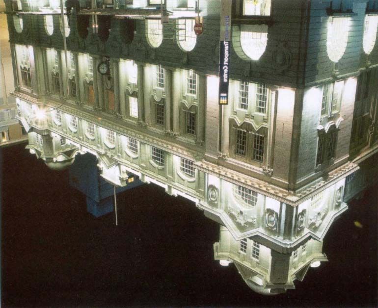
2 PROPOSED END USE

Britomart Station is an underground railway station that services mainly commuter trains, and forms
the centre of Auckland’s Transportation Hub at the foot of Queen Street, adjacent to the Inner
Harbour.
Opus International Consultants Ltd carried out the structural and civil design for these works in close
co-operation with the architectural design team of Mario Madayag and Jasmax.
The architects decision to use the ground floor of the CPO as the ticket hall and entry point for the
station required the majority of the floor to be lowered 1.4m to near ground level. The historic
banking chamber floor was re-established at 0.9m below its original level and 0.5m above the main
floor. The lowered ground floor gave additional height to the ticket hall, more in keeping with its
proposed station use. (Fig 2).
The underground concourse linking the station with Queen Elizabeth Square has a floor level 4.2m
below the new ground floor level, well below sea level.
The original front steps and entry lobby were kept as a separate access to the upper floors, but to date
no firm decision has been taken on the use of the three upper floors.

3 STRENGTHENING OF THE BUILDING

The existing building was found to be lacking in seismic resistance in both directions at all levels.
Large openings at front and rear, to allow for the station ticket hall use and for future light rail trains to
pass through the building, further reduced the seismic resistance of the existing structure.
The building has strong heritage importance with NZHPT Classification A, so that strengthening was
provided to as near as practicable to the current NZ Loadings Code, NZS 4203:1992. This was done
by introducing new reinforced concrete shear walls on the inside of the external walls, with a braced
steel diaphragm at each floor level.
This is a robust solution suitable for the long-term (heritage) situation. The additional mass from the
new concrete walls was about 15% of the total mass, which is within the capacity of the existing
foundations.
The zone factor used for strengthening was 0.5, (based on results of a special study, and making
allowance for the 100 year design life), the risk factor was 1.2 and the ductility factor was 2.0,
(allowing the existing brickwork to contribute to the overall strength of the building); giving an overall
seismic coefficient of 0.22.
An ETABS computer model of the structure was created to evaluate deflections and stresses under this
loading and to compare actions of the existing brick and new concrete walls. To achieve compatibility
of deformation between the two materials while providing long-term protection to the brickwork, the
proportion of load taken by the brickwork was kept to 20%.
The large station access opening in the East wall and the openings in the West wall where heritage
features exist, limited the extent of reinforced concrete walls available at the ground floor level, and
together with the increased height, lead to the adoption of 400mm thick reinforced concrete walls at
this level. On the first floor level the new reinforced shotcrete walls are 200mm thick and on second
and third floors they are 150mm.
The roof is an existing reinforced concrete slab 160mm to 200mm thick, which ties the atrium walls to
the external walls. The roof slab effectively reduces the shear demand on the third floor diaphragm.
The atrium was originally open at roof level, allowing light into the domed roof lights in the ceiling
above the banking chamber at ground floor level. A new steel and glazed roof was placed above the
atrium to protect these heritage features and to provide better control of ventilation.

                                                      2
4 FOUNDATIONS

The original 12m long driven concrete piles pass through about 10 metres of Upper Tauranga Group
(loose volcanic ash/sand) and bear on the upper layers of the Waitemata Group rock, (siltstone), which
has good bearing strength, as borne out by the lack of settlement in the building.
During construction a load test was performed on some of the existing piles, which confirmed their
ultimate capacity was greater than the 800 kN assumed in the design.
It was noted that while the piles lacked significant confining steel, the four 38mm diameter
longitudinal bars and the high quality and strength of the concrete resulted in strong reliable piles.

5 SEISMIC DESIGN APPROACH

The strengthening philosophy was to utilise as much of the strength of the existing materials as
possible, but where this was insufficient, provide additional structure that will be compatible with the
existing.
The building would be changed from using the internal steel framed structure and brick walls into one
in which a concrete perimeter shear wall resists the majority of the seismic loads, with the brick walls
picking up a small proportion. Seismic load from the internal atrium was transferred to the external
walls through the roof and floor diaphragms. (Fig 5 & 6).
The existing brick wall piers, which were incapable of resisting the full design shears, were
strengthened using reinforced concrete walls poured directly on the inside face and connected to the
brickwork using drilled and grouted anchors at close centres. This additional concrete increased the
load on the existing piles and pile caps by about 15% in the worst cases, this was considered
acceptable, and subsequent testing showed that the final pile loads were within their capacities.
Core testing of the brick masonry walls was done and shear values in excess of 1 MPa were found,
which well justified the decision to allow the brickwork to carry 20% of the shear.
The existing concrete roof slab was found to be satisfactory for gravity loads and for seismic shear
loads. This was most useful as it provided a load path for a significant portion of the shear force from
the atrium walls to be taken to the perimeter walls.
The existing timber floors, though well fixed and capable of supporting gravity loads of 3 kPa, were
unable to transfer the seismic design forces by diaphragm action. The timber floors were retained and
the diaphragms were created by using diagonal steel straps in each bay bolted to the steel floor beams
and stabilised by attachment to the underside of the timber joists. (Fig 3).
Eccentricity of loading was large, especially as the front wall was thicker and heavier than the side or
rear walls, and carried the two massive domes at roof level. These eccentric loads were resisted by all
the walls acting together, linked by the diaphragms.
Each wall was considered as a number of piers between windows, linked by spandrel beams. An
ultimate limit state approach was taken to allow each pier to achieve its capacity, with plastic hinges
occurring in the spandrel beams. The restoring moments are thus derived from the shear and flexural
capacities of the spandrel beams as well as from the masses of the wall piers.
The depth of the spandrel beams and the pier widths were limited by the architectural and heritage
requirements. In many cases a deeper beam would have been desirable, but an increase in flexural
capacity would increase the shear demand, so it was necessary to carefully balance all these
requirements.
The architectural requirement to bevel the edges of the walls at openings further reduced the available
space for reinforcing, but contributed to a less obtrusive final product.
A spreadsheet was developed to work out the flexural and shear reinforcement in each beam and pier.
The 150 and 200mm walls at Level 1 and above were limited to 20mm diameter reinforcing to
maintain clearances, but bars up to 32mm diameter were used in the 400mm wall at ground floor level.

                                                   3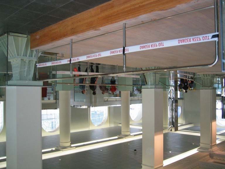
6 LOWERING OF THE GROUND FLOOR

To achieve better access from the adjacent roads it was necessary to lower the ground floor by 1.4m.
In addition, to develop a concourse below the CPO, part of the basement level was lowered by 2.4m to
below mean sea level, requiring control of water inflows. Excavation was designed to be done in bays
using a cement/bentonite cut-off trench, with UC sections built in to provide a temporary wall.
However, the Contractor elected to use a sheet piled cut-off wall, driving the sheet piles within the
limited storey height. Steel flats welded to the tops of the sheet piles and bolt fixed to the existing
basement slab provided restraint to the top of the sheet piles. The excavation was pumped dry and the
water re-injected into the same strata a short distance from the site, in order to meet the resource
consent requirements. Final concrete walls and slabs were poured in the dry.
Lowering the ground floor exposed the existing steel columns, which were supported on the top of the
basement walls, and the architects chose to make a feature of the large cast iron bases of these
columns. However the unreinforced concrete directly beneath the bases had to be confined with new
reinforced concrete plinths. (Fig 4).
Some of the columns were supported at the basement floor level so that when the ground floor was
removed the length of these columns was temporarily increased to 8 metres. As they were concrete
encased over much of their height they retained a high level of axial load capacity, so that additional
stabilising was not needed.

7 CONSTRUCTION ASPECTS

Construction commenced in mid 2002, but inspection of some of the existing materials by the
Contractors revealed the presence of asbestos so that the site had to be isolated and the asbestos
removed before any other operations could be done, causing a delay of two months in the construction
programme.
Once the asbestos had been removed, the work began on the lowering of the ground floor basement
level. During the removal of the asbestos the existing ground floor slab was removed along with the
top portion of the basement walls, to the level of the underside of the new ground floor slab level.
The excavation for the new basement slab extended approximately 0.6m below the underside of the
new base slab. At this point a 500mm thick unreinforced concrete slab was cast to provide a sound
base for the construction of the structural slab and walls and for the Rawell bentonite tanking, which
was placed on top of the unreinforced concrete, and protected by 75mm thick site concrete. The
structural base slab was then cast on top of this layer to the required slab level.
The basement walls were trimmed back around the piles. Formwork was placed in front of the
excavated wall face and site concrete was poured against the ground. Bentonite tanking was nailed to
the site concrete prior to the placement of the wall reinforcing and the walls were then poured in
sequence, to the underside of the new ground floor level.
Reinforced concrete walls were cast on top of the new basement slab up to the underside of the new
ground floor level, these provided support for the new concrete slab which used profiled metal decking
as permanent formwork.
The new perimeter reinforced concrete shear walls were cast against the existing brickwork after
drilling and grouting in closely spaced connecting ties. From basement level to the underside of level
1 the walls were cast using a series of jump forms, as they were 400mm thick, but the upper storey
shear walls were shotcreted in place. Shotcrete was the obvious choice for its ease of placement for
the upper levels, as the thickness there was only 150 to 200mm.
Installation of the steel cross bracing beneath each timber floor level was carried out to form floor
diaphragms to distribute loads to the new reinforced concrete shear walls. The installation was
straight forward, with minor amendments to the details being required in some locations, due to the as-
built construction being different from that which was identified prior to construction.

                                                  4
The new concourse that extends from the new basement level in the CPO across to Queen Elizabeth
Square was constructed predominantly from precast concrete elements. The roof of the concourse,
designed for full traffic loading, was constructed using 300mm thick hollowcore units with a 200mm
thick reinforced concrete topping. The walls were 400mm thick reinforced concrete that was precast
off site.
The concourse excavation was predominantly into fill material and thus done within a sheet pile
cofferdam. As with the basement slab of the CPO, a 500mm thick unreinforced slab was cast as a
working platform and as a means of providing a firm base to build on. Each of the wall panels was
craned into position and the base slab reinforcing placed. The wall panels were connected by the
400mm thick heavily reinforced insitu concrete base slab, which tied the walls into the slab and
provided moment fixity at the joint.
The rear wall of the CPO was one of the final portions of the building to be seismically upgraded.
Large steel columns were bolted to the rear wall around the perimeter of the 20m wide opening as well
as at the locations of the new reinforced concrete columns. A large welded steel truss was connected
to the columns and bolted to the wall to temporarily support the load of the wall above as the opening
was formed.
Four slots were made in the brickwork of the rear wall so that new reinforced concrete columns and
sidewalls could be cast. To support the loads from the new columns, a number of screw piles were
installed in the new reinforced concrete foundation that formed part of the new basement slab. Upon
completion of the columns the remainder of the wall between the columns was removed, and the new
reinforced concrete lintel beam was cast in place to support the wall and its associated loads. Having
constructed the new permanent opening the remainder of the concrete shear walls on levels 1, 2, and 3
along the rear wall were completed and the temporary works removed.
Beams in the rear wall support the steel framed “glass bridge,” which connects the CPO floor to the
lifts, and passes through the “Glasshouse” to the station entry points off Commerce Street. (Gibbs,
Williams 2004).
An existing staircase near the north-eastern corner was removed as part of the refurbishment works.
The walls of the staircase were formed from brick masonry with encased steel columns at each corner.
During the demolition of the walls, one of the columns that was not clearly identified on the original
drawings was exposed and found to have a smaller cross section compared with the rest of the
columns. Because the existing ground floor had been lowered as part of the refurbishment, the
slenderness of this column was increased past the limit of the section to support the full dead and live
load associated with its tributary area. To provide the additional load carrying capacity the steel
column was encased in reinforced concrete to match the appearance of the existing columns.
8 CONCLUSION
The project cost of $30 million covered the strengthening and refurbishing work described here as
well as the construction of the steel framed glasshouse, underground concourse and works associated
with connecting to the new Britomart Station.
The original construction programme, though set back at the start due to the asbestos removal, was not
delayed overall and the lower floors of the building were opened to the public along with the
Britomart Station in July 2003.
Overall the construction proceeded very well with the Contractor following the designers intentions
closely, although several hitches occurred where as-built details did not agree with assumptions made
in the design. The high quality final product reflects the team effort that was made by all parties to the
construction.
The authors recommend that strengthening of old buildings should be kept simple in concept in order
to cope with the inevitable complications that will arise due to previously unforeseen details both
during design and construction.
5REFERENCES:
Maylin and Shanmuganathan (2003): Design and Construction of Britomart Underground Railway Station.
SESOC Journal Vol 16 No1 2003.
Williams and Chalmers (2000): Recent developments in the design of cut and cover railway tunnels and stations.
Conf on railway engineering, RTSA; Proc Adelaide, May 2000.
Williams, Sainsbury, Shanmuganathan, Gibbs (2001): Design of Britomart cut and cover railway station,
Auckland, New Zealand. 28th World Tunnel Congress Proc, Sydney, March 2002.
Williams, Sainsbury, Shanmuganathan, Chalmers (2002): Design of cut and cover tunnels and stations: current
practice. Proc ITA World Tunnelling Congress Amsterdam, April 2003.
Gibbs and Williams (2004): Design and construction of a large space frame glasshouse, Britomart Interchange,
Auckland New Zealand. Pacific Structural Steel Conference Proc. Long Beach California, March 2004.
ACKNOWLEDGEMENT
The authors wish to acknowledge the client, Auckland City Council, in permitting the publishing of this paper,
and wish to thank all the members of the design and construction teams both within Opus International Consult-
ants and other practices for their high level of co-operation in reaching a very successful conclusion.
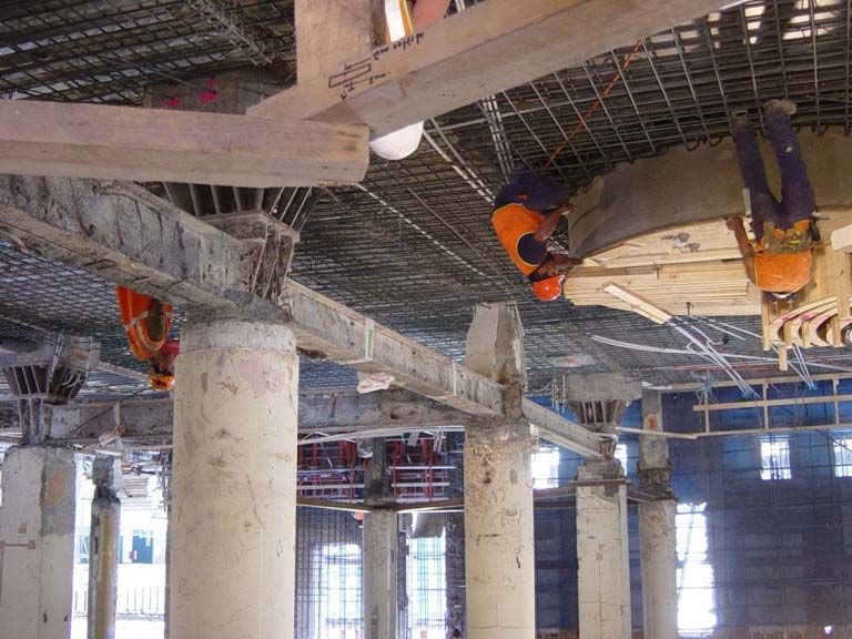
Figure 1 : Front of Building
6Figure 2 : Completed Ground Floor
Figure 3 : Steel Floor Diaphragm
Figure 4 : Lowering the Ground Floor
7Figure 5: Plan of Ground Floor
Figure 6: Longitudinal Section
8You can also read