Corrosion resistance of steel for coiled tubing units - E3S Web ...
←
→
Page content transcription
If your browser does not render page correctly, please read the page content below
E3S Web of Conferences 230 , 01018 (2021)                              https://doi.org/10.1051/e3sconf/202123001018
Gas Hydrate Technologies: Global Trends, Challenges and Horizons - 2020

          Corrosion resistance of steel for coiled tubing
          units
          Andriy Syrotyuk1*, Oleg Vytyaz 2, Rostyslav Leshchak1, and Jan Ziaja3
          1
            Karpenko Physico-Mechanical Institute of the National Academy of Sciences of Ukraine,
          Department of Strength of Materials and Structures in Hydrogen-Containing Environments,
          5 Naukova St, 79060, Lviv, Ukraine
          2
            Ivano-Frankivsk National Technical University of Oil and Gas, Institute of Petroleum Engineering,
          15 Karpatska St, 76019, Ivano-Frankivsk, Ukraine
          3
            AGH University of Science and Technology, Department of Drilling and Geoengineering,
          30 A. Mickiewicza St, 30-059, Krakow, Poland

                        Abstract. The gravimetric method was used to determine the corrosion
                        rate of a pipe for coiled tubing. Scanning electron and optical microscopy
                        were used to study the microstructure and to determine the nature of
                        corrosion damages. It has been found that corrosion processes of different
                        nature occurred in the studied systems “metal – environment”, in
                        particular, in acid solutions, corrosion was caused by the of hydrochloric
                        acid and the ambient temperature of 70°С. In solution with a smaller acid
                        content, along with the general corrosion, there is a significant localization
                        of the corrosion process (deep corrosion damage is formed: macro pitting
                        and corrosion ulcers). The general corrosion was observed in the HCl
                        solution (13 mass %), which destroys the pipe walls after 576 h of
                        exposure. The neutral solutions caused the general corrosion of smaller
                        intensity in comparison with the acidic environments, even taking into
                        account the temperature factor. The surface-active substances or petroleum
                        products that are present in the solutions, form barrier films on the steel
                        surface, which prevent the access of corrosive components from the
                        environment to the surface of the material, especially during the short
                        exposure time. With the increase of the exposure at the elevated
                        temperatures, the barrier films break down and the steel surface undergoes
                        the general corrosion.

          1 Introduction
          One of the main current trends in the global gas and oil industry is to enhance the efficiency
          of hydrocarbons production. Today, there are various ways to increase the efficiency of gas
          and oil production: the influence on reservoirs, the use of new technologies for drilling
          wells, modern equipment for overhaul and restoration of wells, etc.
              However, a special place among the above methods is occupied by “coiled tubing” (CT)
          technologies, which are based on the use of a very long metal pipe. They have high
          economic efficiency, are in a state of continuous development and improvement [1, 2], and

          *
              Corresponding author: syrotyuk@ipm.lviv.ua

    © The Authors, published by EDP Sciences. This is an open access article distributed under the terms of the Creative
    Commons Attribution License 4.0 (http://creativecommons.org/licenses/by/4.0/).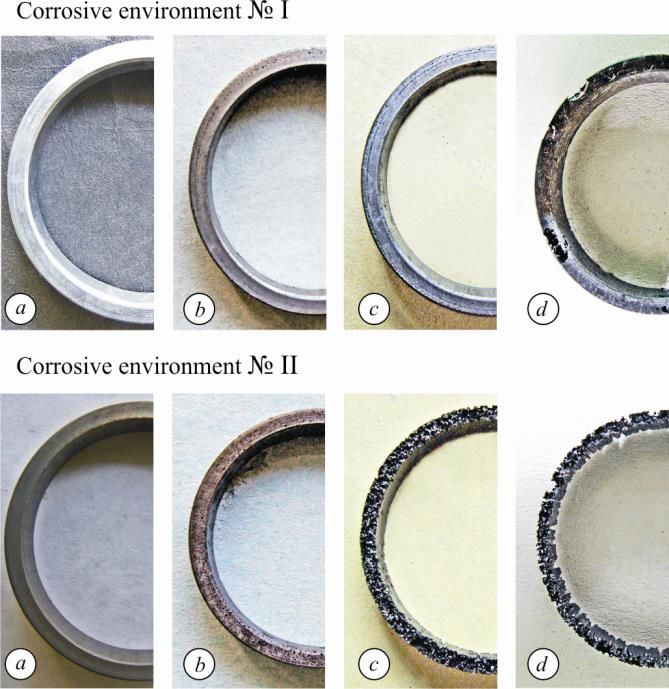
E3S Web of Conferences 230 , 01018 (2021)                              https://doi.org/10.1051/e3sconf/202123001018
Gas Hydrate Technologies: Global Trends, Challenges and Horizons - 2020

         there exists a certain international association to coordinate these efforts (Intervention &
         Coiled Tubing Association (ICoTA) https://www.icota.com/).
             The main element of the whole complex of equipment is a welded metal pipe with a
         length of 3-9 km (or more), wound on a drum. It should be noted that pipe CT works in the
         elastic-plastic area of deformation, and this causes special requirements for the quality of
         the pipe, and, consequently, to the characteristics of the pipe material and production
         technology. Nevertheless, as a result of long-term operation, local destruction of pipes is
         possible, which will cause an emergency situation [3, 4].
             CT pipes work under cyclic bending loads and combined action of aggressive working
         environments [4], which contributes to the manifestations of corrosion [5, 6]. At the same
         time, localized metal pipe corrosion is characterized by the highest velocities, especially
         under the action of cyclic and bending loads [7].
             The combined effect of fatigue and corrosion is one of the main causes of emergencies
         before the depletion of the resource of the CT pipes, caused by surface damage and at loads
         much lower than permissible [3, 4]. The decrease in the resistance to the cracks propagation
         in the material, and consequently the decrease in the resource of the CT pipes, is most
         likely due to the formation of fatigue cracks from surface defects [8, 9] (mechanical defects
         or corrosion damage) at high cross-sectional stresses.
             According to the statistic data of oil and gas companies operating in Ukraine and
         actively using CT technologies, the most common damages of pipes in their practice are:
             1. Mechanical damage:
             – damage by holding dies;
             – erroneous closing of the valve on the fountain fittings;
             – emergency lift with injector defects.
             2. Operational damage:
             – blowholes on the pipe (depressurization of the pipe by the violation of the washing
         technology);
             – buckling of the pipe caused by the excess of differential pressure;
             – pits on the pipe surface, formed by the violation of the technology of leaching of propane.
             3. CT pipes damage due to acids or gas hydrates:
             – fracture of the pipe by the violation of chemical treatment technology (Fig. 1);
             – corrosion damage during long-term storage of pipe with violation of preservation
         technology;
             – gas hydrates cause of internal pitting corrosion of CT pipes, which is observed as the
         neutral and so the acidic environments.

         Fig. 1. Corrosion damage to the CT pipe after acid jobs.

                                                           2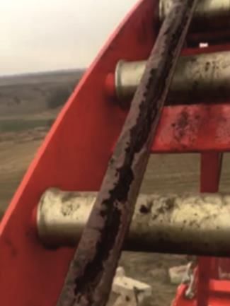
E3S Web of Conferences 230 , 01018 (2021) https://doi.org/10.1051/e3sconf/202123001018
Gas Hydrate Technologies: Global Trends, Challenges and Horizons - 2020
4. Damage caused by long operation and violation of terms for periodic control of CT
pipes state:
– fatigue damage, flaw;
– break, fractures of the CT pipes (excess of the number of tripping operations (TO)).
Given the complexity of the TO, the injection of reagents [10], and compliance with the
technology of work, attention is mainly paid to the number of TO. Cases of mechanical or
fatigue damage during winding and unwinding are investigated, and much less attention is
paid to the issue of corrosion [11-13].
2 Methods
QT-800 steel [14], from which CT pipes are made, was tested. It is high-strength low-alloy
steel [15] with alloying additives to ensure resistance to atmospheric corrosion. The nominal
chemical composition meets the requirements of the standard API 5ST CT80: 0.150 mass % C;
≤ 0.430 Si; 0.820 Mn; 0.570 Cr; ≤ 0.019 P; ≤ 0.001 S; ≤ 0.220 Cu; ≤ 0.08 Ni; 0.19 Mo; 0.017
Nb; 0.010-0.020 Ti; 0.015-0.040 V; 0.070-0.120 Al, remainder – Fe. Mo and Nb increase the
hardenability of steel and improve the conversion of ferrite. Steel structure: polygonal ferrite
and granulated bainite [16]. Microstructural features of steel are shown in Fig. 2.
Fig. 2. The structure (×1000) of QT-800 steel after etching.
Such corrosive environment were used:
– I – acid solution, recipe 1 (low content HCl + complex of additives);
– II – acid solution, recipe 2 (13 mass % HCl + complex of additives);
– III – special aqueous solution NS4 [17], modeling groundwater in neutral soils
(0.122 g/l KCl; 0.483 g/l NaHCO3; 0.137 g/l CaCl 2; 0.131 g/l MgCl 2);
– IV – formation water + SAS (surface-active substances);
– V – condensate from the Yablunivsky oil and gas condensate field.
Corrosion investigations. Samples for tests for general corrosion [18-20] were cut from
a CT pipe 38.1×2.77 mm by a technology, which made it possible to consider the
peculiarities of CT production. They had the same shape and size, they were ground (to
roughness Ra = 0.63 m), degreased with acetone, dried, and kept in a desiccator for 2 h.
The samples were completely immersed in a corrosive medium and kept in a thermostat
at a temperature of 70°C to reproduce real operating conditions [21, 22].
The corrosion rate Km was determined by the gravimetric method after exposure to a
corrosive environment under natural aeration and removal of corrosion products. Weighed
on the analytical weighing stales with an error of ±0.0001 g. To calculate the corrosion rate
the known formula was used:
3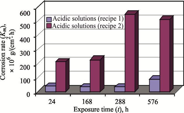
E3S Web of Conferences 230 , 01018 (2021) https://doi.org/10.1051/e3sconf/202123001018
Gas Hydrate Technologies: Global Trends, Challenges and Horizons - 2020
m , g/(cm2·h), (1)
Km
S t
where Δm – the change in mass of the sample after exposure to a corrosive environment and
the removal of corrosion products (g); S – the surface area of the sample (cm2); t – duration of
exposure (h). EVO-40XUP (Zeiss) scanning electron microscope was used to determine the
nature of corrosion damage.
3. Results and discussion
According to the results of studies of total corrosion in five working solutions, it was found
that the corrosion rate in acidic [22, 23] solutions (I, II) is significantly higher than in
neutral [24] (III, IV, and V). For ease of analysis, the results of corrosion studies are
presented separately for acidic and neutral working solutions.
The highest corrosion rate (Fig. 3) was observed in solution II consisting of 13 mass %
HCl, this is the most aggressive solution among the studied. Here, an increase in the
corrosion rate was observed in time up to 288 h of exposure, after which the corrosion rate
decreased slightly. This extreme nature of the change in the corrosion rate is due to several
factors. The corrosion process is a surface phenomenon, in which the metal surface
dissolves. Since the primary surface area is taken into account when calculating the
corrosion rate, then under an extremely active working environment (13 mass % HCl and
70°С) the active surface area will increase due to the increase of surface relief (Fig. 4)
during exposure to aggressive environments. (Fig. 3).
Fig. 3. The corrosion rate of QT-800 steel vs different times of exposure in an acid corrosive environment.
After 288 h of exposure, the corrosion rate slightly decreases due to the solution
depletion (reduction of the proportion of free corrosive components of the solution) and
reduction of the active surface area due to metal dissolution in an aggressive working
environment, what is confirmed by significant weight loss of the studied sample (Figs. 3
and 4). The steel corrosion rate in the solution I much lower compared to solution II, due to
the lower aggressiveness of this working environment under operating conditions. However,
the corrosion process is more active in comparison with neutral working media, and shows a
steady increase in rate during exposure from 24 to 576 h, due to, as in the previous case, the
increase in the active surface area of the sample during the experiment. Here, as in the
previous case, the process of general corrosion is observed which is reflected in a significant
loss of material over time, and a significant localization of the corrosion process (deep
corrosion damage to the surface of samples such as micro pitting and corrosion pits).
4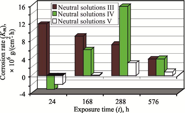
E3S Web of Conferences 230 , 01018 (2021)                              https://doi.org/10.1051/e3sconf/202123001018
Gas Hydrate Technologies: Global Trends, Challenges and Horizons - 2020

         Fig. 4. The surface of the samples after exposure to acidic solutions recipe 1 and recipe 2 duration
         24 h (a), 168 h (b), 288 h (c), and 576 h (d).

             However, in this case, the process of local corrosion is more pronounced compared to the
         previous one, which is due to less activity of the working environment, and consequently less
         intensity of the general corrosion process.
             A classical process of corrosion rate decrease during exposure in solution III was
         observed (Fig. 5) due to the reduction of the active surface over time because of the passive
         oxide and hydroxide film formation on the metal surface. Here, the corrosion rate is higher
         as compared to standard experimental conditions, resulting from the high ambient
         temperature (70°C).

         Fig. 5. The corrosion rate of QT-800 steel vs different times of exposure in the neutral corrosive environment.

            The presence of SAS in environment IV influences the steel corrosion (Fig. 5) in the
         working environment. During the first 24 hours, barrier films are formed on the steel surface,
         which is reflected in the conditionally negative corrosion rate. The corrosion rate was

                                                                5
E3S Web of Conferences 230 , 01018 (2021) https://doi.org/10.1051/e3sconf/202123001018
Gas Hydrate Technologies: Global Trends, Challenges and Horizons - 2020
determined by the gravimetric method, so the mass of the samples after exposure to 24 h in
the working environment is greater than the initial one, due to the deposition of SAS on the
material surface and the formation of a barrier film. It makes it difficult for corrosive active
components of the environment to access the surface of the material. As exposure to high
temperatures increases, the barrier films gradually break down. After exposure for 288 h, the
corrosion rate is higher even than NS4 (environment III) after 24 h (Fig. 6).
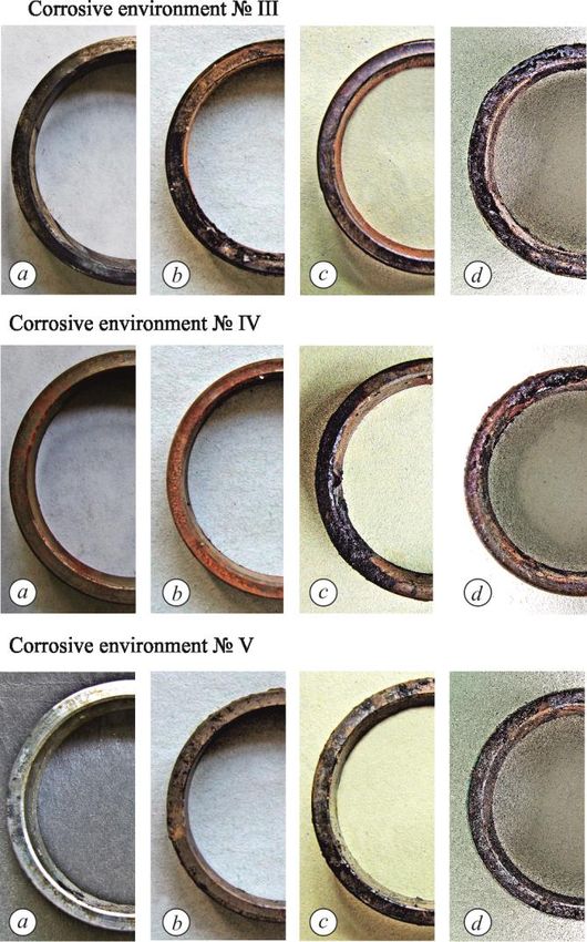
Fig. 6. The surface of the samples after exposure in the neutral solutions (ІІІ, ІV, V) duration 24 h (a),
168 h (b), 288 h (c), and 576 h (d).
This is due to the higher corrosion activity of the medium compared to NS4, and a fairly
significant porosity of the formed barrier film at a temperature of 70°C, which accelerates
corrosion processes. After exposure to 576 h, the corrosion rates of the test material in
media III and IV, in NS4 and in formation water, respectively, are practically equalized,
which is explained by the loss of barrier properties of the formed film.
Corrosion processes in the condensate from the Yablunivsky oil and gas condensate
field (solution V) have similar tendencies to change the rate of the corrosion process as in
6E3S Web of Conferences 230 , 01018 (2021) https://doi.org/10.1051/e3sconf/202123001018
Gas Hydrate Technologies: Global Trends, Challenges and Horizons - 2020
solution IV. Presumably, such nature of the corrosion rate changes is stipulated by the same
reasons as in the previous case, but this medium is less corrosive, which causes the decrease
of the corrosion rate indicators in 4-6 times.
4. Conclusions
It has been found that corrosion processes of different nature occurred in the studied
systems “metal – environment”, In particular, in acid solutions, corrosion was caused by the
content? of hydrochloric acid and the ambient temperature of 70°С. In solution with a
smaller acid content, along with the general corrosion, there is a significant localization of
the corrosion process (deep corrosion damage is formed: macro pitting and corrosion
ulcers). The general corrosion was observed in the HCl solution (13 mass %), which
destroys the pipe walls after 576 h of exposure.
The neutral solutions caused the general corrosion of smaller intensity in comparison
with the acidic environments, even taking into account the temperature factor. The surface-
active substances or petroleum products that are present in the solutions, form barrier films
on the steel surface, which prevent the access of corrosive components from the
environment to the surface of the material, especially during the short exposure time. With
the increase of the exposure at the elevated temperatures, the barrier films break down and
the steel surface undergoes the general corrosion.
In practice, after finishing work with acid solutions, it is necessary to neutralize their
action with alkalis, since the residues of acid solutions or their vapors can accumulate in the
coils of CT pipes and favor the development of local corrosion damages.
Continuing to work in this direction, the authors want to consider in more detail the
action of gas hydrates on the corrosion resistance [18, 19, 24] of CT pipes. Especially,
action acidic gases such as H2S and CO2, which are components of gas hydrates, and
dissolve in water, can accelerate the internal pitting corrosion of CT pipes.
The presented study was conducted within the project R6.1 “Development of new methods for
improving reliability and durability of the flexible pipes for gas and oil extraction by the coiled tubing
technologies” of the Targeted Programme of Scientific Research of National Academy of Sciences of
Ukraine “Reliability and durability of materials, constructions, equipment and structures” (“RESURS-2”).
References
1. Padron, T., & Craig, S.H. (2018). Past and present coiled tubing string failures – history and
recent new failures mechanisms. Society of Petroleum Engineers – SPE/ICoTA Coiled Tubing and
Well Intervention Conference and Exhibition 2018. https://doi.org/10.2118/189914-MS
2. Myatt, J., Lynn, S., Craig, S., Murphy, S., Correa, P., & Padron, T. (2015). Challenging
conventional fluid practices for coiled tubing drilling. Society of Petroleum Engineers – Coiled
Tubing and Well Intervention Conference and Exhibition 2015, 317-330.
https://doi.org/10.2118/173661-MS
3. Zhou, Z., Tan, J., Wan, F., & Peng, B. (2019). Improvement and determination of the influencing
factors of coiled tubing fatigue life prediction. Advances in Mechanical Engineering, 11(9),
168781401988013. https://doi.org/10.1177/1687814019880131
4. Sherman, S., Majko, S. M., & Otto, J. (2020). High strength coiled tubing – how is fatigue life
affected by slip damage? Society of Petroleum Engineers – SPE/ICoTA Well Intervention
Conference and Exhibition 2020. https://doi.org/10.2118/199859-MS
5. Wei, X, Dong, J., Chen, N., Yadav, A.P., Ren, Q., Wei, J., & Ke, W. (2021). Effects of bentonite
content on the corrosion evolution of low carbon steel in simulated geological disposal environment.
Journal of Materials Science & Technology, (66), 46-56. https://doi.org/10.1016/j.jmst.2020.04.071
7E3S Web of Conferences 230 , 01018 (2021) https://doi.org/10.1051/e3sconf/202123001018
Gas Hydrate Technologies: Global Trends, Challenges and Horizons - 2020
6. Zhao, W., Xiao, J., Saiood, H.A., Otaibi, A.B., Huang, J., & Chang, F.F. (2020). Chemical
solution to ESP packer penetrator corrosion problem. International Petroleum Technology
Conference. https://doi.org/10.2523/iptc-19633-abstract
7. Li, L., Shen, Z.X., & Wang, P. (2013). Research the coiled tubing deformation under internal
pressure and cyclic bending. Applied Mechanics and Materials, (421), 62-65.
https://doi.org/10.4028/www.scientific.net/amm.421.62
8. Akid, R., Dmytrakh, I.M., & Gonzalez-Sanchez, J. (2006). Fatigue damage accumulation: The
role of corrosion on the early stages of crack development. Corrosion Engineering Science and
Technology, 41(4), 328-335. https://doi.org/10.1179/174327806X139108
9. Syrotyuk, А.M., & Dmytrakh, I.M. (2014). Methods for the evaluation of fracture and strength of
pipeline steels and structures under the action of working media. Part І. influence of the corrosion
factor. Materials Science, 50(3), 324-339. https://doi.org/10.1007/s11003-014-9724-5
10. Ziaja, J., Stryczek, S., & Jamrozik, A. (2017). Sealing slurries limiting natural gas exhalations
from the annular space of a wellbore [Zaczyny uszczelniajaące ograniczajaące eltshalacje gazu
ziemnego z przestrzeni pierścieniowej otworu wiertniczego]. Przemysl Chemiczny, 96(5), 990-992.
https://doi.org/10.15199/62.2017.5.9
11. Syrotyuk, А., Vytyaz, О., & Ziaja, J. (2017). Damage to flexible pipes of coiled tubing equipment
due to corrosion and fatigue: methods and approaches for evaluation. Mining of Mineral Deposits,
11(4), 96-103. https://doi.org/10.15407/mining11.04.096
12. Duque, L.H., Guimarães, Z., Berry, S.L., & Gouveia, M. (2008). Coiled tubing and nitrogen
generation unit operations: Corrosion challenges and solutions found in brazil offshore
operations. Society of Petroleum Engineers – Coiled Tubing and Well Intervention Conference
and Exhibition 2008, 240-254. https://doi.org/10.2118/113719-MS
13. Ziaja, J., Jamrozik, A., & Wiśniowski, R. (2019). Modified drilling fluids for workover jobs in oil
wells. International Multidisciplinary Scientific GeoConference Surveying Geology and Mining
Ecology Management, 19(1-2), 1017-1024. https://doi.org/10.5593/sgem2019/1.2/S06.129
14. Hagianu, A., Nae, I., Ionescu, G.C., & Ripeanu, R. G. (2020). Research on mechanical and
geometrical characteristics of materials used for flexible tubing production. IOP Conference
Series: Materials Science and Engineering, (724), 012004. https://doi.org/10.1088/1757-
899X/724/1/012004
15. Ghiasi, H. (2018). Evaluation of microstructural effects on mechanical properties of CT80 grade
coiled tubing steel. Scientia Iranica, 25(4), 2155-2161. https://doi.org/10.24200/sci.2018.20677
16. Zhou, L., Jiang, B., Li, M., Yuan, F., Zhang, C., & Liu, Y. (2014). Microstructure control of non-
quenched and tempered ct80 grade coiled tubing steel. Acta Metallurgica Sinica (English Letters),
27(3), 464-468. https://doi.org/10.1007/s40195-014-0063-1
17. Dmytrakh, I.M., Smiyan, O.D., & Syrotyuk, A.M. (2010). Experimental study of fatigue crack
growth in pipeline steel under hydrogenating conditions. 18th European Conference on Fracture:
Fracture of Materials and Structures from Micro to Macro Scale.
18. Poberezhny, L., Hrysanchuk, A., & Grytsuliak, H. (2019). Influence of the gas hydrates on the
corrosion rate of gas gathering pipelines. Procedia Structural Integrity, (16), 141-147.
https://doi.org/10.1016/j.prostr.2019.07.033
19. Hua, Y., Barker, R., & Neville, A. (2014). Effect of temperature on the critical water content for
general and localised corrosion of X65 carbon steel in the transport of supercritical CO2.
International Journal of Greenhouse Gas Control, (31), 48-60.
https://doi.org/10.1016/j.ijggc.2014.09.026
20. Abdulridha, A.A., Allah, M.A.A.H., Makki S.Q. et al. (2020) Corrosion inhibition of carbon steel
in 1 M H2SO4 using new Azo Schiff compound: Electrochemical, gravimetric, adsorption,
surface and DFT studies. Journal of Molecular Liquids, 315, 113690,
https://doi.org/10.1016/j.ijggc.2014.09.026
21. Krueger, S., & Schoenborn, K. (2020). New high temperature coiled tubing drilling bottom hole
assembly enables slimhole re-entry drilling in challenging high temperature wells. Society of
Petroleum Engineers – SPE/ICoTA Well Intervention Conference and Exhibition 2020.
https://doi.org/10.2118/199842-MS
8E3S Web of Conferences 230 , 01018 (2021) https://doi.org/10.1051/e3sconf/202123001018
Gas Hydrate Technologies: Global Trends, Challenges and Horizons - 2020
22. Saeed, A., Hamid, S., Yakovlev, T., Sagr, H., & Harthi, S. (2020). Worldwide first successful
production logging of tri-lateral high temperature coiled tubing drilled sour gas well, performed in
a single run using innovative reentrance system without whipstock guides. Society of Petroleum
Engineers – SPE/ICoTA Well Intervention Conference and Exhibition 2020.
https://doi.org/10.2118/199872-MS
23. Al-Nakhli, A., Arifin, M., & Ahmed, D. (2019). Novel application of distributed temperature
sensing and CT real-time downhole flow measurement tool for thermochemical treatments.
International Petroleum Technology Conference 2019. https://doi.org/10.2523/19307-MS
24. Newman, K., Kelleher, P., & Gunby, B. (2017). Optimizing CT material properties for extended
reach operations. Society of Petroleum Engineers – SPE/ICoTA Coiled Tubing and Well
Intervention Conference and Exhibition 2017. https://doi.org/10.2118/184749-MS
9You can also read