Broadband orbital angular momentum manipulation using liquid crystal thin-films
←
→
Page content transcription
If your browser does not render page correctly, please read the page content below
Broadband orbital angular momentum manipulation using
                   liquid crystal thin-films
                                Yanming Li, Jihwan Kim and Michael J. Escuti
  Dept. Electrical and Computer Engineering, North Carolina University, Raleigh, NC USA

                                                                 ABSTRACT
We introduce two high efficiency thin-film optical elements, operating over a wide spectral range, to generate and
control the Orbital Angular Momentum (OAM) of various light sources: a broadband q-plate and a broadband
Forked Polarization Grating (FPG). The broadband OAM manipulation is achieved by thin liquid crystal polymer
layers that are aligned to provide the required spatially varying anisotropy. These elements operate using
geometric phase principles to generate raised and lowered OAM modes whose efficiencies are sensitive to the
polarization state of the incident light. We discuss the design principles involved and experimentally demonstrate
broadband q-plates and FPGs that are highly efficient (> 90%) in the visible wavelength range. These thin film
elements enable easy integration into various optical systems requiring broadband OAM manipulation such as
optical trapping and high capacity information.
Keywords: orbital angular momentum, polarization gratings, liquid crystal, complex beam, broadband

                                                        1. INTRODUCTION
The momentum of a propagating light wave has both linear and angular contributions. The linear momentum is
associated with the wave vector. The angular momentum can be further broken down into two more parts: Spin
Angular Momentum (SAM) that is associated with polarization, and Orbital Angular Momentum (OAM) that
is associated with spatial distribution of the phase front. Unlike the first two, current study on OAM of light is
fairly recent. Allen et al.1 identified that lightwaves with azimuthal angle-dependent phase term exp(ilφ) carry
OAM of l per photon, where l can take any positive or negative integer. OAM is a new degree of freedom of
light that we can utilize. Moreover, comparing to SAM which can only be ± per photon, OAM could offer larger
momentum to exchange when interact with matter, or wider state set when encode information. An increasingly
intense set of work has recently been conducted on the applications of light OAM, including optical trapping2
and information science and technology.3, 4 While several OAM manipulation methods (described in more detail
below) have been suggested for these applications, none of them has the capability to function over a wide
spectral band with good power efficiency and flexibility. Highly efficient broadband OAM will be particularly
useful for applications such as OAM-based wavelength-division multiplexing.
    Current methods to generate, manipulate, and detect OAM states include the use of spiral phase plate,5
cylindrical lens pair,1 computer generated hologram (CGH), and spatial light modulator (SLM).6, 7 In general,
these conventional approaches result in bulky and expensive devices limiting the optical performance. In addition
approaches using CGHs usually result in low power efficiency while SLMs suffer from resolution and wavelength
limits. Most recently, two novel liquid crystal elements were introduced to manipulate the OAM of light. The
first is an axially varying half-wave plate called q-plate,8 where q is the singularity charge. A q-plate converts
incoming circularly polarized light to OAM l = ±2q states, and generally arbitrary polarization to a superposition
of these two OAM states. Both static and tunable versions of q-plate have been reported.9
   The second element, introduced by our group10, 11 , is a Forked Polarization Grating (FPG), which converts
incoming light with OAM l0 to one or both of the OAM l = l0 ± lg eigenstates, where lg is the singularity
charge of the FPG. As a diffractive optical element, an FPG also changes the linear momentum. Light that
goes through different OAM changes (raising or lowering, depending on input polarization), will be diffracted to
different direction as well. We recently introduced this approach with both static and switchable FPG elements
   Correspondence should be addressed to mjescuti@ncsu.edu, +1 919 513 7363

               Complex Light and Optical Forces VI, edited by Enrique J. Galvez, David L. Andrews, Jesper Glückstad,
      Marat S. Soskin, Proc. of SPIE Vol. 8274, 827415 · © 2012 SPIE · CCC code: 0277-786X/12/$18 · doi: 10.1117/12.913757

                                                        Proc. of SPIE Vol. 8274 827415-1

                        Downloaded from SPIE Digital Library on 15 Feb 2012 to 152.14.240.169. Terms of Use: http://spiedl.org/terms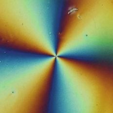
formed in liquid crystals, where high OAM conversion efficiencies of 96% were demonstrated for UV and visible
light sources.
   Both q-plates and FPGs can be tailored for nearly any wavelength from ultraviolet to infrared using com-
mercially available nematic LCs. However due to the dispersion in the LC birefringence, the high diffraction
efficiency occurs only over a modest bandwidth centered around a single optimized wavelength. Here we report
on broadband FPGs and q-plates that accomplish highly efficient (> 97%) OAM manipulation over a much wider
spectral range in the visible region (500—700 nm).

                                                           2. BACKGROUND
2.1 Polarization Gratings (PG)
PGs are a category of diffraction gratings that are formed in anisotropic materials, and function by affecting the
polarization state of the wavefront passing through them via the Pancharatnam-Berry phase effect.12–14 This
in-plane wavefront shaping occurs within a thin anisotropic layer and leads to unique behavior: 100% diffraction
into a single order for wide angular acceptance and wide range of periods. In one sub-class, researchers suggested
to embody the birefringence profile by spatially aligning liquid crystal (LC) materials,15 which was achieved with
100% efficiency by others.16–19 These PGs are thin and lightweight, operate with extremely high efficiency, and
can be made either static or switchable, narrowband or broadband.20 These attractive properties of PGs have
been used in several applications including laser beam steering,21, 22 optical filters,23, 24 polarization imaging,25, 26
and displays.27, 28 Traditional PG has a one-dimensionally spatial varying optical axis that follows Φ(x) = πx/Λ;
FPG and q-plate are two-dimensional variations of PG with Φ(x, y), of which the non-zero curl leads to OAM
change.
    A narrowband PG is tuned for half-wave retardation at a specific wavelength λ0 . The diffraction efficiency
is defined as the ratio of the output to input intensity in a particular diffraction order (m = 0, or ±1). The
zero-order is insensitive to input polarization, while the first-orders are highly polarization sensitive:16

                                                             η0 = cos2 (ζ)                                                            (1a)
                                                                  1
                                                            η±1 = (1 ∓ S3 ) sin2 (ζ)                                                 (1b)
                                                                  2
where ζ = πΔnd/λ is a normalized retardation, S3 = S3 /S0 is the normalized Stokes parameter corresponding
to the ellipticity of the incident light. When at a half-wave retardation condition (Δnd = λ0 /2), the zero-order
diffraction is suppressed, and 100% of the input is diffracted into one or both of the first-orders (depending on
polarization).

2.2 Forked Polarization Gratings (FPG)
Unlike conventional one-dimensional PGs, an FPG has a two-dimensional spatially-varying optical axis given by:
                                                                  1
                                                  Φ(x, y) =         lg φ(x, y) + φ0 − πx/Λ                                             (2)
                                                                  2
in xy plane and homogeneous
                               in the third (z) dimension. In the equation, φ(x, y) is the azimuthal angle
φ(x, y) = tan−1 xy , φ0 is some constant initial angle, lg denotes the order of the FPG, which is also called
topological charge. Λ is the grating period, which is associated with a grating vector kg (Λ) altering the beam
propagation direction. We use a ket notation for a single photon state | kg , s, l, where k stands for linear
momentum, s and l are spin and orbital angular momentum in unit of , respectively. The function of FPG can
be summarized as a operator

                                                                  1                       1
                                 F P G(k(Λ),      lg )   | kg , − , l =| k + kg (Λ), + , l − lg                                 (3a)
                                                                   2                       2
                                                                  1                       1
                                 F P G(k(Λ),      lg )   | kg , + , l =| k − kg (Λ), − , l + lg                                 (3b)
                                                                   2                       2

                                                          Proc. of SPIE Vol. 8274 827415-2

                       Downloaded from SPIE Digital Library on 15 Feb 2012 to 152.14.240.169. Terms of Use: http://spiedl.org/terms
(a)
y
0 Λ 2Λ
x
(b)
d
photo-
d alignment
z layers
glass ITO
x
Figure 1. Broadband PG. Local optical axis profile (a) top view and (b) side view.
For coherent light field of arbitrary polarization which is essentially the superposition of | + 12 and | − 12 , FPG
acts as a linear operator and the output is the superposition of the two result states in Eq. 3. In other words,
m = 1(m = −1) diffraction order comes from the left(right) circularly polarized contribution of the incoming
lightwave, it is converted to the opposite circular polarization, with OAM charge decreased(increased) by lg .
2.3 q-plate
A q-plate functions like an FPG, except it does not affect linear momentum. Essentially it is an extreme case of
FPG that has an infinite grating period Λ. Its optical axis follows
Φ(x, y) = qφ(x, y) + φ0 (4)
where q is the topological charge of a q-plate. Its function can be summarized
l | − 1 , l =| + 1 , l − lg
QP (5a)
g
2 2
1 1
l | + , l =| − , l + lg
QP g
(5b)
2 2
Thus, q-plate and FPG are alike in the sense of OAM control. Eq. 1 applies to both as η0 is the efficiency of
unchanged field and η±1 are of the two possible modulated OAM beams, respectively. We notice that q-plates
work on-axis and FPGs work off-axis. This makes each superior for various applications. A q-plate is easy to
align optically, however, for arbitrary polarized input its output is not a pure helical mode. On the other hand,
an FPG always alter the beam direction by producing the different OAM states as individual diffracted orders,
but each of these orders always produce pure helical beams form helical input regardless of the polarization.
2.4 Broadband PG
Introduced by Oh et al.,14, 20 a broadband one-dimensional PG comprises two antisymmetric chiral circular PGs
with an opposite twist sense, where the local optical axis follows
Φ(x, 0) + Φ0 z/d if 0 ≤ z ≤ d
Φ(x, z) = (6)
Φ(x, 0) − Φ0 z/d + 2Φ0 if d ≤ z ≤ 2d
where d is the thickness, and Φ0 is the twist angle of each chiral layer. Fig. 1 illustrates this profile. With
the two antisymmetric chiral layers counteracting chromatic dispersions in the linear and twist-induced circular
birefringences, this double twist structure creates a self-compensation that leads to a half-wave retardation
condition over a wide bandwidth. This then leads to new efficiency equations:20
η0 (λ) = 1 − K (7a)
1
η±1 (λ) = (1 ∓ S3 )K (7b)
2
Proc. of SPIE Vol. 8274 827415-3
Downloaded from SPIE Digital Library on 15 Feb 2012 to 152.14.240.169. Terms of Use: http://spiedl.org/termsacross a fairly wide bandwidth, where K is a parameter determined by the LC structure and it is approximately
1 within this range. A bandwidth
Δλ/λ0 can be defined as the ratio of the spectral range Δλ (over which
high diffraction efficiency η±1 ≥ 99% occurs) to the center wavelength λ0 . Through a series of optimizations,
this bandwidth is maximum when when Φ0 = 70◦ . This represents a fourfold enhancement as compared to a
narrowband PG discussed earlier.
3. BROADBAND FPG AND BROADBAND Q-PLATE
We can extend the broadband PG design principles discussed to create broadband FPGs and q-plates. Notice that
the explicit expression of the surface optical axis pattern Φ was not part of the derivation and does not appear
in the efficiency equations Eq. 7. In other words, although the broadband theory was originally developed for
conventional one-dimensional PGs (Φ(x)), we can expand it to two-dimensional PGs (Φ(x, y)) as well. Therefor,
we introduce the broadband variation of FPG and q-plate that is based on this double twist structure
Φ(x, y, 0) + Φ0 z/d if 0 ≤ z ≤ d
Φ(x, y, z) = (8)
Φ(x, y, 0) − Φ0 z/d + 2Φ0 if d ≤ z ≤ 2d
where the surface local optical axis Φ(x, y, 0) follows Eq. 2 and Eq. 4 for FPG and q-plate, respectively. These
broadband FPGs and broadband q-plates should have both the OAM manipulation capabilities and the high
diffraction efficiencies over a wide range of wavelength.
4. FABRICATION
We have experimentally realized broadband FPGs and q-plates formed as liquid crystal thin films fabricated
by polarization holography and photoalignment techniques. We utilized a linear photopolymerizable polymer
(LPP) as the photoalignment material (ROP108, Rolic Ltd). The surface alignment pattern was recorded in the
LPP layer using an HeCd laser (325 nm). For q-plates, this pattern was created by a rotating line beam with
appropriately controlled linear polarization.10, 29 For FPGs, we utilize polarization holography with a q-plate as
helical beam generator. After UV exposure, liquid crystal polymer (LCP) was spin-coated onto the patterned
LPP-coated substrate. We utilized RMS03-001C (EMD Chemicals, Δn0.16 @ 589 nm) to create this birefringent
LCP film, according to the method previously reported.20 A diluted mixture (1:3 of RMS03-001C:PGMEA) layer
was first coated to improve later coating quality. The next layer, the first chiral layer, was composed of the LCP
doped with a small amount (approximately 0.3%) of the chiral molecule CB15 (EMD Chemicals). The last layer,
the second chiral layer, was composed of the LCP doped with a small amount (approximately 0.3%) of the chiral
molecule MLC-6742 (EMD Chemicals). The thickness of layers were tuned so that the half-wave retardation
Δnd = λ0 /2 (at λ0 = 550 nm) and a twist Φ = +70◦ occurred simultaneously. Spin-coating speeds were 2000
rpm for the diluted LC layer, 580 rpm and 530 rpm for the first and second chiral layers, respectively.
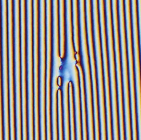
Polarizing microscope pictures of the samples are shown in Fig. 2 that indicate good LC alignment producing
the required spatial pattern in both cases. Both elements are made on one inch square substrates. The FPG
has a period of 10 μm, picture is zoomed in to show the fork-shaped singularity. These results are comparable
to prior work on such elements. Next, we attempt to further characterize the optical properties of both the
broadband FPG and q-plate.
5. EXPERIMENTAL RESULTS
5.1 Polarization-controlled OAM conversion
The characterization of the OAM conversion is conducted with a Mach-Zender interferometer. With Gaussian
mode laser beam (l = l0 ) incident, the output beams are examined by interfering with a tilted plan wave. To
demonstrate broadband ability, we repeated this examination using two lasers at 633 nm and 532 nm, respectively.
Captured interference patterns are shown in Fig. 3 with optical path illustrations with them.
The result perfectly agrees with the theory. Predicted patterns are observed at both wavelengths. For FPGs,
both circularly and linearly polarized input were tested. Circular input will diffract to a single first order and
Proc. of SPIE Vol. 8274 827415-4
Downloaded from SPIE Digital Library on 15 Feb 2012 to 152.14.240.169. Terms of Use: http://spiedl.org/terms20 µm 5 mm
(a) FPG, lg = 1 (b) q-plate, q = 1
Figure 2. Polarizing microscope pictures of (a) a broadband FPG (zoomed in at singularity) and (b) a broadband q-plate.
linear input will diffract to both first orders. At the same time, all polarizations have a very weak zero order
leakage. As shown in Fig. 3(a), the zero order diffraction is always unchanged, with l = l0 = 0, and the first
orders are always modulated: OAM of m = −1 diffraction is increased by lg = 1, which in this case, equals to
1, and for m = +1 diffraction, OAM is decreased by lg = 1, to l = −1. For q-plates, circular polarized input
is also converted to helical beam (Fig. 3(b)). Opposite polarization handedness result in the same OAM value
but opposite helical handedness. Linear polarized input is converted to a superposition of helical modes, which
is essentially an “axial polarized beam”. This spatial varying linear polarization can be examined by observing
its intensity distribution through an analyzer (Fig. 3(c)).
5.2 Conversion efficiency
To measure the conversion efficiency over the visible range we took the transmission spectra with an unpolarized
broadband light source. Due to the diffractive feature of a broadband FPG, its useful output (first orders) can be
easily selected by a spatial filter. We measured the zero order transmission by a spectrometer and normalized it
by the reference total transmission of a bare glass substrate to get normalized zero order diffraction efficiency η0 .
This normalization excludes the effect of substrate reflection and absorption, which could be prominently
reduced
by proper coating. Then we estimated the normalized total first order diffraction efficiency η± = 100% − η0 ,
shown in Fig. 4. We did this estimation because zero order is non-dispersive thus can be measured most accurately.
Clearly, the broadband FPG manifests high diffraction efficiency 97% across almost all visible wavelengths (483—
720 nm) , which is a substantial improvement over the narrowband FPG (580—675 nm), almost 2.5 times wider.
A spectrum of a sample optimized for 633 nm is shown in the figure as reference. Direct first order efficiency
measurements using lasers are also shown here as markers. Diffraction efficiency is calculated by single order
intensity over total transmitted intensity. A 2% difference from estimated values is due to high order diffraction,
scattering ,and some material absorption. This should be further optimized by improving fabrication details as
we will discuss in a later section. q-plates fabricated using the same recipe should have the same theoretical
efficiency as FPGs. However, because output from q-plates is not spatially separated, we used a different approach
to measure the efficiency by filtering out the useful fraction by polarization. With circularly polarized input,
the modulated fraction reverts its handedness, whereas the unmodulated leakage fraction remains the same.
Thus, by measuring the transmission through circular polarizer, we verified the q-plates conversion efficiency of
> 97.6% at both 532 nm and 633 nm by lasers.
6. DISCUSSION
We fabricated broadband FPGs and broadband q-plates that extent the working bandwidth significantly compar-
ing to their narrowband versions. These elements have two main advantages over others. First, they can be used
to control OAM of a broadband light with high efficiency, which could not be achieved by narrowband elements.
For example, a narrowband FPG will have significant higher zero-order leakage at off-center wavelengths, making
it low efficient for overall bandwidth. A narrowband q-plate has even more trouble with broadband light, since
the zero-order leakage will superimpose with first-orders and make the output a complex OAM state that varies
across the spectral band. The essential that makes our new thin films broadband is the material. Because of
Proc. of SPIE Vol. 8274 827415-5
Downloaded from SPIE Digital Library on 15 Feb 2012 to 152.14.240.169. Terms of Use: http://spiedl.org/terms(a) (b) (c)
m = -1 m=0 m = +1
FPG q-plate
Figure 3. Pictures of output from (a) FPG (lg = 1) and (b-c) q-plate (q = 1). Top: HeNe (633 nm) red laser; bottom:
NdYAG (532 nm) green laser. First row: far field intensity. Second row: (a-b) interference with tilted plane wave or (c)
intensity through an analyzer.
the two opposite chiral doping, there are more parameters we could adjust in the LC coating process in order
to adjust both the shape and the position of the spectrum. Although our current recipe is optimized to cover
the visible range, these elements are capable of serving other spectral ranges as well. This feature makes the
simultaneous OAM controlling of a broadband light field easily achievable and could be particularly useful in
wavelength-division multiplexing in OAM-based systems.
Second, these elements are easy to fabricate. Because the broadband versions have the same surface alignment
patterns as conventional narrowband versions, they can be easily fabricated by photo-alignment techniques that
are currently available. Generally, for most arbitrary two-dimensional LC element, we can keep its surface
alignment and introduce this double twist structure to make it broadband. As a result, many nice features of
narrowband FPGs and q-plates still apply to our broadband elements. For instance, they have good diffraction
efficiency, polarization-controlled conversion, they are light weight and flexible. Combining with their wide
working wavelength range, this elements are extremely unique and excellent OAM controllers.
Proc. of SPIE Vol. 8274 827415-6
Downloaded from SPIE Digital Library on 15 Feb 2012 to 152.14.240.169. Terms of Use: http://spiedl.org/terms100
Diffraction Efficiency [%]
80 Broadband
60 95.2% 95.0%
(532 nm) (633 nm)
40
20
(Narrowband)
0
400 500 600 700 800
Wavelength [nm]
Figure 4. Broadband FPG first order efficiency spectrum from spectrometer (curves) and laser (markers) measurements.
The spectrum of a narrowband FPG optimized for 633 nm is shown for comparison.
7. CONCLUSION
We introduced two broadband OAM mode generator and transformers using LC thin films. We demonstrated
that with our polarization holography and photo-alignment technique we can make high-quality broadband FPGs
and broadband q-plates. Their OAM controlling functions are verified with high conversion efficiency (> 97%) in
a wide range of visible spectrum (480—720 nm). These elements are thin and light weight, easily processed, and
quick responding. They show an efficient mechanical-free method to control OAM of a broadband light source,
which will benefit many applications including ultra high capacity information technology.
8. ACKNOWLEDGMENT
The authors gratefully acknowledge the support of the National Science Foundation (CAREER award ECCS-
0955127).
REFERENCES
[1] Allen, L., Beijersbergen, M., Spreeuw, R., and Woerdman, J., “Orbital angular momentum of light and the
transformation of Laguerre-Gaussian laser modes,” Phys. Rev. A 45(11), 8185–8189 (1992).
[2] Garcés-Chávez, V., McGloin, D., Padgett, M., Dultz, W., Schmitzer, H., and Dholakia, K., “Observation of
the Transfer of the Local Angular Momentum Density of a Multiringed Light Beam to an Optically Trapped
Particle,” Phys. Rev. Lett. 91(9), 093602 (2003).
[3] Knill, E., Laflamme, R., and Milburn, G. J., “A scheme for efficient quantum computation with linear
optics,” Nature 409(6816), 46–52 (2001).
[4] Gibson, G., Courtial, J., Padgett, M., Vasnetsov, M., Pas’ko, V., Barnett, S., and Franke-Arnold, S.,
“Free-space information transfer using light beams carrying orbital angular momentum,” Opt. Lett. 12(22),
5448–5456 (2004).
[5] Beijersbergen, M., “Helical-wavefront laser beams produced with a spiral phaseplate,” Opt. Commun. 112(5-
6), 321–327 (1994).
[6] Bazhenov, V., Soskin, M. S., and Vasnetsov, M. V., “Screw Dislocations in Light Wavefronts,” J. Mod.
Optic. 39(5), 985–990 (1992).
[7] Jack, B., Leach, J., Ritsch, H., Barnett, S. M., Padgett, M. J., and Franke-Arnold, S., “Precise quantum
tomography of photon pairs with entangled orbital angular momentum,” New J. Phys. 11(10), 103024
(2009).
[8] Marrucci, L., Manzo, C., and Paparo, D., “Pancharatnam-Berry phase optical elements for wave front
shaping in the visible domain: Switchable helical mode generation,” Appl. Phys. Lett. 88(22), 221102
(2006).
[9] Slussarenko, S., Murauski, A., Du, T., and Chigrinov, V., “Tunable liquid crystal q-plates with arbitrary
topological charge,” Opt. Express 19(5), 4085–4090 (2011).
Proc. of SPIE Vol. 8274 827415-7
Downloaded from SPIE Digital Library on 15 Feb 2012 to 152.14.240.169. Terms of Use: http://spiedl.org/terms[10] Li, Y., Kim, J., and Escuti, M. J., “Controlling orbital angular momentum using forked polarization grat-
ings,” Proc. SPIE 7789, 77890F (2010).
[11] Li, Y., Kim, J., and Escuti, M. J., “Experimental realization of high-efficiency switchable optical OAM state
generator and transformer,” Proc. SPIE 8130(1), 81300F (2011).
[12] Todorov, T., Nikolova, L., and Tomova, N., “Polarization holography. 2: Polarization holographic gratings
in photoanisotropic materials with and without intrinsic birefringence.,” Appl. Optics 23(24), 4588 (1984).
[13] Gori, F., “Measuring Stokes parameters by means of a polarization grating,” Opt. Lett. 24(9), 584–586
(1999).
[14] Oh, C. and Escuti, M. J., “Numerical analysis of polarization gratings using the finite-difference time-domain
method,” Phys. Rev. A 76(4), 043815 (2007).
[15] Crawford, G., Eakin, J., Radcliffe, M., Callan-Jones, A., and Pelcovits, R., “Liquid-crystal diffraction
gratings using polarization holography alignment techniques,” J. Appl. Phys. 98, 123102 (2005).
[16] Escuti, M. J., Oh, C., C, S., Bastiaansen, C. W. M., and Broer, D. J., “Simplified spectropolarimetry using
reactive mesogen polarization gratings,” Proc. SPIE 6302, 630207 (2006).
[17] Provenzano, C., Pagliusi, P., and Cipparrone, G., “Highly efficient liquid crystal based diffraction grating
induced by polarization holograms at the aligning surfaces,” Appl. Phys. Lett. 89, 121105 (2006).
[18] Komanduri, R. K. and Escuti, M. J., “High efficiency reflective liquid crystal polarization gratings,” Appl.
Phys. Lett. 95(9), 091106 (2009).
[19] Nersisyan, S., Tabiryan, N., Steeves, D., and Kimball, B., “Optical axis gratings in liquid crystals and their
use for polarization insensitive optical switching,” J. Nonlinear Opt. Phys. 18(1), 47 (2009).
[20] Oh, C. and Escuti, M. J., “Achromatic diffraction from polarization gratings with high efficiency,” Opt.
Lett. 33(20), 2287–2289 (2008).
[21] Kim, J., Oh, C., Serati, S., and Escuti, M. J., “Wide-angle, nonmechanical beam steering with high through-
put utilizing polarization gratings,” Appl. Optics 50(17), 2636–2639 (2011).
[22] Oh, C., Kim, J., Muth, J., Serati, S., and Escuti, M. J., “High-throughput continuous beam steering using
rotating polarization gratings,” IEEE Photonic Tech. L. 22(4), 200–202 (2010).
[23] Nicolescu, E., Mao, C., and Fardad, A., “Polarization-insensitive variable optical attenuator and wavelength
blocker using liquid crystal polarization gratings,” J. Lightwave Technol. 28(21), 3121–3127 (2009).
[24] Nicolescu, E. and Escuti, M. J., “Polarization-independent tunable optical filters using bilayer polarization
gratings,” Appl. Optics 49(20), 3900–3904 (2010).
[25] Kim, J. and Escuti, M. J., “Demonstration of polarization grating imaging spectropolarimeter (PGIS),”
Proc. SPIE 7672, 767208–1 (2010).
[26] Kudenov, M., Escuti, M. J., Dereniak, E., and Oka, K., “White-light channeled imaging polarimeter using
broadband polarization gratings,” Appl. Optics 50(15), 2283–2293 (2011).
[27] Komanduri, R., Jones, W., Oh, C., and Escuti, M. J., “Polarization-independent modulation for projection
displays using small-period LC polarization,” J. Soc. Inf. Display 15(8), 589–594 (2007).
[28] Seo, E., Kee, H. C., Kim, Y., Jeong, S., Choi, H., Lee, S., Kim, J., Komanduri, R. K., and Escuti, M. J.,
“Polarization Conversion System Using a Polymer Polarization Grating,” SID Symposium Digest 42, 540–
543 (2011).
[29] McEldowney, S., Shemo, D., Chipman, R., and Smith, P., “Creating vortex retarders using photoaligned
liquid crystal polymers,” Opt. Lett. 33(2), 134–136 (2008).
Proc. of SPIE Vol. 8274 827415-8
Downloaded from SPIE Digital Library on 15 Feb 2012 to 152.14.240.169. Terms of Use: http://spiedl.org/termsYou can also read