C100 Cavity Faults as Determined By Time Domain Waveforms - Tom Powers With support from Anna Solopova, Curt Hovater, and the JLAB LLRF Group ...
←
→
Page content transcription
If your browser does not render page correctly, please read the page content below
C100 Cavity Faults as Determined By Time
Domain Waveforms

TTC Workshop
Feb. 2019

Tom Powers
With support from Anna Solopova, Curt
Hovater, and the JLAB LLRF Group.
JLAB Waveform Harvester
• The cavities in a C100 cryomodules
- Have a 10% cavity to cavity coupling with respect to frequency detuning.
- When one cavity trips off the Lorentz force detuning causes enough vibrations
in the string to trip the other cavities.
- In order to avoid trips the entire zone is set to self excited loop mode
(frequency tracking) when one of the cavities trip.
- Switching to SEL mode is also fault response for various other off normal
conditions.
- Thus it is difficult to determine which cavity initiated the cascade of faults.
- We need to verify that the interlocks that we are using are indicating the correct
faults.
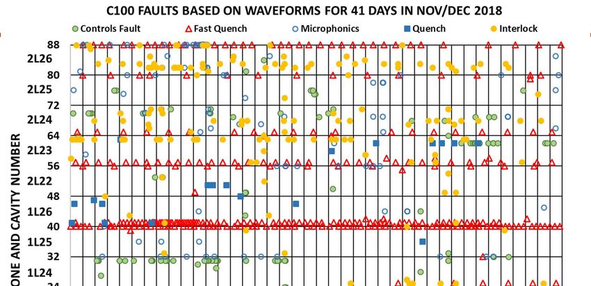
• Starting in the fall of 2016 the JLAB LLRF and EPICS software groups implemented
a waveform harvester for C100 cavities which was triggered by a cavity trip.
• In the spring of 2018 it was configured to synchronously trigger the waveforms for
all 8 of the cavities in a zone any time one of the cavities in that zone had a fault.
• The 14 waveform records per cavity are 8,000 points with typical record lengths of
400 ms or 1.6 seconds
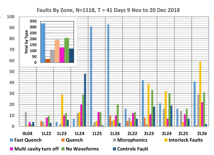
• For the spring of 2018 and fall of 2019 there were about 500 faults classified per
month.
C100 Faults, TTC Workshop, Feb. 2019 2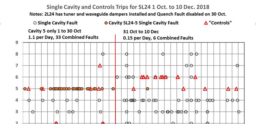
Types of faults, Microphonics Transient Burst

          RF Power (kW)

                                                   Gradient MV/m

          Gradient Drive (V)

                                                Detune Phase (deg)

•    Cryomodule is running along relatively quietly, microphonics‐wise with an excursion of +/‐ 20
     degrees in detune phase.
•    A burst of 80 Hz occurred at starting at about 230 mS
•    At about 300 ms the FCC output drive for cavity 1 (GASK) is clamped at 10; the klystron power is
     driven to its maximum; the phase gets lost and the cavity is driven towards zero.
•    At about 305 ms FCC‐1 switches to SEL mode and with constant forward power and the cavity is
     driven to about 12 kW
•    The transient in the cavity 1 gradient shakes the entire string (Lorentz detuning) coupling most
     strongly into cavity 2. This is followed by cavity 3, then 2 then 4 hitting the clamp; cavity 4 getting
     switched off and cavities 2 and 3 getting switched to SEL mode. This is a typical cascade of faults.
    C100 Faults, TTC Workshop, Feb. 2019              3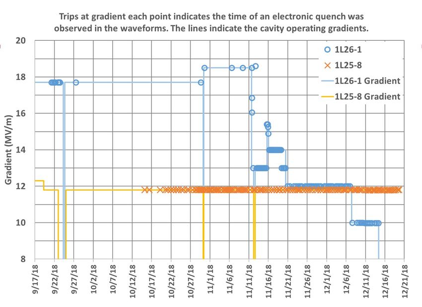
Is It Tuner Motor Induced?

•     Data taken using external DAQ module and analog outputs of FCC.
•     Upper traces are detune angle (DETA2) taken via analog output ports. Lower is signed tuner steps
      taken from EPICS. They are updated once per second.
•     Note quiet microphonics between 11 and 12 seconds when there is little if any tuner operation.
•     Note larger peak microphonics bursts when multiple tuners operate. Detailed analysis indicates
      that the microphonics bursts has a lot of 80 to 100 Hz content.

    C100 Faults, TTC Workshop, Feb. 2019           4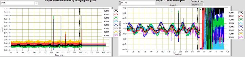
Fast Quench
•     Fall time of cavity gradient faster than 50 us (one point at
      this acquisition rate).
•     Cavity seemed to be operating normally up until this point.
•     Vacuum burst in cavity releases large quantities of
      electrons which absorb the energy within the cavity.
•     In this event both cavity 1 and 2 had the same type of
      event at the same time. Normally they were all single
      cavity events, which were dominated by the cavities at the
      ends of the cryomodules.
•     The hypothesis is that these are waveguide vacuum
      discharges in the cold to warm transition.

                 2e‐5 Torr
                                                           •       Corresponding beamline vacuum excursion.
                                                           •       Red trace is pump next to cavity 1 blue trace is at
                                                                   the upstream end of the girder.
                                                           •       Peak vacuum signal adjacent to cavity 2e‐4 Torr at
                                                                   the other end of the girder was 3e‐7 Torr.
                                                           •       No events were recorded where cavity 1 in one
                                                                   zone and cavity 8 in the adjacent zone had the
                                                                   same fault at the same time which indicates that
                                                                   the event was not due to a vacuum burst in the
                                                                   girder between the cryomodules.

    C100 Faults, TTC Workshop, Feb. 2019                       5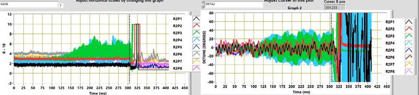
End Group Driven Quench (Most Probably)

                                                                                               Time of
                                                                                                 Trip
                                                                                                15:42
                                                                                                16:27
                                                                                                17:03
                                                                                                17:11
                                                                                                17:28
                                                                                                17:36
                                                                                                18:59
                                                                                                19:09

•   8 very similar trips where the detune phase (cavity frequency) walked up in value for a few hundred
    ms before the RF system ran out of power. Typically the indicated fault was a gradient error fault.
    After the last trip the operators reduced the gradient by 0.5 MV/m and the trips stopped.
•   It is suspected that this is an end group quench which based on practical experience and
    simulations done by Ed Daly takes a few hundred ms to a few seconds to fully propagate.
•   This is compared to a prompt (in the cell) quench which has a propagation time of 3 to 5 ms.

    C100 Faults, TTC Workshop, Feb. 2019           6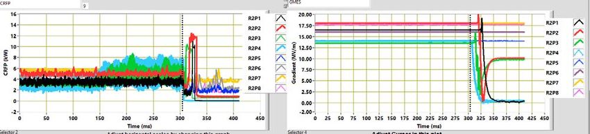
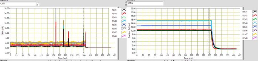
Single Cavity Interlock Trip

• Zone running fine and at about 300 ms cavity 3 trips off going to a zero RF power even
  while GASK is not at zero. This is an indication that the RF switch was open.
• The gradient decays with a nominal turn off decay time.
• Detailed analysis of the archived fault data indicated that >90% of these faults are
  quench faults (QNCH) detected by the field control chassis.

 C100 Faults, TTC Workshop, Feb. 2019       7
Examples of Controls Faults

                                           •   Loop oscillations
                                               probably due to
                                               incorrectly set loop
                                               phase.

                                           •   4.2 kHz loop oscillations
                                               on one cavity probably
                                               shaking the adjacent
                                               cavity

                                           •   “Single Event” noise.

                                           •   Although it could be do
                                               other sources these trips
                                               occurred frequently
                                               during thunderstorms
                                               mostly in the south linac.

C100 Faults, TTC Workshop, Feb. 2019   8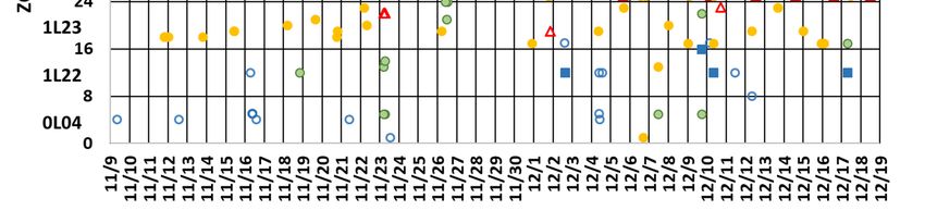
One I Do Not Understand

• The zone was operating fine and cavity 4 decides that it was going to detune 70 degrees
  in 6 ms often these types of events happen in 2 or 3 ms.

• I do not think that it was a prompt (in the cells) quench or it would not have recovered
  to SEL mode.
 C100 Faults, TTC Workshop, Feb. 2019        9
Confirmed “Anomalous” (no more) Quench Event

•    Typical cascade trip initiated by cavity 4 being 40 degrees off crest and improperly tuned by an extra 4 degrees.
•    The step at 299 ms is due to the beam turning off. It is the corresponding step in DETA2 is because the real part
     of the cavity drive contains the beam current term and the imaginary part contains the cavity detune
     component.
•    As the FCC loses control due to clamping GASK cavity 4 is driven down in gradient and cavities 2 and 3 are driven
     up in gradient.

    C100 Faults, TTC Workshop, Feb. 2019                  10
Quench Driven by RF Transient
0‐10
kW
• Cavity 2 is driven to 22.5 MV/m by a “lost” control loop.
• With beam off (300 ms) Cavity 2, Forward Power of 2.1 kW at 19 MV/m.
• The RF switched off just after 312.5 ms when the cavity was at 20 MV/m which should have had an
emitted power of 9.3 kW.
• The indicated emitted power value was about 7.7 kW.
• Testing in CW the next day indicated a prompt quench field of 22.5 MV/m.
• Thus, in this case, the anomalous quench was really a quench driven by the control system losing
control.
C100 Faults, TTC Workshop, Feb. 2019 11C100 Faults, TTC Workshop, Feb. 2019 12
C100 Faults, TTC Workshop, Feb. 2019 13
•   We bypassed the quench fault in the FCC and used the gradient error interlock in its place and
      were able to reduce the faults of this type by a factor of 7.
  •   We spread a variation of this out to 4 zones at the beginning of this run and should have
      statistics in a few weeks.
C100 Faults, TTC Workshop, Feb. 2019            14
• Electronic quenches turned on in 1L25‐8 on 20 Oct. and in 1L26‐1 on 11 Nov.
• We reduced the gradient in 1L26‐1 from 17.5 to 10 MV/m and are still experiencing one trip per shift.
• We are concerned that this indicates a leak in the girder between zones 1L25 and 1L26.
• We cryo‐cycled to 30 K to see if the problem is residual hydrogen or helium.
• We will be watching carefully during the current run.
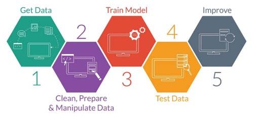
C100 Faults, TTC Workshop, Feb. 2019 15Machine Learning for SRF Cavity Fault Classification
Train a model to correctly classify the type of RF fault given waveform data
1. Get Data: automated way of recording data
6
2. Clean, Prepare & Manipulate Data: label data
3. Train Model: the “easy part” (Python’s ML library)
4. Test Data: quantitatively check performance
5. Improve: feature and algorithm selection
6. Predict: test on unseen, unlabeled data Predict
Train Many Models
Initial Results Promising
overfitting
Visualizing Decision Tree
• Initial run took several days to process data.
• Follow‐up runs use the most promising metrics will be
much faster.
• Initial efforts by Chris Tennant, other team members
include Anna Solopova and Yves Roblin.
C100 Faults, TTC Workshop, Feb. 2019 16Summary and Future Work
Summary:
• We are able to better classify faults and identify the offending cavities when there is a cascade
of faults.
• We are using the identified faults to improve the LLRF driven interlocks and to better
understand the state of the machine.
• We are using fault statistics as a major input as to where to focus our improvement efforts.
Future Work
• Continue to monitor faults manually and develop a guide for operations.
• Develop machine learning tools to take the human out of the initial fault identification loop.
• Use the data to focus efforts on
- Eliminating false trips,
- Knowing which cavities to turn up/down
- Identifying other remedial actions.
• Better understand fast quenches which are vacuum discharges on the cavity side of the (warm)
cavity window.
Acknowledgements
I would like to thank Anna Solopova for pushing to get the waveform harvester functional and
managing the C100 cavity operational parameters. LLRF and EPICS software groups for
implementing and maintaining the harvester. Curt Hovater, Clyde Mounts, Rama Bachimanchi,
Tomasz Plawski and many others for their time in discussing and understanding the faults.
C100 Faults, TTC Workshop, Feb. 2019 17BACKUP SLIDES C100 Faults, TTC Workshop, Feb. 2019 18
Anomalous Quench as Seen in EPICS

                              Liquid Level

• Liquid level oscillation indicates heat riser choke with more than about 50 W of
  dissipated power. Multiple cavities tripped off.
• We were seeing what were interpreted as thermal quenches in the cavities at
  gradients substantially below the prompt quench fields in the cavities.
• Unlike the end group driven quenches shown previously these quenches occurred
  randomly.

C100Title
Talk Faults,
          HereTTC Workshop, Feb. 2019        19
Wandering around the wavforms.
Zone Selector Trip Selector, next,
previous or randomly Directory name with trip time in Detune angle, DETA2,
YYMMDD_HHMMSS.s format. is a measure of
selected
Microphonics
deltaF α Tan(DETA2)
Time in ms Signal Name Selector (4 places) Channel On/Off Selector
DETA2 = Pfwd(Phase) – PTrans(Phase) – TDOFF => zero when cavity is at machine frequency.
GASK requested FCC output “voltage” 0‐10, CRFP forward power, CRRP Reflected Power, GMES Gradient.
C100 Faults, TTC Workshop, Feb. 2019 2020You can also read