Can one predict a drop contact angle? - arXiv
←
→
Page content transcription
If your browser does not render page correctly, please read the page content below
Can one predict a drop contact angle?
                                                 Marion Silvestrini∗,1,2 , Antonio Tinti2 , Alberto Giacomello2 , Carolina Brito1
                                                     1
                                                     Instituto de Física, Universidade Federal do Rio Grande do Sul, Av.
                                                         Bento Gonçalves 9500, CEP 91501-970, Porto Alegre, Brazil
                                                 2
                                                   Dipartimento di Ingegneria Meccanica e Aerospaziale, Università di Roma
arXiv:2109.11040v1 [cond-mat.soft] 22 Sep 2021

                                                                       “La Sapienza”, 00184 Rome, Italy

                                                                                       September 24, 2021

                                                                                              Abstract
                                                              The study of wetting phenomena is of great interest due to the multifaceted
                                                          technological applications of hydrophobic and hydrophilic surfaces. The theoretical
                                                          approaches proposed by Wenzel and later by Cassie and Baxter to describe the
                                                          behaviour of a droplet of water on a rough solid were extensively used and improved
                                                          to characterize the apparent contact angle of a droplet. However, the equilibrium
                                                          hypothesis implied in these models means that they are not always predictive of
                                                          experimental contact angles due to strong metastabilities typically occurring on
                                                          heterogeneous surfaces. A predictive scheme for contact angle is thus urgently
                                                          needed both to characterise a surface by contact angle measurements and to design
                                                          superhydrophobic and oleophobic surfaces with the desired properties, e.g., contact
                                                          angle hysteresis. In this work a combination of Monte Carlo simulation and the
                                                          string method is employed to calculate the free energy profile of a liquid droplet
                                                          deposited on a pillared surface. For the analyzed surfaces, we show that there is
                                                          only one minimum of the free energy that corresponds to the superhydrophobic
                                                          wetting state while the wet state can present multiple minima. Furthermore, when
                                                          the surface roughness decreases the amount of local minima observed in the free
                                                          energy profile increases.

                                                     ∗
                                                         email:   marion.silvestrini@ufrgs.br

                                                 1       Introduction
                                                 Contact angle is perhaps the most immediate way to characterise the wettability of a
                                                 given surface, due to the ease of depositing a drop and estimate the angle formed by it.
                                                 Indeed, the Young equation allows one to relate the surface tensions with the contact
                                                 angle on an ideally smooth surface [1]. However, the crucial question is whether this
                                                 observable is a reliable one in the case of actual surfaces, in which heterogeneities are
                                                 inevitably present.
                                                     Surface heterogeneities can dramatically change the contact angle as compared to the
                                                 case of an ideal, homogeneous surface. In particular, topographical heterogeneities tend

                                                                                                  1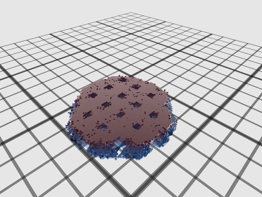
to magnify the intrinsic wettability of the surface, making them “superhydrophobic” or
“superhydrophilic” [2]. Since the pioneering work of Wenzel [3] and Cassie and Baxter
[4], the concept of apparent contact angle has been used, which is meant to predict the
angle measured at the actual surface accounting for the effect of both wettability and
heterogeneity. Since then, a continued effort has been spent to provide accurate models
for predicting the apparent contact angles based on the chemical and topographical char-
acteristics of the surface. The main ambition of this line of research is finding a rapid and
inexpensive way to characterise surface wettabilities via contact angle measurements.
    The standard approach to develop wetting models for heterogeneous surfaces consists
in assuming a wetting state of the surface and predict the contact angle based on the
homogenised surface energy of such composite interface. The task becomes more involved
when a surface allows multiple visibly different states, e.g., for superhydrophobic surfaces
in which the roughness can be fully wet (Wenzel, W) or dry (Cassie-Baxter, CB).
    Importantly, major difficulties arise in relating the apparent contact angle and surface
characteristics, most importantly due to static contact angle hysteresis (CAH), i.e., a
scatter of the contact angle values which depends on the experimental procedure or
history. Already in 1964, Johnson and Dettre [5] showed that an idealised sinusoidal
roughness can be an important source of CAH; they further showed that the W state is
connected to larger CAH than the CB state. More recent work further showed that CAH
emerges from micro and nanoscale phenomena which are beyond the scope of Cassie and
Wenzel equations [6]. A heated debate originated from the question whether “Cassie and
Wenzel were wrong” [7, 8, 9]. The main merit of such discussion was to highlight that
the experimental contact angle may be determined by features localised at the three-
phase contact line where the drop meets the surface. In fact, the classical CB and W
models assume an equilibrium hypothesis in which the droplet is allowed to relax to the
absolute free energy minimum. In other words, due to the rough free energy landscape
featuring multiple minima, the measured contact angle may significantly depart from the
value predicted based on averaged surface characteristics and the commonly used wetting
models [10, 11, 12].
    Several attempts have been made to relate the characteristics of single defects to CAH,
starting from the pioneering work of Joanny and de Gennes [13, 14, 15, 16]. However,
densely packed heterogeneities [17], together with the finite size of the drop and the
multiple wetting states possible on superhydrophobic surfaces [18, 19, 20, 21, 22, 23]
considerably complicates the matter. Indeed to date, notwithstanding the theoretical and
practical importance, the analysis of the free energy landscape connected to wetting of a
realistic surface by a droplet is still lacking. Thus making a connection between measured
contact angles and available wetting models is highly needed in the community. At the
same time, the difficulties connected to the exploration of rough free energy landscapes
[24] represent a major obstacle to develop the computational tools required for engineering
textured surfaces with the desired wetting properties. In this work, we fill such a gap,
providing a generic framework for reconstructing the free energy connected to wetting
of a pillared superhydrophobic surface based on the combination of the cellular Potts
model [25] and the (zero temperature) string method for rare events [26, 27, 28]. This
approach allows us to assess the variation of CAH with the pillar spacing, to connect
CAH with the existence of multiple free energy minima, and to verify the energetic origin
of the superhydrophobicity of the CB state. In addition, the presented approach provides
useful guidelines for contact angle measurements on actual surfaces and for designing
surfaces with tailored wetting properties, notably superhydrophobic ones.

                                             2
The paper is organised as follows. In Section 2 we present the numerical setup used:
a Monte Carlo scheme combined with the string method. Section 3 contains the results
of the free energy calculations and the physical origin of its saddle points. In Section 4,
we discuss the origin of contact angle hysteresis and compare the CB and W models with
the simulations. The paper is then concluded in Section 5.
2 Numerical Model
The main aim of our simulation campaign is connecting the apparent contact angles
attainable on a given surface with its physical and chemical characteristics. We focus on a
hydrophobic surface decorated with a three-dimensional array of pillars with the geometry
shown in Figure 1-a. A three-dimensional spherical droplet with volume V0 = 4/3πR03
is placed over the surface. We use a mesoscale wetting model, the cellular Potts model
[25, 29, 30], which has been successfully used in studying the wetting of structured surfaces
[31, 32, 33, 34, 35]. Its low computational cost as compared to, e.g., molecular dynamics,
allows computations of relatively large 3D drops via Monte Carlo minimisation.
We combine the MC minimisation with the string method [26, 28] in order to cal-
culate the most probable path leading from the superhydrophobic CB to the fully wet
W state or vice versa. The string method, combined with atomistic simulations, dif-
fuse interface methods, or sharp interface models, has proven instrumental to clarify the
origin of metastability in wetting of structured surfaces [23, 36, 37, 38]. We will em-
ploy this approach to overcome the free energy barriers, to establish the mechanism of
breakdown/recovery of the CB state, and to identify intermediate minima.
(a) (b)
w
d=w+a w
z y
y x x
Figure 1: Sketch of the surface decorated with pillars. (a) Geometrical parameters
defining the texture: w is the pillar width, h is the pillar height, a is the interpillar
distance and d = w + a. (b) Top view of the surface. The blue region delimits one cavity,
used in the definition of the collective variables.
2.1 The cellular Potts model
The Cellular Potts model (CPM) assumes a three state system in a simple cubic lattice,
with each site representing a different state: solid, liquid, and gas. We employ this
technique to simulate a three-dimensional droplet in contact with air and a solid surface.
The Hamiltonian of the system is given by:
l=N
1X κX 2
H= Esi ,sj 1 − δsi ,sj + zl − zlT , (1)
2 2 l=1
hi,ji
3where si ∈ {0, 1, 2} is the state of a given site in the lattice, gas (G), liquid (L), or solid
(S). The first term on the right hand side describes the surface interaction between the
three states, with Esi ,sj = Jij · aL , where Jij is the site-site coupling between i and j type
sites, aL = L2 is the unit area and L is the lattice size. The summation ranges over the
nneigh = 26 nearest and next-nearest lattice sites of the 3D simple cubic lattice. Notice that
the energy contribution will be non-zero only when si 6= sj . Gravitational contributions to
the energy are neglected due to small size of the droplets hereby investigated [39, 34, 33].
The second term in Equation (1) corresponds to a harmonic bias used to drive the
system across metastabilities allowing to more effectively explore phase space [27] using
general descriptors, the collective variables z, which are function of the lattice sites. Bi-
asing is used because, in an unrestrained simulation (κ = 0), drops relax and remain
trapped in the closest minimum state. Simulation modeling a droplet deposited on a tex-
tured surface without any bias were previously studied in Refs. [33, 40], where the authors
indeed showed that the final contact angle depends on the initial wetting configuration.
The collective variables z that appear in Equation (1) should be chosen carefully [41]
in order to correctly discriminate among relevant configurations of the system. More in
detail z T represents the target value for the collective variable, while κ is stiffness of the
harmonic constraint. In this work we shall identify zl with liquid-phase occupation of
N interpillar grooves. The usage of such discrete density indicators is customary when
dealing with wettability problems [42].
The energy scale is set once Jij is defined. In this work spin-spin couplings are chosen
to render the same ratios between the interfacial surface tensions as in Ref. [43], in which
a droplet of water is studied on a surface composed by Polydimethylsiloxane (PMDS)
with the following surface tensions σij between the gas (G), liquid (L), and solid (S):
σGL = 70 × 10−3 N/m, σSG = 25 × 10−3 N/m, and σSL = 53 × 10−3 N/m; the last value
was calculated by Young’s equation, σGL cos θY = σSG − σSL with θY = 114◦ . The data
will be presented in dimensionless form using the lattice size L as unit length, aL = L2
as unit area, and JGL · aL as unit energy, referred as e.u. In such reduced units, JGL = 1,
JSG = 0.36, and JSL = 0.76. For the forcing parameter we use κ ' 0.004, which drives
the system to the target configuration while allowing some fluctuation. More details
about the choice of κ is reported in the Supporting Information (SI). In order to convert
the dimensionless units to physical ones, one can for instance assume L = 1 µm and the
energy for the gas-liquid interface of water, which yields σGL aL = 7 × 10⁻¹⁴ J.
To evolve the system we use the Metropolis-Hastings algorithm, which consists in
changing the state of two random sites at the gas-liquid interface with an acceptance rate
equal to min{1, exp[−β∆H]}, where β = 1/T is the inverse of the effective temperature
of the CPM, which introduces some noise, allowing for a more effective exploration of the
phase space. We set T = 4.8 throughout the article, which allows the system to fluctuate
with an acceptance rate of approximately 9%. The attempted MC moves consist in swaps
between liquid and gas sites, which guarantees that the volume of the droplet is constant
throughout the simulation.
2.2 The string method
In order to attempt a simulation of the wetting of rough surfaces it is crucial to tackle the
challenge associated with the presence of metastabilities. Previous methods to sample
rough free energy landscapes required projecting to a low dimensional representation
of the free energy as a function of a handful of parameters and reconstructing the full
4landscape as a function of such collective parameters. It is easy to understand how this
task requires a computational effort which is exponential in the number of collective
variables thus limiting the applicability of this class of methods typically to two/three
variables. Such low dimensional representation of the energetic landscape often results
in a poor description of the phenomena [41]. The (zero temperature) string method in
collective variables was first introduced by Vanden-Eijnden and collaborators [27] and is
a path method that requires only the computation of the local gradient of the free energy
landscape at certain points along the path; its computational cost thus only grows linearly
with the number of collective variables.
The string method allows for a fast and convenient identification of the minimum free
energy path (MEP) connecting two metastable regions of the rough landscape, along with
providing a measure of the free energy along the path, without requiring to fully sample
a high dimensional variable space. This is achieved by iteratively refining a discretized
guess path (i.e., the string). In this work the collective variables (CV) represent the liquid
occupation of each cavity, as represented by the blue region in Figure 1-b. The available
volume in the cavity is given by (d2 − w2 )h. The algorithm proceeds as follows:
T
1. We run Nr Monte Carlo (MC) replicas, each biased to explore the vicinity of a zl,i
point in the collective variable space. Each replica corresponds a string point in the
collective variable space.
2. The Nr replicas run for 105 MC moves allowing to sample the mean biasing forces
and the local free energy gradient at each string point.
3. The string is updated by a convenient gradient descent of the string points and
T
reparametrized [28] so that one has a new set of zl,i . The process is iterated from
point 1.
Refinement of the initial string guess is repeated until convergence is reached, as
evaluated by a suitable threshold in the changes to the path/path energy. In all runs
convergence was obtained within 20 iterations. At convergence, numerical integration of
the free energy gradients allows for the reconstruction of the free energy profile along the
string:
j l=N
X X
T T
∆Fj = −κh(zl,i − zl,i )i∆zl,i , (2)
i=1 l=1
T
with ∆Fj the free energy at point zl,j , the index l running over the N collective variables,
T T T
i up to the current replica j, with j ≤ Nr − 1, and ∆zl,i = zl,i+1 − zl,i . The results
shown in this work are averages over the distinct realizations of the simulation and h. . . i
represents the average over MC steps.
3 Results
We consider three substrates with same pillar height h = 10L and width w = 5L and
different distances between pillars: substrate referred to as S1 presents a low interpillar
distance (a = 5L), S2 an intermediate value (a = 8L), while S3 has the largest interpillar
distance (a = 11L). The volume of the spherical droplet is defined by imposing an initial
radius of R0 = 50L. We first show the rough free energy landscape connected with
wetting of the three surfaces, characterizing the droplet configuration at the minima and
5maxima of the free energy. We then introduce a possible physical explanation of the
roughness in the free energy and end this section discussing the connection between the
free energy landscape and contact angle hysteresis.
3.1 Rough free energy of a hydrophobic pillared surface
Figure 2-a reports, for substrates S1 , S2 , and S3 , the free energy of the drop as a function
of the total filling of the cavities below the drop, which is defined as the sum
P of the target
filling of each cavity divided by the total volume of the droplet: f = l zlT /V0 . The
minima in the free energy correspond to stable (global) and metastable (local) states of
the system. The free energy extrema are numerically identified from the data; minima are
indicated in Figure 2-a as black circles, while maxima by red triangles. Since some minima
are very shallow and may be affected by numerical accuracy we performed numerical MC
minimisation using different initial conditions close to the putative minima, to confirm
that the system can indeed reside in such states; empty symbols denote shallower minima
which will not be further discussed. Figure 2-b shows the fraction of water wetting
the bottom area. The vertical dotted line in the figure roughly separates two regimes:
on the left, the liquid does not touch the bottom of the substrate, indicating that the
corresponding configurations of the droplet are associated to the superhydrophobic CB
state, while, on the right of the line, the liquid reaches to the bottom of the substrate
and the droplet configurations are associated with the wet W state(s). Importantly, the
free energy landscape appears rough for all considered surfaces, with markedly different
trends for the three interpillar distances: monotonically growing for S1 , almost at the CB-
W coexistence, with additional high free energy minima, for S2 , and with a significant W
basin with multiple local minima for S3 .
615000
CB W (a)
states states
VIII
10000
II
IX
WE
III' III ' VII (a)
states
5000
VII' '
0.03 0.06 0.09 0.12 0.15 0.18
Filling (%)
0
I II IV S1
VI
S2
III V VII S3
(b)
Fraction of bottom
0 0.03 0.06 0.09 0.12 0.15 0.18
area wetted
0.2
Filling
0.03 0.06 0.12 0.15 0.18
0.1
Filling (%)
(b)
0
0 0.03 0.06 0.09 0.12 0.15 0.18
Filling f
(c) I III V VII
Minima S3
II IV VI
Maxima S3
z
x
Figure 2: (a) Free energy profile as a function of the liquid filling the cavities for the
three substrates. Minima are identified with black circles and maxima by red triangles;
empty symbols denote very shallow minima (and related maxima) in which the system
does not remain after standard MC minimisation. (b) Fraction of the bottom area of the
substrate in contact with the liquid, normalized by the total substrate area. (c) Lateral
view of the minima and maxima in the wetting of substrate S3 . The inset in (a) defines
the left and right barriers, H L and H R , respectively.
Each point on the free energy profiles corresponds to a droplet configuration, whose
sequence thus defines a wetting path, see Figure 2-c; in particular, these paths represent
the most probable way in which the transition from CB to one of the various W states (or
vice versa) occurs. Other paths may exist connecting minima, especially in such complex
landscape, see e.g. Ref. [44]. Figure 2-c presents a lateral view of the 3D droplet in
correspondence of the minima and maxima of substrate S3 . Minimum I corresponds to
the CB state, with air trapped between the pillars – this numbering is the same for the
three substrates. As the droplet starts infiltrating the substrate, it touches the bottom for
the first time at point II, where free energy increases to a maximum. A similar behaviour
was also reported in molecular dynamics simulations [23, 45, 46, 47]. As the filling level
increases, the free energy of the substrate presents several local minima which correspond
to the progressive infiltration of liquid within the pillars: lateral views of the droplet in
Figure 2-c clearly show full wetting of 3 lines of cavities at minimum III, 4 lines at V, 5
lines at VII. For filling levels above 7 lines of cavities, the free energy does not present
any other minima for this droplet size.
The maxima separating the mentioned minima are found to be associated to an in-
complete wetting of some of the cavities at the drop perimeter; we will further analyse
7their origin in Section 3.2. We note that the wetting of the substrate in 3D is a more com-
plex problem than what can be inferred from a lateral view, which is however convenient
to picture the main features of the process; we thus make available in the Supporting
Information videos in 2D and 3D of the droplet wetting the 3 substrates.
The inset of Figure 2-a defines the barrier H L , which is the difference in ∆F between
a minimum and the consecutive maximum on its left and H R , being the difference in
∆F between a minimum and the first maximum on its right. Using these definitions,
we found that the barrier H R and H L are typically of the same order of magnitude for
substrate S3 , while for S1 H L
H R . We will come back to this point later.
These observations raise several questions, which are addressed in the next section:
why some substrates present global minima at the CB state and others in the W con-
figuration? What is the physical origin and significance of the local minima and the
intervening maxima?
3.2 Physical origin of the minima and maxima of the free energy
The wetting state corresponding to the global free energy minimum is different for the
considered substrates and can be rationalized using a continuous global energy model [33].
This model takes into account the energy of creating interfaces between the liquid, the gas,
and the solid of a spherical droplet with fixed volume V0 placed on a surface. The droplet
is allowed to display two wetting states: it either stays in the superhydrophobic CB state
or it homogeneously wets the surface in the W state. We refer to these configurations
as ideal Cassie-Baxter, CBI and ideal Wenzel, WI , states. The difference in energy of a
system with and without the droplet on the surface can be written as [33]:
I
∆E CB 2
= σGL SCB − πBCB (φS cos θY − (1 − φS )) , (3)
WI 2
∆E = σGL SW − πBW r cos θY , (4)
where Ss = 2πRs 2 [1 − cos(θCs )] is the surface of the spherical cap in contact with air,
B s = Rs sin(θCs ) is the base radius, Rs the radius of the droplet, and θCs its contact angle
in the state s. φS = w2 /d2 is the fraction of solid surface area wet by the liquid (or pillar
density) and r = 1 + 4wh/d2 is the surface roughness ratio.
The main difference between the model defined by Equation (4) and the Wenzel one [3]
is that the former one considers a droplet of finite size, which means that the interface of
the cap and the lower interface in contact with the substrate compete in the minimisation
of the total free energy. We will return to this point in Section 4. Concerning the CB
state, it is instead found that results are equivalent when one explicitly considers the cap
as in Equation (3) or simply homogenises the surface free energy as in the original CB
theory [4].
Figures 3-a and b show lateral views of droplets minimising the equations of the ho-
mogenised model and ∆F obtained by MC simulations for surface S1 and S3 , respectively.
∆F of the surface S1 presents only one minimum for which the simulated configuration
is shown in blue together with the minimum of the solution of Equation (3), in red. ∆F
of surface S3 has multiple minima and two of them are represented in Figure 3-b: the
local minimum at the CB state, shown on top with the solution of Equation (3), and the
global W minimum reported in the bottom panel, in which is compared with the solution
of Equation (4). Results are in good agreement for the CB state, both concerning the
contact angle and the number of intruded cavities. On the other hand, contact angles
8are not in perfect agreement for the W state, due to the local pinning at pillars, which
is not captured in Equation (4), see below for details. On the other hand, the model
predicts correctly that W is the global free energy minimum and the free energy values
are in reasonable accord, see the Supporting Information.
(a) (b) (c)
IV
1
4
Height
7
VII
10
Figure 3: Homogenised model vs ∆F. (a) Side view of configuration at the minimum of
∆F for surface S1 in blue. Red dashed line is the numerical solution of the homogenised
model for the CBI state, Equation (3). (b) Top: side view of a sessile droplet on surface
S3 at the local minimum of ∆F (point I in Figure 2) and the solution of Equation (3).
Bottom: global minimum of ∆F in the W state (point VII in Figure 2). The blue solid
line is the numerical solution of the model in Equation (4) for the WI state. (c) View
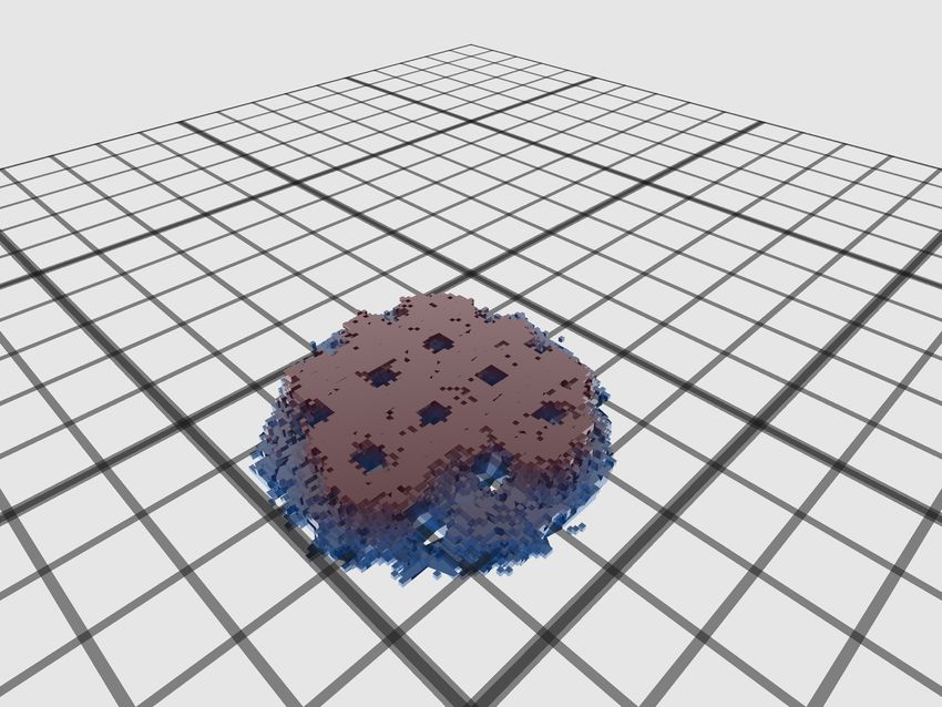
from below of the 3D configuration of the droplet placed on S3 at two filling levels: point
IV in Figure 2-a (maximum) and point VII (global minimum); colors correspond to the
height of liquid in each lattice site.
Besides the fair agreement at the global minimum, the main difference between the
two approaches is that the simulated free energy profile presents several local minima
which are not accounted for in any homogenised model. This difference is particularly
important for the W state, which helps to explain the difference in the global W minimum.
Indeed, an important simplification introduced in the model (4) is that the W state is
achieved by homogeneous wetting: below the droplet base, there is a perfect cylinder
filling the cavities; individual wetting of pillars is thus disregarded; the cost to create the
interface between the liquid and air is also neglected in the model. However, simulations
show that the infiltration of the substrate is not homogeneous, that pinning at individual
pillars may occur, and that the interface between the liquid and the gas below the droplet
is quite rough, as exemplified in Figure 3-c for one minimum and one maximum: the
configurations are particularly far from being a cylinder when ∆F is at a maximum.
The nontrivial shape of the droplet in contact with the surface drove us to investigate
the contribution to the free energy of each interface. We propose a putative free energy
defined as: Ω = ∆P V0 + σGL AGL + σSL ALS + σSG ASG , where ∆P can be interpreted as the
Laplace Pressure, ∆P = −ασGL with α being the mean curvature of the drop and Aij
are the interfaces between two different phases ij (solid, liquid, and gas). We then use
the Young equation σSG = σSL + σGL cos θY to rearrange the terms and note that the total
area of the substrate Atot = ALS + AVS is constant. The contribution of liquid-gas surface
area AGL is split in two parts, one corresponding to the surface of the spherical cap ACGL ,
and other to the part below the droplet, ABGL . We can then write the difference in free
9energy with respect to the reference one Ωref = σSG Atot :
∆Ω = σGL (ACGL − αV0 + ABGL − ALS cos θY ) . (5)
Interestingly, the surface tension σGL factorises and only geometrical quantities appear in
the parenthesis on the right hand side, together with the contact angle θY .
Figure 4-a compares, for surface S3 , the free energy ∆F obtained in the MC simu-
lations via Equation (2) with the putative free energy ∆Ω always computed from MC
simulations but by measuring the geometrical quantities in Equation (5). In particular,
the surface areas Aij and the mean curvature α = 2/R are measured from droplet configu-
rations along the converged string. Since the free energy ∆F is computed by integration,
it is known up to a constant and thus can be freely displaced along the y-axis. The only
free parameter left to compare ∆Ω to ∆F is σGL , which should be of the order of the
coupling parameter Jij .
Figure 4-a shows ∆F and ∆Ω using σGL = 1, which is the same value used for Jij .
The two quantities show similar trends and are in semi-quantitative agreement for all
three substrates analysed in this work (see the Supporting Information for the other two
substrates). Interestingly, the ruggedness observed in ∆F is also present in ∆Ω.
In Figure 4-b each geometrical term in Equation (5) is shown separately and compared
with ∆F. Note the different scales and units for areas (right axis) and ∆F (left axis).
Most of the interfacial areas show a smooth dependence on f , the exception being ABGL
that presents some maximum and minima which is thus a good candidate to explain the
roughness of the free energy connected to wetting.
10(a) 6000
0000 ∆F
corr1.5-s 2.7 40000
3000
0000 30000
0
0000 20000
-3000
0000 0 0.03 0.06
10000 0.09 0.12 0.15 0.18
(b) 6000
40000
0
014000 30000
ALS
0
3000 0.03 0.06 0.09 0.12 0.15
-10000 20000
12000
0.09 0.12
0
0.15 0.18 10000
Filling
10000 0
-3000
0 0.03 0.06 0.0980000.12 0.15 0.18
(c) 6000 8000
6000
6000
3000
4000 4000
0
0.12 0.15 0.18
2000
-3000
0 0.03 0.06 0.09 0.12 0.15 0.18
Filling
Figure 4: ∆F, ∆Ω and areas as a function of f for S3 . (a) Comparison of ∆F and ∆Ω.
(b) Each geometrical term in Equation (5) is shown separately and compared with ∆F
in blue. (c) ∆F in blue and ABGL is shown in black. The red curve is a linear fit of ABGL
and the red vertical lines indicate the area variations discussed in the main text. Dashed
lines denote the maxima of ∆F.
In Figure 4-c we show ABGL and ∆F to assess the importance of the former in the free
energy. Vertical dashed lines correspond to maxima of ∆F. We observe variations in the
curve of ABGL that are indicated by vertical red lines. The typical size of these variations is
∆ABGL ≈ 1000L2 . In terms of dimensionless energy, this corresponds to ∆ABGL σGL ≈ 1000.
This energy variation is comparable to the free energy barrier for S3 , ∆ABGL σGL ≈ H R ,
which suggests that the term relative to the interface between liquid and gas below the
droplet plays an important role in generating local minima in the free energy. For S1 ,
instead, abrupt variations of ABGL are not sufficient to generate local minima, due to the
steep slope of ∆F vs f , see the Supporting Information.
11In the previous section, we mentioned that local minima of ∆F correspond to pinning
of the drop at the pillars edges, which gives rise to several possible minimal configurations
characterised by different numbers of pillars. To connect this picture with the observation
that variations of ABGL correlate with variations of ∆F, we suppose that the wet domain
below the droplet can be approximated by a cylinder of height h and increasing radius
B, such that ABGL = 2πhB. This approximation does not take into account the roughness
of ABGL shown in Figure 3-c, but is reasonable in the case of minima. From the volume
differences between neighbouring minima in Figure 4 we can thus compute the jump in
droplet radius ∆B in the cylindrical approximation, ∆B ≈ ∆ABGL /(2πh) ≈ 16L. The
estimated value of ∆B corresponds to the typical size of a cavity d = w + a, which is
plausible and supports the idea that local minima correspond to jumps of the droplet
front across discrete numbers of pillars.
To summarize, we propose that the global minimum of the free energy corresponds
to configurations that minimise the total interfacial energy for a droplet of fixed volume.
Local minima, instead, occur in correspondence of abrupt variations of the liquid-vapor
interface below the droplet connected with the overcoming of individual pillars.
3.3 Minima of the free energy and contact angle hysteresis
We now evaluate the free energy barrier sizes that separate the local minima and the
consequences on the metastability of the substrates. In Figure 2-d, the barriers H R and
H L are defined. From Figure 2-a, one measures for S1 typically H R ∈ (3000, 9000) and
H L ∈ (0, 100) showing that, even when the system is initialised in a W-like state, it
rapidly evolves towards the CB minimum. For substrate S3 both barriers vary typically
in the range H R ≈ H L ∈ (370, 3700), which in physical units are between 9 × 10⁻¹² J
and 9 × 10⁻¹¹ J, assuming L = 1 µm. This is much higher than the thermal energy
kB T ≈ 4.1 × 10⁻²¹ J at ambient temperature: thermal fluctuations are not sufficient to
drive the system from one minimum to the other. Only other larger sources of energy
can move the drop away from local minima, e.g., mechanical vibrations.
When the system is prepared with some generic initial condition, it will fall in the
closest minimum and remain trapped there; this was verified by running unrestrained
MC simulations from several points along the curves in Figure 2-a. Only for the S1
the system always returned to the superhydrophobic CB state, even though two shallow
minima were identified numerically; this can either be due to the numerical accuracy of
the free-energy profiles or to the size of the barriers, which is so low that the fluctuation
imposed by the effective temperature of the Monte Carlo simulations are enough to bypass
them. In other words, the free energy profiles in Figure 2 help understanding the origin
of contact angle hysteresis in contact angle measurements, which can be rationalised in
terms of a rough free energy landscape with multiple minima, separated by large free
energy barriers. Furthermore, the importance of the initial conditions becomes apparent,
which correspond to the preparation of the sessile drop experiment.
Finally, the profiles account for the superhydrophobic properties of the CB state,
which are connected to the existence of a single minimum, i.e., with low hysteresis. On
the other hand, the presence of multiple W minima explains why CAH is so pronounced
in this wetting state and its stickiness [6, 49, 48]. Figure 5 shows the apparent contact
angle θC of the droplet measured in MC simulations together with ∆F for substrate S3 .
The fact that there is a basin of Wenzel states and that each minimum has a different
contact angle allows us to define the contact angle hysteresis θH related to the wet W
12state as the difference in θC of the configuration associated to the first and the last local
minimum of ∆F, see Figure 5. Table 1 summarizes the values θH for the three substrates
together with their roughness ratio r. We measured an increase of θH when r decreases,
which is in line to what was previously observed [50].
160
6000
150
140
3000
130
0 120
110
-3000 100
0 0.03 0.06 0.09 0.12 0.15 0.18
Filling
Filling f
Figure 5: Wetting free energy and apparent contact angles as a function of liquid filling
for substrate S3 . The scale on the left corresponds to ∆F and, on the right, to θC . The
difference between the θC associated to the first and last local minimum (indicated as
black circles) is defined as the θH .
Substrate roughness ratio, r θH , (in ◦ )
S1 3 0
S2 2.2 24◦
S3 1.8 36◦
Table 1: Contact angle hysteresis θH and roughness ratio r for the considered substrates.
4 Discussion: modeling rough wetting
We have identified by free energy simulations that some pillared substrates present several
local minima separated by high barriers, while others present only one minimum. Inci-
dentally, for tall/tightly packed pillars only the superhydrophobic CB state is possible,
while for more sparse pillars multiple local wet minima arise. The latter surfaces thus
display a behavior which is strongly dependent on the initial conditions: if a droplet is
deposited on a substrate at a random configuration, it would accommodate in a wetting
state correspondent to the closest minimum which can be either superhydrophobic or
sticky. The present findings also imply that theories that predict a single W state cannot
be complete [2].
We measured all apparent contact angles θC of the droplet in configurations corre-
spondent to physical minima identified in our simulations for the three substrates and
compared them with theoretical models, see Figure 6. Squares corresponds to the super-
hydrophobic CB minimum and circles to wet W states. Lines are solutions of the classical
13Cassie-Baxter and Wenzel models, whose apparent contact angles are given by:
cos θCCB = φS cos θY − (1 − φS ), (6)
cos θCW = r cos θY . (7)
For the case where the global minimum is CB, which happens for substrate S1 , Figure 6
shows that the prediction of the Cassie-Baxter model is almost quantitative. The CB
model also has a reasonable agreement with simulated θC in cases where it is only a
local minimum, which happens for substrates S2 and S3 . The agreement with CB model
deteriorates as the pillar distance increases, which can be explained by the increasing
curvature of the menisci suspended among pillars, not accounted for in the classical CB
model.
In principle, no direct comparison can be made between the W model and the MC
results, mainly because the model predicts only one state, while simulations demonstrate
the existence of multiple wet states. However, a fair comparison can be made considering
only the global minimum, which is compatible with the minimisation procedure used in
all homogenised models. It is seen that the W model prediction is far from the measured
contact angle and, for S2 , it even predicts a contact angle higher than the actual CB one.
When the finite size of the droplet is taken into account, as done in Equation (3) and (4),
the solution for the CB does not change but the W curve shifts to smaller values. This
simple correction captures the overall trend with interpillar distance and improves the
agreement with the global minima, although it is not quantitative. However, we remark
that the finite size is not enough to account for the existence of multiple minima, which is
due to pinning at individual pillars and is crucial to account for contact angle hysteresis.
Figure 6 confirms that the extent of CAH has the following trend S1 < S2 < S3 , which
suggests that the more favorable the W state, the higher θH . This trend is related to the
number of local minima and to the facility of wetting the bottom of the surface for short
pillars, but what limits the total number of minima still remains an open question.
160
0
Contact angle , Tc (in o)
0 140
0
120
Homogenised
Continuos CB
mode l, Eq.3
0 Homogenised
Continuos W
mode l, Eq.4
CB l,model
CB mode Eq.6
100 W l,model
W mode Eq.7
5 65 76 8 7 9 8 10 9 11 10 11
Inte rpillar dis tance , a (in tance
Inte rpillar dis L) , a (in L)
Figure 6: Apparent contact angle computed at physical minima in Figure 2 as a function
of the distance between pillars. Squares are θC of the CB state, circles for the W minima;
the open circles denote the global W minimum. Orange lines are the solution for the
homogenised models: dot-dashed for CB, Equation (3), and dotted for W, Equation (4).
Black lines are the predictions of the classical models: dot-dashed for CB, Equation (6),
and dotted for W, Equation (7).
145 Conclusions
In this work, we have used a combination of the cellular Potts model [25, 33] and the
string method [26, 27, 28] to compute numerically the free energy ∆F of a droplet with
a fixed volume placed on surfaces decorated with pillars. The computed free energy
landscape for wetting the surface is found to be rough, with one minimum corresponding
to the superhydrophobic Cassie-Baxter state; depending on the pillar spacing, multiple
local minima can exist, associated with different wet Wenzel states. Free energy barriers
typically larger than the thermal energy are found, whose origin can be traced back to
pinning of the liquid-gas interface below the droplet at individual pillars. Wenzel minima
are characterized by an increasing number of filled cavities, corresponding to different
apparent contact angles. This scenario accounts for the strong contact angle hysteresis
of the W state(s), in which the final wetting state depends on the initial condition.
We have compared the apparent contact angles obtained in our in silico experiments
with the predictions of simple models, including the classical Cassie-Baxter [4] and Wen-
zel [3] ones. Results showed that the Cassie-Baxter model has a good prediction capacity,
which can be improved by considering the curvature of menisci overhanging surface tex-
tures. On the other hand, the prediction of the apparent contact angle cannot be made
by simple models in the W state effectively hindering the deduction of surface character-
istics from θC measurements. Actually, the problem of predicting θC in the W state seems
ill-posed and the relevant challenge is to assess its contact angle hysteresis, which can be
achieved only by detailed models.
An interesting and long-standing question is the possibility of predicting CAH [13,
14, 16], which was possible for individual surfaces within our approach. It is found that
the wider the pillars are spaced, the larger CAH. Our analysis suggests that larger drops
would have liquid enough to fill more cavities and thus the free-energy profile would show
even more local minima. What limits the total number of filled cavities and how these
local minima connect to CAH is however not clear and deserves to be investigated.
Finally, our findings suggest that, for a complete characterization of the wetting prop-
erties of a substrate, it is necessary to repeat sessile drop experiments several times for
different initial conditions. Moreover, the fact that free energy barrier between minima
are typically much larger than thermal fluctuations suggests that mechanical vibrations
of the substrate are necessary to drive the droplet across different minima. The amount of
mechanical energy necessary to reach different minima need to be evaluated by computing
the barrier sizes, which is possible with the methodology proposed in this work.
Supporting Information
The supporting information describes the algorithm used to find the thermodynamic
wetting state for droplet placed on the pillared surface. Its also presents the criteria
to adjust parameter κ and description of the videos available. Then there is a discus-
sion of the comparison between the free energy obtained from the simulation with the
Cassie-Baxter and Wenzel models. Finally the areas of the components for the proposed
analytical free energy are presented.
Acknowledgements
M. Silvestrini and C. Brito thanks CAPES and CNPq for financing this work. This
work has been supported by the project “Understanding and Tuning FRiction through
nanOstructure Manipulation (UTFROM)” funded by MIUR Progetti di Ricerca di Ril-
evante Interesse Nazionale (PRIN) Bando 2017 - grant 20178PZCB5. This research is
part of a project that has received funding from the European Research Council (ERC)
15under the European Union’s Horizon 2020 research and innovation programme (grant
agreement No. 803213).
References
[1] T. Young, Philos. Trans. R. Soc. London 1805, 95 65.
[2] D. Quéré, Annu. Rev. Mater. Res. 2008, 38 71.
[3] R. N. Wenzel, Ind. Eng. Chem. 1936, 28, 8 988.
[4] A. Cassie, S. Baxter, Trans. Faraday Soc. 1944, 40 546.
[5] R. E. Johnson Jr, R. H. Dettre, In Contact Angle, Wettability, and Adhesion, vol-
ume 43, 112–135. ACS Publications, 1964.
[6] M. Nosonovsky, B. Bhushan, Nano Lett. 2007, 7 2633.
[7] L. Gao, T. J. McCarthy, Langmuir 2007, 23, 7 3762.
[8] A. Marmur, E. Bittoun, Langmuir 2009, 25, 3 1277, pMID: 19125688.
[9] G. McHale, Langmuir 2007, 23, 15 8200.
[10] H. Y. Erbil, C. E. Cansoy, Langmuir 2009, 25, 24 14135.
[11] H. Y. Erbil, Surf. Sci. Rep. 2014, 69, 4 325.
[12] H. Y. Erbil, Colloids Interfaces 2021, 5, 1 8.
[13] J. Joanny, P.-G. De Gennes, J. Chem. Phys. 1984, 81, 1 552.
[14] M. Reyssat, D. Quéré, J. Phys. Chem. B 2009, 113, 12 3906.
[15] C. Semprebon, S. Herminghaus, M. Brinkmann, Soft Matter 2012, 8, 23 6301.
[16] A. Giacomello, L. Schimmele, S. Dietrich, PNAS 2016, 113, 3 E262.
[17] J. Crassous, E. Charlaix, EPL 1994, 28, 6 415.
[18] M. Yan, T. Li, P. Zheng, R. Wei, Y. Jiang, H. Li, Phys. Chem. Chem. Phys. 2020,
22, 21 11809.
[19] W. Li, A. Amirfazli, J. Colloid Interface Sci. 2005, 292, 1 195.
[20] H. Kusumaatmaja, J. M. Yeomans, Langmuir 2007, 23, 11 6019.
[21] F. Schellenberger, N. Encinas, D. Vollmer, H.-J. Butt, Phys. Rev. Lett. 2016, 116,
9 096101.
[22] N. A. Patankar, Langmuir 2010, 26, 10 7498.
[23] W. Ren, Langmuir 2014, 30, 10 2879.
[24] S. Bonella, S. Meloni, G. Ciccotti, Eur. Phys. J. B 2012, 85, 3 1.
16[25] F. Graner, J. A. Glazier, Phys. Rev. Lett. 1992, 69, 13 2013.
[26] E. Weinan, W. Ren, E. Vanden-Eijnden, Phys. Rev. B 2002, 66, 5 052301.
[27] L. Maragliano, A. Fischer, E. Vanden-Eijnden, G. Ciccotti, J. Chem. Phys. 2006,
125, 2 024106.
[28] E. Weinan, W. Ren, E. Vanden-Eijnden, J. Chem. Phys. 2007, 126, 16 164103.
[29] D. Dan, C. Mueller, K. Chen, J. A. Glazier, Phys. Rev. E: Stat., Nonlinear, Soft
Matter Phys. 2005, 72 041909.
[30] L. R. de Oliveira, D. M. Lopes, S. M. M. Ramos, J. C. M. Mombach, Soft Matter
2011, 7 3763.
[31] D. M. Lopes, L. R. de Oliveira, S. M. M. Ramos, J. C. M. Mombach, RSC Adv.
2013, 3 24530.
[32] V. Mortazavi, R. M. D’Souza, M. Nosonovsky, Phys. Chem. Chem. Phys. 2013, 15
2749.
[33] H. C. M. Fernandes, M. H. Vainstein, C. Brito, Langmuir 2015, 31, 27 7652.
[34] R. Xu, X. Zhao, L. Wang, C. Zhang, Y. Mao, L. Shi, D. Zheng, RSC Adv. 2021,
11, 3 1875.
[35] D. M. Lopes, J. C. Mombach, Braz. J. Phys. 2017, 47, 6 672.
[36] Y. Zhang, W. Ren, J. Chem. Phys. 2014, 141, 24 244705.
[37] G. Pashos, G. Kokkoris, A. G. Boudouvis, Langmuir 2015, 31, 10 3059.
[38] A. Giacomello, S. Meloni, M. Müller, C. M. Casciola, J. Chem. Phys. 2015, 142, 10
104701.
[39] A. Shahraz, A. Borhan, K. A. Fichthorn, Langmuir 2012, 28 14227.
[40] M. Silvestrini, C. Brito, Langmuir 2017, 33, 43 12535.
[41] M. Amabili, S. Meloni, A. Giacomello, C. M. Casciola, J. Phys. Chem. B 2018,
122, 1 200.
[42] A. Tinti, A. Giacomello, Y. Grosu, C. M. Casciola, PNAS 2017, 114, 48 E10266.
[43] P. Tsai, R. Lammertink, M. Wessling, D. Lohse, Phys. Rev. Lett. 2010, 104, March
116102.
[44] A. Tinti, A. Giacomello, C. M. Casciola, Eur. Phys. J. E: Soft Matter Biol. Phys.
2018, 41, 4 52.
[45] E. S. Savoy, F. A. Escobedo, Langmuir 2012, 28, 7 3412.
[46] E. S. Savoy, F. A. Escobedo, Langmuir 2012, 28, 46 16080.
[47] M. Amabili, A. Giacomello, S. Meloni, C. M. Casciola, Phys. Rev. Fluids 2017, 2,
3 034202.
17[48] M. Callies, D. Quéré, Soft Matter 2005, 1, 1 55.
[49] M. Sbragaglia, A. M. Peters, C. Pirat, B. M. Borkent, R. G. H. Lammertink,
M. Wessling, D. Lohse, Phys. Rev. Lett. 2007, 99, October 156001.
[50] J. Wang, Y. Wu, Y. Cao, G. Li, Y. Liao, Colloid Polym. Sci. 2020, 298 1107.
18You can also read