CARBON CAPTURE TECHNOLOGY PROGRAM PLAN - JANUARY 2013
←
→
Page content transcription
If your browser does not render page correctly, please read the page content below
CARBON CAPTURE
TECHNOLOGY PROGRAM PLAN

JANUARY 2013
U.S. DEPARTMENT OF ENERGY
Preface

                    DISCLAIMER
                    This report was prepared as an account of work sponsored by an agency of the United States Government. Neither the
                    United States Government nor any agency thereof, nor any of their employees, makes any warranty, express or implied, or
                    assumes any legal liability or responsibility for the accuracy, completeness, or usefulness of any information, apparatus,
                    product, or process disclosed, or represents that its use would not infringe privately owned rights. Reference therein to
                    any specific commercial product, process, or service by trade name, trademark, manufacturer, or otherwise does not
                    necessarily constitute or imply its endorsement, recommendation, or favoring by the United States Government or any
                    agency thereof. The views and opinions of authors expressed therein do not necessarily state or reflect those of the United
                    States Government or any agency thereof.

   ii
          TECHNOLOGY PROGRAM PLAN
NATIONAL ENERGY TECHNOLOGY LABORATORY

           THIS PAGE INTENTIONALLY LEFT BLANK
                                                Preface

                                                iii
                           CARBON CAPTURE
U.S. DEPARTMENT OF ENERGY

                       TABLE OF CONTENTS
Table of Contents

                       C H A P T E R 1: O V E R V I E W ........................................................................................................ 2
                                1.1 Introduction...................................................................................................................................................................................................................... 3
                                1.2 CCS and Power Systems Program Area............................................................................................................................................................................. 4
                                1.3 The RD&D Process............................................................................................................................................................................................................. 6
                                       1.3.1 Technology Readiness Levels................................................................................................................................................................................ 6
                                       1.3.2 RD&D Risk and Cost Progression........................................................................................................................................................................... 7
                                1.4 Barriers/Risks and Mitigation Strategies.......................................................................................................................................................................... 8

                       C H A P T E R 2 : C A R B O N C A P T U R E P R O G R A M .......................................................................... 10
                                2.1 Introduction....................................................................................................................................................................................................................11
                                2.2 Background.....................................................................................................................................................................................................................11
                                2.3 Recent R&D Activities......................................................................................................................................................................................................13
                                2.4 Important Aspects of Carbon Capture Program R&D Process..........................................................................................................................................13
                                       2.4.1 Putting Together the Pieces of the Puzzle...........................................................................................................................................................13
                                       2.4.2 Progress Over Time.............................................................................................................................................................................................14
                                       2.4.3 Technology Down-Selection and Scaleup...........................................................................................................................................................16

                       C H A P T E R 3: G O A L S A N D B E N E F I T S ..................................................................................... 18
                                3.1 Goals................................................................................................................................................................................................................................19
                                      3.1.1 CCRP Goals...........................................................................................................................................................................................................19
                                      3.1.2 Carbon Capture Program Goals........................................................................................................................................................................... 20
                                3.2 Benefits...........................................................................................................................................................................................................................24

                       C H A P T E R 4 : T E C H N I C A L P L A N ............................................................................................ 26
                                4.1 Introduction................................................................................................................................................................................................................... 27
                                4.2 Post-Combustion Capture.............................................................................................................................................................................................. 27
                                       4.2.1 Background........................................................................................................................................................................................................ 27
                                       4.2.2 Technical Discussion........................................................................................................................................................................................... 28
                                       4.2.3 Technology Timeline...........................................................................................................................................................................................31
                                4.3 Pre-Combustion Capture.................................................................................................................................................................................................32
                                       4.3.1 Background........................................................................................................................................................................................................ 33
                                       4.3.2 Technical Discussion........................................................................................................................................................................................... 33
                                       4.3.3 Technology Timeline.......................................................................................................................................................................................... 37

                       C H A P T E R 5: I M P L E M E N TAT I O N A N D C O O R D I N AT I O N P L A N ................................................. 38
                                5.1 Implementation Plan...................................................................................................................................................................................................... 39
                                5.2 Carbon Capture Program Roadmap................................................................................................................................................................................ 40
                                5.3 Coordination with Other Technology Areas.................................................................................................................................................................... 43

                       A P P E N D I X A : D O E - F E T E C H N O L O G Y R E A D I N E S S L E V E L S ..................................................... 4 4

                       A P P E N D I X B : AC T I V E C A R B O N C A P T U R E P R O J E C T S ............................................................ 4 6

                       A P P E N D I X C : A D M I N I S T R AT I O N A N D D O E P R I O R I T I E S , M I S S I O N , G O A L S , A N D TA R G E T S ...... 52

                       A B B R E V I AT I O N S ................................................................................................................ 56

                       F O R M O R E I N F O R M AT I O N .................................................................................................. 57

       iv
                    TECHNOLOGY PROGRAM PLAN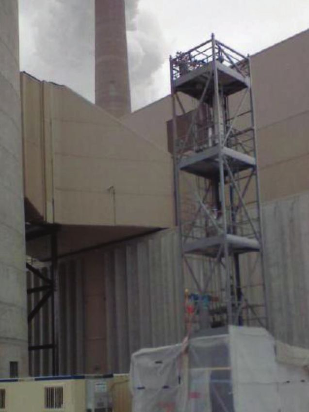
NATIONAL ENERGY TECHNOLOGY LABORATORY
LIST OF TABLES
Table of Contents
Table 1-1. Issues/Barriers and Mitigation Strategies.................... . . . . . . . . . . . . . . . . . . . . . . . . . . . . . . . . . . . . . . . . . . . . . . . . . . . . . . . . . . . . . . . . . . . . . . . . . . . . . . . . . . . . . . . . . . . . . . . . . . . . . . . . . . . . . . . . 8
Table 2-1. Active CO2 Capture Technology R&D Projects. . .............. . . . . . . . . . . . . . . . . . . . . . . . . . . . . . . . . . . . . . . . . . . . . . . . . . . . . . . . . . . . . . . . . . . . . . . . . . . . . . . . . . . . . . . . . . . . . . . . . . . . . . . . . . . . . . . . 13
Table 3-1. Market-Based R&D Goals for Advanced Coal Power Systems. . . . . . . . . . . . . . . . . . . . . . . . . . . . . . . . . . . . . . . . . . . . . . . . . . . . . . . . . . . . . . . . . . . . . . . . . . . . . . . . . . . . . . . . . . . . . . . . . . . . . . . . . . . . 20
Table 3-2. Carbon Capture Program Goals. ............................... . . . . . . . . . . . . . . . . . . . . . . . . . . . . . . . . . . . . . . . . . . . . . . . . . . . . . . . . . . . . . . . . . . . . . . . . . . . . . . . . . . . . . . . . . . . . . . . . . . . . . . . . . . . . . . . 24
Table 4-1. Post-Combustion Technology Advantages and Challenges.. . . . . . . . . . . . . . . . . . . . . . . . . . . . . . . . . . . . . . . . . . . . . . . . . . . . . . . . . . . . . . . . . . . . . . . . . . . . . . . . . . . . . . . . . . . . . . . . . . . . . .. . . . . . . 30
Table 4-2. Pre-Combustion Technology Advantages and Challenges.. . . . . . . . . . . . . . . . . . . . . . . . . . . . . . . . . . . . . . . . . . . . . . . . . . . . . . . . . . . . . . . . . . . . . . . . . . . . . . . . . . . . . . . . . . . . . . . . . . . . . . . . . . . . . . 36
Table A-1. Definitions of Technology Readiness Levels. ................ . . . . . . . . . . . . . . . . . . . . . . . . . . . . . . . . . . . . . . . . . . . . . . . . . . . . . . . . . . . . . . . . . . . . . . . . . . . . . . . . . . . . . . . . . . . . . . . . . . . . . . . .. . . . . . . 45
Table B-1. Post-Combustion Capture Projects............................ . . . . . . . . . . . . . . . . . . . . . . . . . . . . . . . . . . . . . . . . . . . . . . . . . . . . . . . . . . . . . . . . . . . . . . . . . . . . . . . . . . . . . . . . . . . . . . . . . . . . . . . . . . . . . . . 47
Table B-2. Pre-Combustion Capture Projects............................. . . . . . . . . . . . . . . . . . . . . . . . . . . . . . . . . . . . . . . . . . . . . . . . . . . . . . . . . . . . . . . . . . . . . . . . . . . . . . . . . . . . . . . . . . . . . . . . . . . . . . . . . . . . . . . . 50
LIST OF FIGURES
Figure 1-1. CCS and Power Systems Subprograms. . ..................... . . . . . . . . . . . . . . . . . . . . . . . . . . . . . . . . . . . . . . . . . . . . . . . . . . . . . . . . . . . . . . . . . . . . . . . . . . . . . . . . . . . . . . . . . . . . . . . . . . . . . . . .. . . . . . . . 4
Figure 1-2. Carbon Capture Program Technology Areas................ . . . . . . . . . . . . . . . . . . . . . . . . . . . . . . . . . . . . . . . . . . . . . . . . . . . . . . . . . . . . . . . . . . . . . . . . . . . . . . . . . . . . . . . . . . . . . . . . . . . . . . . . . . . . . . . . 5
Figure 1-3. CCS Technology Category Definitions........................ . . . . . . . . . . . . . . . . . . . . . . . . . . . . . . . . . . . . . . . . . . . . . . . . . . . . . . . . . . . . . . . . . . . . . . . . . . . . . . . . . . . . . . . . . . . . . . . . . . . . . . . . . . . . . . . . 6
Figure 1-4. Technology Readiness Level—Relationship to Scale, Degree of Integration, and Test Environment. . . . . . . . . . . . . . . . . . . . . . . . . . . . . . . . . . . . . . . . . . . . . . . . . . .. . . . . . . . 7
Figure 1-5. Summary of Characteristics at Different Development Scales. . . . . . . . . . . . . . . . . . . . . . . . . . . . . . . . . . . . . . . . . . . . . . . . . . . . . . . . . . . . . . . . . . . . . . . . . . . . . . . . . . . . . . . . . . . . . . . . . .. . . . . . . . 8
Figure 2-1. Technology Areas and Key Technologies for Carbon Capture Program. . . . . . . . . . . . . . . . . . . . . . . . . . . . . . . . . . . . . . . . . . . . . . . . . . . . . . . . . . . . . . . . . . . . . . . . . . . . . . . . . . . . . . . .. . . . . . . 11
Figure 2-2. Block Diagram Illustrating Power Plant with Post-Combustion CO2 Capture.. . . . . . . . . . . . . . . . . . . . . . . . . . . . . . . . . . . . . . . . . . . . . . . . . . . . . . . . . . . . . . . . . . . . . . . . . . . . . . . .. . . . . . . 12
Figure 2-3. Block Diagram Illustrating Power Plant with Pre-Combustion CO2 Capture.. . . . . . . . . . . . . . . . . . . . . . . . . . . . . . . . . . . . . . . . . . . . . . . . . . . . . . . . . . . . . . . . . . . . . . . . . . . . . . . . . . . . . . . . 13
Figure 2-4. Components of CO2 Capture Technology Development. . . . . . . . . . . . . . . . . . . . . . . . . . . . . . . . . . . . . . . . . . . . . . . . . . . . . . . . . . . . . . . . . . . . . . . . . . . . . . . . . . . . . . . . . . . . . . . . . . . . . . . . . .. . . . . . . 14
Figure 2-5. CO2 Capture Technology RD&D Funnel. ..................... . . . . . . . . . . . . . . . . . . . . . . . . . . . . . . . . . . . . . . . . . . . . . . . . . . . . . . . . . . . . . . . . . . . . . . . . . . . . . . . . . . . . . . . . . . . . . . . . . . . . . . . . . . . . . . . 16
Figure 3-1. Targets for Technology Contributions to Overall CCRP Cost of Capture Goals—IGCC Pathway. . . . . . . . . . . . . . . . . . . . . . . . . . . . . . . . . . . . . . . . . . . . . . . . . . . . . . . . . . .. . . . . . . 21
Figure 3-2. Targets for Technology Contributions to Overall CCRP Cost of Capture Goals—Post-Combustion New Plants Pathway. . . . . . . . . . . . . . . . . . . . . . . . . . . .. . . . . . . 22
Figure 3-3. Goals for Post-Combustion Retrofits. ....................... . . . . . . . . . . . . . . . . . . . . . . . . . . . . . . . . . . . . . . . . . . . . . . . . . . . . . . . . . . . . . . . . . . . . . . . . . . . . . . . . . . . . . . . . . . . . . . . . . . . . . . . . . . . . . . . 23
Figure 4-1. Process Schematic of Post-Combustion Capture. ......... . . . . . . . . . . . . . . . . . . . . . . . . . . . . . . . . . . . . . . . . . . . . . . . . . . . . . . . . . . . . . . . . . . . . . . . . . . . . . . . . . . . . . . . . . . . . . . . . . . . . . . . .. . . . . . . 27
Figure 4-2. Key Technologies and Associated Research Focus for Post-Combustion Capture. . . . . . . . . . . . . . . . . . . . . . . . . . . . . . . . . . . . . . . . . . . . . . . . . . . . . . . . . . . . . . . . . . . . . . . . . . .. . . . . . . 28
Figure 4-3. Post-Combustion Capture Development Timeline. ....... . . . . . . . . . . . . . . . . . . . . . . . . . . . . . . . . . . . . . . . . . . . . . . . . . . . . . . . . . . . . . . . . . . . . . . . . . . . . . . . . . . . . . . . . . . . . . . . . . . . . . . . .. . . . . . . 32
Figure 4-4. Process Schematic of Pre-Combustion Capture. .......... . . . . . . . . . . . . . . . . . . . . . . . . . . . . . . . . . . . . . . . . . . . . . . . . . . . . . . . . . . . . . . . . . . . . . . . . . . . . . . . . . . . . . . . . . . . . . . . . . . . . . . . .. . . . . . . 33
Figure 4-5. Key Technologies and Associated Research Focus for Pre-Combustion Capture.. . . . . . . . . . . . . . . . . . . . . . . . . . . . . . . . . . . . . . . . . . . . . . . . . . . . . . . . . . . . . . . . . . . . . . . . . . . . . . . . . . . 34
Figure 4-6. Pre-Combustion Capture Development Timeline. . ....... . . . . . . . . . . . . . . . . . . . . . . . . . . . . . . . . . . . . . . . . . . . . . . . . . . . . . . . . . . . . . . . . . . . . . . . . . . . . . . . . . . . . . . . . . . . . . . . . . . . . . . . . . . . . . . . 37
Figure 5-1. NCCC Post-Combustion Capture Test Facility. .............. . . . . . . . . . . . . . . . . . . . . . . . . . . . . . . . . . . . . . . . . . . . . . . . . . . . . . . . . . . . . . . . . . . . . . . . . . . . . . . . . . . . . . . . . . . . . . . . . . . . . . . . .. . . . . . . 39
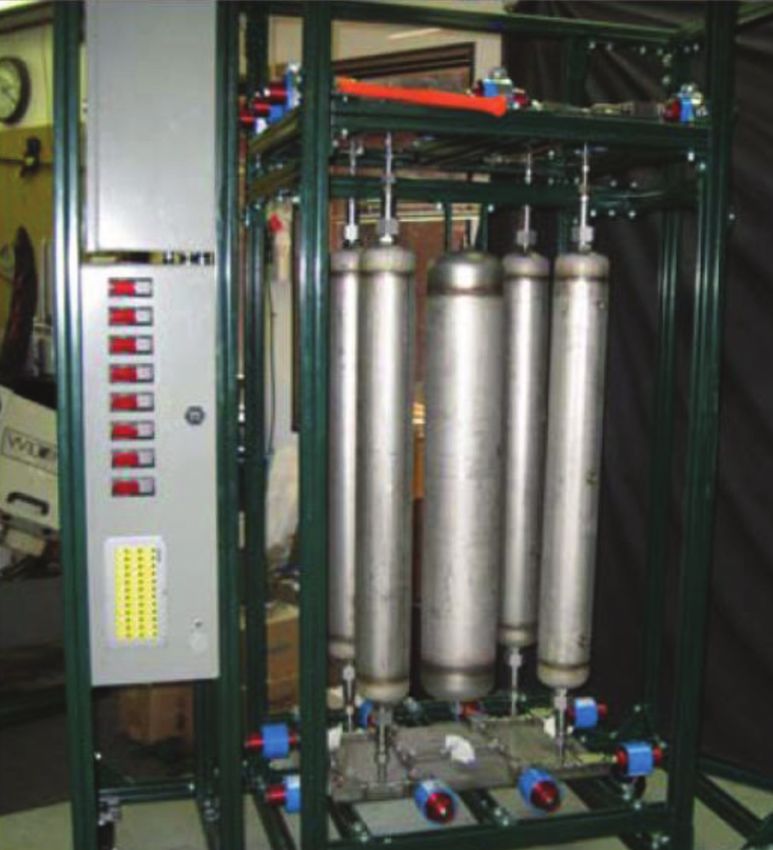
Figure 5-2. NCCC Pre-Combustion Capture Test Facility. ............... . . . . . . . . . . . . . . . . . . . . . . . . . . . . . . . . . . . . . . . . . . . . . . . . . . . . . . . . . . . . . . . . . . . . . . . . . . . . . . . . . . . . . . . . . . . . . . . . . . . . . . . .. . . . . . . 40
Figure 5-3. Carbon Capture Program RD&D Roadmap.................. . . . . . . . . . . . . . . . . . . . . . . . . . . . . . . . . . . . . . . . . . . . . . . . . . . . . . . . . . . . . . . . . . . . . . . . . . . . . . . . . . . . . . . . . . . . . . . . . . . . . . . . . . . . . . . . 41
v
CARBON CAPTURE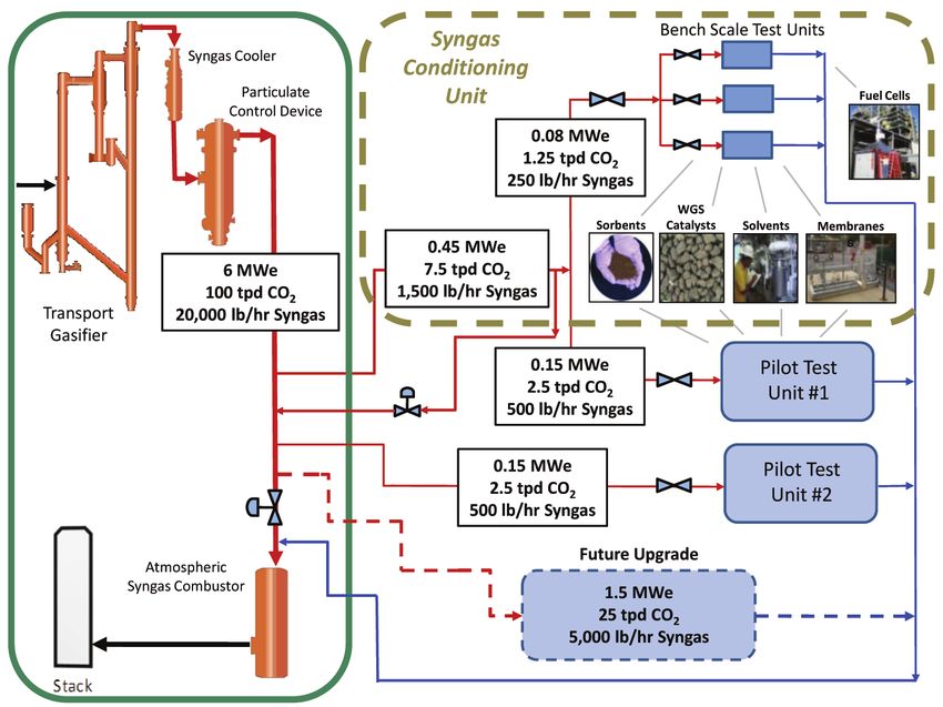
U.S. DEPARTMENT OF ENERGY
Chapter 1: Overview

                                                  CHAPTER 1:   OVERVIEW

          2
                      TECHNOLOGY PROGRAM PLAN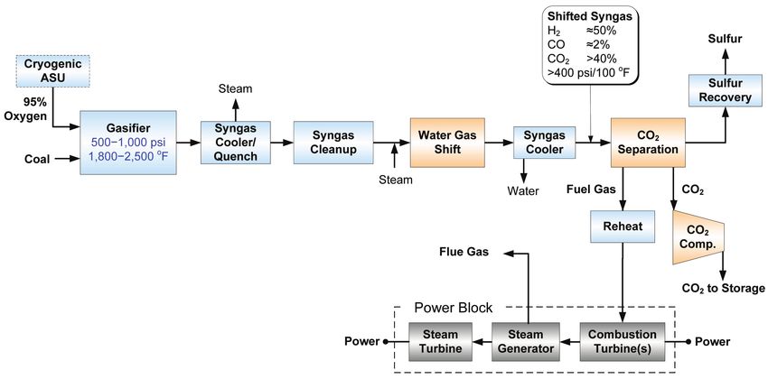
NATIONAL ENERGY TECHNOLOGY LABORATORY

1.1 INTRODUCTION

                                                                                                                        Chapter 1: Overview
The Department of Energy’s (DOE) Carbon Capture program is conducted under the Clean Coal Research Program
(CCRP). DOE’s overarching mission is to increase the energy independence of the United States and to advance
U.S. national and economic security. To that end, the DOE Office of Fossil Energy (FE) has been charged with
ensuring the availability of ultraclean (near-zero emissions), abundant, low-cost domestic energy from coal to fuel
economic prosperity, strengthen energy independence, and enhance environmental quality. As a component of that
effort, the CCRP—administered by the Office of Clean Coal and implemented by the National Energy Technology
Laboratory (NETL)—is engaged in research, development, and demonstration (RD&D) activities to create tech-
nology and technology-based policy options for public benefit. The CCRP is designed to remove environmental
concerns related to coal use by developing a portfolio of innovative technologies, including those for carbon capture
and storage (CCS). The CCRP comprises two major program areas: CCS and Power Systems and CCS Demon-
strations. The CCS and Power Systems program area is described in more detail below. The CCS Demonstrations
program area includes three key subprograms: Clean Coal Power Initiative, FutureGen 2.0, and Industrial Carbon
Capture and Storage. The technology advancements resulting from the CCS and Power Systems program area are
complemented by the CCS Demonstrations program area, which provides a platform to demonstrate advanced coal-
based power generation and industrial technologies at commercial scale through cost-shared partnerships between
the Government and industry.

While it has always been an influential component of CCS research, recently DOE has increased its focus on carbon
utilization to reflect the growing importance of developing beneficial uses for carbon dioxide (CO2). At this time,
the most significant utilization opportunity for CO2 is in enhanced oil recovery (EOR) operations. The CO2 captured
from power plants or other large industrial facilities can be injected into existing oil reservoirs. The injected CO2
helps to dramatically increase the productivity of previously depleted wells—creating jobs, reducing America’s for-
eign oil imports, and thus increasing energy independence. Simultaneously, the CO2 generated from power produc-
tion is stored permanently and safely. The CCRP is gathering the data, building the knowledge base, and developing
the advanced technology platforms needed to prove that CCS can be a viable strategy for reducing greenhouse gas
(GHG) emissions to the atmosphere, thus ensuring that coal remains available to power a sustainable economy.
Program efforts have positioned the United States as the global leader in clean coal technologies.

This document serves as a program plan for NETL’s Carbon Capture research and development (R&D) effort,
which is conducted under the CCRP’s CCS and Power Systems program area. The program plan describes the Car-
bon Capture R&D efforts in 2013 and beyond. Program planning is a strategic process that helps an organization
envision the future; build on known needs and capabilities; create a shared understanding of program challenges,
risks, and potential benefits; and develop strategies to overcome the challenges and risks, and realize the benefits.
The result of this process is a technology program plan that identifies performance targets, milestones for meeting
these targets, and a technology pathway to optimize R&D activities. The relationship of the Carbon Capture pro-
gram to the CCS and Power Systems program area is described in the next section.

                                                                                                                          3
                                                                                                      CARBON CAPTURE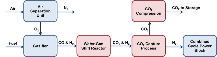
U.S. DEPARTMENT OF ENERGY

                         1.2 CCS AND POWER SYSTEMS PROGRAM AREA
Chapter 1: Overview

                         The CCS and Power Systems program area conducts and supports long-term, high-risk R&D to significantly reduce
                         fossil fuel power-plant emissions (including CO2) and substantially improve efficiency, leading to viable, near-
                         zero-emissions fossil fuel energy systems. The success of NETL research and related program activities will enable
                         CCS technologies to overcome economic, social, and technical challenges including cost-effective CO2 capture,
                         compression, transport, and storage through successful CCS integration with power-generation systems; effective
                         CO2 monitoring and verification; permanence of underground CO2 storage; and public acceptance. The overall pro-
                         gram consists of four subprograms: Advanced Energy Systems, Carbon Capture, Carbon Storage, and Crosscutting
                         Research (Figure 1-1). These four subprograms are further divided into numerous Technology Areas. In several
                         instances, the individual Technology Areas are further subdivided into key technologies.

                                                 ADVANCED ENERGY
                                                 SYSTEMS
                                                 Gasification Systems
                                                                                                    Reduced Cost of Electricity
                                                 Advanced Combustion Systems
                                                 Advanced Turbines
                                                 Solid Oxide Fuel Cells

                                                 CARBON CAPTURE
                                                 Pre-Combustion Capture
                                                                                                    Reduced Cost of Capturing CO2
                                                 Post-Combustion Capture

                                                 CARBON STORAGE
                                                 Regional Carbon Sequestration Partnerships
                                                 Geological Storage
                                                                                                    Safe Storage and Use of CO2
                                                 Monitoring, Verification, Accounting,
                                                 and Assessment
                                                 Focus Area for Carbon Sequestration Science
                                                 Carbon Use and Reuse

                                            CROSSCUTTING
                                            RESEARCH                                            Fundamental Research to
                                            Plant Optimization                                  Support Entire Program
                                            Coal Utilization Sciences
                                            University Training and Research

                                                                    Figure 1-1. CCS and Power Systems Subprograms

          4
                      TECHNOLOGY PROGRAM PLAN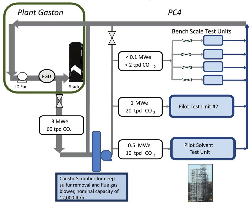
NATIONAL ENERGY TECHNOLOGY LABORATORY

The Advanced Energy Systems subprogram is developing a new generation of clean fossil fuel-
based power systems capable of producing affordable electric power while significantly reducing

                                                                                                                      Chapter 1: Overview
CO2 emissions. This new generation of technologies will essentially be able to overcome potential
environmental barriers and meet any projected environmental emission standards. A key aspect
of the Advanced Energy Systems subprogram is targeted at improving overall thermal efficiency,
including the capture system, which will be reflected in affordable CO2 capture and reduced cost of
electricity (COE). The Advanced Energy Systems subprogram consists of four Technology Areas
as described below:

  -- Gasification Systems research to convert coal
     into clean high-hydrogen synthesis gas (syn-
     gas) that can in-turn be converted into electric-            CARBON CAPTURE
     ity with over 90 percent CCS.                                   PROGRAM
  -- Advanced Combustion Systems research that is
     focused on new high-temperature materials and
                                                                         TECHNOLOGY AREAS
                                                                             Core R&D Research
     the continued development of oxy-combustion
     technologies.
  -- Advanced Turbines research, focused on de-                     POST-COMBUSTION CAPTURE
     veloping advanced technology for the integral
     electricity-generating component for both gasi-
     fication and advanced combustion-based clean
     energy plants fueled with coal by providing ad-                PRE-COMBUSTION CAPTURE
     vanced hydrogen-fueled turbines, supercritical
     CO2-based power cycles and advanced steam
     turbines.
  -- Solid Oxide Fuel Cells research is focused on         Figure 1-2. Carbon Capture Program Technology Areas
     developing low-cost, highly efficient solid ox-
     ide fuel cell power systems that are capable of simultaneously producing electric power
     from coal with carbon capture when integrated with coal gasification.
The Carbon Capture subprogram is focused on the development of post-combustion and pre-com-
bustion CO2 capture technologies for new and existing power plants (Figure 1-2). Post-combustion
CO2 capture technology is applicable to conventional combustion-based power plants, while pre-
combustion CO2 capture is applicable to gasification-based systems. In both cases, R&D is under-
way to develop solvent-, sorbent-, and membrane-based capture technologies.

The Carbon Storage subprogram advances safe, cost-effective, permanent geologic storage of
CO2. The technologies developed and large-volume injection tests conducted through this subpro-
gram will be used to benefit the existing and future fleet of fossil fuel power-generating facilities by
developing tools to increase our understanding of geologic reservoirs appropriate for CO2 storage
and the behavior of CO2 in the subsurface.

The Crosscutting Research subprogram serves as a bridge between basic and applied research by
fostering the R&D of instrumentation, sensors, and controls targeted at enhancing the availability
and reducing the costs of advanced power systems. This subprogram also develops computation,
simulation, and modeling tools focused on optimizing plant design and shortening developmental
timelines, as well as other crosscutting issues, including plant optimization technologies, environ-
mental and technical/economic analyses, coal technology export, and integrated program support.

                                                                                                                        5
                                                                                                     CARBON CAPTURE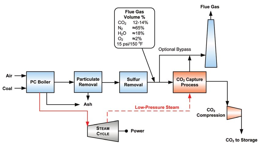
U.S. DEPARTMENT OF ENERGY

                         The CCS and Power Systems program area is pursuing three categories of CCS and related technologies referred to
                         as 1st-Generation, 2nd-Generation, and Transformational. These categories are defined in Figure 1-3.
Chapter 1: Overview

                                       1st-Generation Technologies—include technology components that are being demonstrated or that are
                                       commercially available.

                                       2nd-Generation Technologies—include technology components currently in R&D that will be ready for
                                       demonstration in the 2020–2025 timeframe.

                                       Transformational Technologies—include technology components that are in the early stage of development or
                                       are conceptual that offer the potential for improvements in cost and performance beyond those expected from 2nd-
                                       Generation technologies. The development and scaleup of these “Transformational” technologies are expected to occur
                                       in the 2016–2030 timeframe, and demonstration projects are expected to be initiated in the 2030–2035 time period.

                                                                             Figure 1-3. CCS Technology Category Definitions

                         1.3 THE RD&D PROCESS
                         The research, development, and demonstration of advanced fossil fuel power-generation technologies follows a
                         sequential progression of steps toward making the technology available for commercial deployment, from early
                         analytic study through pre-commercial demonstration. Planning the RD&D includes estimating when funding op-
                         portunity announcements (FOAs) will be required, assessing the progress of ongoing projects, and estimating the
                         costs to determine budget requirements.

                         1.3.1 TECHNOLOGY READINESS LEVELS
                         The Technology Readiness Level (TRL) concept was adopted by the National Aeronautics and Space Administra-
                         tion (NASA) to help guide the RD&D process. TRLs provide an assessment of technology development progress on
                         the path to meet the final performance specifications. The typical technology development process spans multiple
                         years and incrementally increases scale and system integration until final-scale testing is successfully completed.
                         The TRL methodology is defined as a “systematic metric/measurement system that supports assessments of the ma-
                         turity of a particular technology and the consistent comparison of maturity between different types of technology.”1
                         Appendix A includes a table of TRLs as defined by DOE’s Office of Fossil Energy.

                         The TRL score for a technology is established based upon the scale, degree of system integration, and test environ-
                         ment in which the technology has been successfully demonstrated. Figure 1-4 provides a schematic outlining the
                         relationship of those characteristics to the nine TRLs.

                         1     Mankins, J., Technology Readiness Level White Paper, 1995, rev. 2004, Accessed September 2010.
                               http://www.artemisinnovation.com/images/TRL_White_Paper_2004-Edited.pdf

          6
                      TECHNOLOGY PROGRAM PLAN
NATIONAL ENERGY TECHNOLOGY LABORATORY
RESEARCH, DEVELOPMENT, AND DEMONSTRATION
Chapter 1: Overview
TECHNOLOGY DEVELOPMENT DEMONSTRATION
COMMERCIAL DEPLOYMENT
TECHNOLOGY
SCALE
Concepts Lab/Bench Scale Pilot Scale Pre-Commercial Full Scale
INTEGRATION
SYSTEM
Paper Study Component Level Prototype System Full Plant
ENVIRONMENT
Simulated Actual Operational
TEST
TRL 1 TRL 2 TRL 3 TRL 4 TRL 5 TRL 6 TRL 7 TRL 8 TRL 9
Figure 1-4. Technology Readiness Level—Relationship to Scale, Degree of Integration, and Test Environment
The scale of a technology is the size of the system relative to the final scale of the application, which in this case is a
full-scale commercial power-production facility. As RD&D progresses, the scale of the tests increases incremental-
ly from lab/bench scale, to pilot scale, to pre-commercial scale, to full-commercial scale. The degree of system inte-
gration considers the scope of the technology under development within a particular research effort. Early research
is performed on components of the final system, a prototype system integrates multiple components for testing, and
a demonstration test of the technology is fully integrated into a plant environment. The test environment considers
the nature of the inputs and outputs to any component or system under development. At small scales in a labora-
tory setting it is necessary to be able to simulate a relevant test environment by using simulated heat and materials
streams, such as simulated flue gas or electric heaters. As RD&D progresses in scale and system integration, it is
necessary to move from simulated inputs and outputs to the actual environment (e.g., actual flue gas, actual syngas,
and actual heat integration) to validate the technology. At full scale and full plant integration, the test environment
must also include the full range of operational conditions (e.g., startup and turndown).
1.3.2 RD&D RISK AND COST PROGRESSION
As the test scale increases, the duration and cost of the projects increase, but the probability of technical success
also tends to increase. Given the high technical risk at smaller scales, there will often be several similar projects that
are simultaneously supported by the program. On the other hand, due to cost considerations, the largest projects are
typically limited to one or two that are best-in-class. Figure 1-5 provides an overview of the scope of laboratory/
bench-, pilot-, and demonstration-scale testing in terms of test length, cost, risk, and test conditions. In the TRL
construct, “applied research” is considered to be equivalent to lab/bench-scale testing, “development” is carried out
via pilot-scale field testing, and “large-scale testing” is the equivalent of demonstration-scale testing. The CCS and
Power Systems program area encompasses the lab/bench-scale and pilot-scale field testing stages and readies the
technologies for demonstration-scale testing.
7
CARBON CAPTUREU.S. DEPARTMENT OF ENERGY
Progress Over Time
Chapter 1: Overview
RESEARCH, DEVELOPMENT, AND DEMONSTRATION
TRL 2–4 TRL 5–6 TRL 7–9
Lab/Bench-Scale Testing Pilot-Scale Field Testing Demonstration-Scale Testing
Short duration tests (hours/days) Longer duration (weeks/months) Extended duration (typically years)
Low to moderate cost Higher cost Major cost
Medium to high risk of failure Low to medium risk of failure Minimal risk of failure
Artificial and simulated Controlled operating conditions Variable operating conditions
operating conditions
Evaluation of performance and cost Demonstration at full-scale
Proof-of-concept and of technology in parametric tests commercial application
parametric testing to set up demonstration projects
Figure 1-5. Summary of Characteristics at Different Development Scales
1.4 BARRIERS/RISKS AND MITIGATION STRATEGIES
The risk and mitigation strategy to achieving all performance targets by 2030 is summarized in Table 1-1. The over-
arching challenge to be addressed by Carbon Capture is to economically generate clean energy using fossil fuels.
The same barriers, risks, and mitigation strategies apply to all Technology Areas.
Table 1-1. Issues/Barriers and Mitigation Strategies
Issue Barrier/Risk Mitigation Strategy
Cost: Economically generating clean energy Existing/new plants do not adopt advanced Near-, mid-, and long-term R&D projects to
using fossil fuels Carbon Capture technologies foster the commercialization of advanced
technologies
Performance: Achieve performance targets by Lower natural gas prices
2030 Comprehensive, multipronged R&D approach to
Reduced Carbon Capture program budget advanced CO2 capture technologies
Environment: Meet near-zero emissions
(including >90% CO2 capture) with minimal
cost impact
Market: Low economic growth; natural gas price
Regulations: Uncertainties
8
TECHNOLOGY PROGRAM PLANNATIONAL ENERGY TECHNOLOGY LABORATORY
THIS PAGE INTENTIONALLY LEFT BLANK
Chapter 1: Overview
9
CARBON CAPTUREU.S. DEPARTMENT OF ENERGY
Chapter 2: Carbon Capture Program
CHAPTER 2: CARBON CAPTURE PROGRAM
10
TECHNOLOGY PROGRAM PLANNATIONAL ENERGY TECHNOLOGY LABORATORY
2.1 INTRODUCTION
Chapter 2: Carbon Capture Program
The Carbon Capture program consists of two core research Technology Areas: (1) Post-Combustion Capture and
(2) Pre-Combustion Capture. Post-combustion capture is primarily applicable to conventional pulverized coal (PC)-
fired power plants, where the fuel is burned with air in a boiler to produce steam that drives a turbine/generator to
produce electricity. The carbon is captured from the flue gas after fuel combustion. Pre-combustion capture is ap-
plicable to integrated gasification combined cycle (IGCC) power plants, where solid fuel is converted into gaseous
components (syngas) by applying heat under pressure in the presence of steam and oxygen. In this case, the carbon
is captured from the syngas before combustion and power production occurs. Although R&D efforts are focused on
capturing CO2 from the flue gas or syngas of coal-based power plants, the same capture technologies are applicable
to natural gas- and oil-fired power plants and other industrial CO2 sources.
Current R&D efforts conducted within the Carbon Capture program include development of advanced solvents,
sorbents, and membranes for both the Post- and Pre-Combustion Technology Areas (Figure 2-1). The research
focus for these post-combustion and pre-combustion technologies is presented in Chapter 4. Under both Technol-
ogy Areas, the program is developing 2nd-Generation and Transformational CO2 capture technologies that have the
potential to provide step-change reductions in both cost and energy penalty as compared to currently available 1st-
Generation technologies. The success of the program in developing these technologies will enable cost-effective
implementation of CCS throughout the power-generation sector and ensure that the United States will continue to
have access to safe, reliable, and affordable energy from fossil fuels.
CARBON CAPTURE
TECHNOLOGY AREAS KEY TECHNOLOGIES
Solvents
POST-COMBUSTION CAPTURE
Sorbents
PRE-COMBUSTION CAPTURE
Membranes
Figure 2-1. Technology Areas and Key Technologies for Carbon Capture Program
2.2 BACKGROUND
CCS begins with the separation and capture of CO2 from coal-based power plant flue gas or syngas. There are
commercially available 1st-Generation CO2 capture technologies that are currently being used in various industrial
applications. However, in their current state of development these technologies are not ready for implementation on
coal-based power plants because they have not been demonstrated at appropriate scale, require approximately one-
third of the plant’s steam and power to operate, and are very expensive. For example, DOE/NETL estimates that
the deployment of a current 1st-Generation post-combustion CO2 capture technology—chemical absorption with an
11
CARBON CAPTUREU.S. DEPARTMENT OF ENERGY
aqueous monoethanolamine solution—on a new PC power plant would increase the COE by ≈80 percent and derate
the plant’s net generating capacity by as much as 30 percent. Other major challenges include energy integration, flue
Chapter 2: Carbon Capture Program
gas contaminants, water use, CO2 compression, and oxygen supply for pre-combustion systems.
The net electrical output from a coal-based power plant employing currently available 1st-Generation CO2 capture
and compression technologies will be significantly less than that for the same plant without capture. This is because
some of the energy—thermal and electrical—produced at the plant must be used to operate the CO2 capture and
compression processes. Steam usage decreases the gross electrical generation, while the additional auxiliary power
usage decreases the net electrical output of the power plant. Implementation of CO2 capture results in a 7–10 per-
centage point decrease in net plant efficiency depending on the type of power-generation facility.
The energy penalty associated with CO2 capture has been estimated in a DOE study conducted to determine the cost
and performance of a post-combustion CO2 capture technology retrofit on American Electric Power’s coal-fired
Conesville Unit No. 5. The amine-based CO2 capture process would require extraction of approximately 50 percent
of the steam that normally flows through the low-pressure turbine for a 90 percent CO2 capture scenario. Conse-
quently, the gross power output of the unit would decrease by ≈16 percent (from 463.5 MWe to 388.0 MWe). In
addition, the auxiliary power requirements for the CO2 capture and compression system would be 55 MWe. The
combined effect of steam and auxiliary power required to operate the CO2 capture and compression system is a
reduction in the net power output of the unit by approximately 30 percent (from 433.8 MWe to 303.3 MWe).
Post-combustion CO2 capture is primarily applicable to conventional coal-, oil-, or gas-fired power plants, but could
also be applicable to IGCC and natural gas combined cycle flue gas capture. A simplified block diagram illustrating
the post-combustion CO2 capture process is shown in Figure 2-2. In a typical coal-fired power plant, fuel is burned
with air in a boiler to produce steam that drives a turbine/generator to produce electricity. Flue gas from the boiler
consists mostly of nitrogen (N2) and CO2. The CO2 capture process would be located downstream of the conven-
tional pollutant controls for nitrogen oxides (NOx), particulate matter (PM), and sulfur dioxide (SO2). Chemical
solvent-based technologies currently used in industrial applications are being considered for this purpose. The
chemical solvent process requires the extraction of a relatively large volume of low-pressure steam from the power
plant’s steam cycle, which decreases the gross electrical generation of the plant. The steam is required for release of
the captured CO2 and regeneration of the solvent. Separating CO2 from this flue gas is challenging for several rea-
sons: a high volume of gas must be treated (≈2 million cubic feet per minute for a 550-MWe plant), the CO2 is dilute
(between 12 and 14 percent CO2), the flue gas is at atmospheric pressure, trace impurities (PM, SO2, NOx, etc.) can
degrade capture media, and compressing captured CO2 from near-atmospheric pressure to pipeline pressure (about
2,200 pounds per square inch absolute [psia]) requires a large auxiliary power load.
Figure 2-2. Block Diagram Illustrating Power Plant with Post-Combustion CO2 Capture
Pre-combustion capture is mainly applicable to gasification plants, where fuel (coal, biomass, or coal/biomass mix-
ture) is converted into gaseous components by applying heat under pressure in the presence of steam and sub-stoi-
chiometric oxygen (O2). A simplified block diagram illustrating the pre-combustion CO2 capture process is shown in
Figure 2-3. By carefully controlling the amount of O2, only a portion of the fuel burns to provide the heat necessary
to decompose the fuel and produce syngas, a mixture of hydrogen (H2) and carbon monoxide, and minor amounts
of other gaseous constituents. To enable pre-combustion capture, the syngas is further processed in a water-gas-
12
TECHNOLOGY PROGRAM PLANNATIONAL ENERGY TECHNOLOGY LABORATORY
shift (WGS) reactor, which converts carbon monoxide into CO2 while producing additional H2, thus increasing the
CO2 and H2 concentrations. An acid-gas-removal system can then be used to separate the CO2 from the H2. Physical
Chapter 2: Carbon Capture Program
solvent-based technologies currently used in industrial applications are being considered for this purpose. After CO2
removal, the H2-rich syngas is used as a fuel in a combustion turbine combined cycle to generate electricity.
Figure 2-3. Block Diagram Illustrating Power Plant with Pre-Combustion CO2 Capture
2.3 RECENT R&D ACTIVITIES
Current R&D efforts conducted within the Carbon Capture program are focused on development of advanced sol-
vents, sorbents, and membranes for both the Post-Combustion and Pre-Combustion Technology Areas. Research
projects are carried out using various funding mechanisms—including partnerships, cooperative agreements, and
financial assistance grants—with corporations, small businesses, universities, nonprofit organizations, and other
national laboratories and Government agencies. Current efforts cover the development of 2nd-Generation and Trans-
formational CO2 capture technologies. Although the majority of these technologies are still in the laboratory- and
bench-scale stages of development, a limited number of small pilot-scale field tests have been initiated. Table 2-1
presents the number of active projects per Technology Area and test scale. A complete list of active Carbon Capture
projects is presented in Appendix B.
Table 2-1. Active CO2 Capture Technology R&D Projects
CO2 Capture Technology Pathway Laboratory/Bench-Scale Projects Small Pilot-Scale Projects
Post-Combustion 28 6
Pre-Combustion 8 0
More details on the specific advanced capture technologies currently under development are available in the report
entitled, DOE/NETL Advanced Carbon Dioxide Capture R&D Program: Technology Update, which is available at:
http://www.netl.doe.gov/technologies/coalpower/ewr/pubs/CO2Handbook/
2.4 IMPORTANT ASPECTS OF CARBON CAPTURE PROGRAM R&D PROCESS
The Carbon Capture program comprises a comprehensive effort to develop cost-effective, advanced, post-, and pre-
combustion technologies for power plants and other industrial facilities that significantly reduce the energy penalty
and capital cost compared to currently available 1st-Generation technologies. The RD&D process to develop these
technologies includes several important aspects, including (1) putting together pieces of the technology puzzle, (2)
progress over time, and (3) technology down-selection and scaleup.
2.4.1 PUTTING TOGETHER THE PIECES OF THE PUZZLE
The development of a 2nd-Generation or Transformational CO2 capture technology includes more than laboratory-
scale testing of process chemistry and physics and evaluation of associated operating parameters. The research ef-
fort can also involve the development of new chemical production methods, novel process equipment designs, new
13
CARBON CAPTUREU.S. DEPARTMENT OF ENERGY
equipment manufacturing methods, and opti-
mization of the process integration with other
Chapter 2: Carbon Capture Program
power-plant systems (e.g., the steam cycle,
cooling water system, and CO2 compres-
sion system). Figure 2-4 presents the various
R&D components that might be necessary to
take a capture technology from concept to
commercial reality. Developing a successful
CO2 capture technology requires putting to-
gether all these pieces of the puzzle. While
some of these developments are unique to a
specific process, others could be more gener-
ally applicable. For example, a novel process
equipment design developed by one research
organization could prove vital to optimizing
performance of the process chemistry devel-
oped by another research organization. While
most of the CO2 capture technology projects
encompass the entire range of R&D compo-
nents, there are some that focus more on a
Figure 2-4. Components of CO2 Capture Technology Development
specific component or perhaps are more suc-
cessful with a specific component (e.g., pro-
cess chemistry or process equipment design).
As a result, it could take the integration of the successful development of multiple components from multiple
researchers to eventually arrive at a successful and cost-effective CO2 capture technology. For example, a post-
combustion, solvent-based CO2 capture process might require a synthesis of the following “pieces” to be judged
an overall technology success: (1) an advanced solvent with superior working capacity and regeneration energy re-
quirements, (2) an advanced absorption reactor with improved mass transfer capability, and (3) an advanced regen-
eration reactor/re-boiler that minimizes energy requirements. The successful development of these three separate
technology “pieces” could rely on three separate projects, rather than a single project.
2.4.2 PROGRESS OVER TIME
DOE/NETL envisions having a 2nd-Generation CO2 capture technology portfolio ready for demonstration-scale
testing after 2020 following the sequential progression of laboratory-, bench-, and pilot-scale testing. Similarly, a
Transformational CO2 capture technology portfolio should be ready for demonstration-scale testing after 2030.
As noted previously with regard to the R&D process—generally, there is a relatively high risk of failure associated
with laboratory/bench-scale testing, a lower risk of failure for pilot-scale testing, and a minimal risk of failure for
full-scale demonstrations. Specifically with regard to CO2 capture technology development, laboratory- and bench-
scale testing is usually conducted with simulated flue or synthesis gas at relatively low gas flow rates ranging from
1 to 100 standard cubic feet per minute (scfm). Small pilot-scale testing can also be conducted in a laboratory setting
as a “semi-batch” mode using coal combustors to generate flue gas for process testing. For example, the University
of North Dakota’s Energy and Environmental Research Center (UNDEERC) uses two sizes of combustors for small
pilot-scale testing with equivalent gas flow rates of approximately 10 scfm and 125 scfm.
Upon completion of laboratory- and bench-scale testing, it is necessary to conduct pilot-scale slipstream testing
using actual flue gas to determine potential adverse effects on the process from minor constituents in the coal that
are present in the syngas or combustion flue gas. For example, trace concentrations of arsenic in some coals were
found to poison the catalyst used in the SCR process for control of NOx from coal-fired power plants. Likewise,
14
TECHNOLOGY PROGRAM PLANNATIONAL ENERGY TECHNOLOGY LABORATORY
low concentrations of SO2 are known to degrade amine solvent performance. In addition, potential problems with
excessive scaling, plugging, and/or corrosion of process equipment can be evaluated and solutions developed only
Chapter 2: Carbon Capture Program
via operating experience during long-term, pilot-scale slipstream testing.
The flue gas design flow rates for NETL’s large pilot-scale slipstream testing, including those conducted at the
National Carbon Capture Center (NCCC), will be in the range of 1,000–12,000 scfm. For comparison, a 1-MW gross
electric-generation facility produces approximately 2,500 scfm of combustion flue gas. After successful completion
of pilot-scale testing, the process equipment can be further scaled up to conduct demonstration-scale testing prior to
commercial deployment of the technology.
PROGRESS OVER TIME
An example of the scaleup process is the RD&D being conducted by Membrane Technology and Research, Inc. (MTR) to develop a new
membrane-based post-combustion CO2 capture technology. MTR and NETL initiated the membrane R&D program in 2007. MTR’s first
phase of R&D included bench-scale testing of various membrane designs using a simulated gas flow rate of approximately 2.5 scfm.
Based on successful bench-scale testing, MTR initiated a follow-up project with NETL in 2008 to conduct a small slipstream field test that
was conducted in 2010. The approximately 175-scfm (equivalent to approximately 1 ton per day [tpd] of CO2) testing was conducted at
the Arizona Public Service’s coal-fired Cholla Power Plant located in Arizona. MTR now plans to conduct additional small pilot-scale field
testing based on a gas flow rate of approximately 2,500 scfm (equivalent to approximately 1 MWe or about 20 tpd of CO2) as part of a new
project with NETL that is scheduled for completion in 2015.
15
CARBON CAPTUREU.S. DEPARTMENT OF ENERGY
2.4.3 TECHNOLOGY DOWN-SELECTION AND SCALEUP
Chapter 2: Carbon Capture Program
As described previously, a sequential progression of scaleup testing is necessary to accommodate the RD&D pro-
cess. As shown previously in Figure 1-5, there is a relatively high risk of failure associated with laboratory/bench-
scale testing, a lower risk of failure for pilot-scale testing, and a minimal risk of failure for full-scale demonstrations.
Therefore, in order to ensure a reasonable overall probability of success in eventually developing 2nd-Generation
and Transformational CO2 capture technologies under the program, it is necessary to start with a relatively large
portfolio of laboratory/bench-scale projects. Figure 2-5 presents this concept as an RD&D development “funnel”
that portrays the down-selection and corresponding scaleup process.
Probability of successful outcome relies on large number
of potential options.
LABORATORY/BENCH SCALE
Large number of
potential options
20%
SMALL PILOT SCALE
p
leu
50%
sca
of
el
lev
LARGE PILOT SCALE
ch
ea
th
75%
wi
es
as
cre
DEMONSTRATION
s in
s
cce
75%
su
of
ity
bil
ba
COMMERCIAL
o
Pr
Limited number of = Technology Options
successful outcomes
Figure 2-5. CO2 Capture Technology RD&D Funnel
In this funnel example, a successful outcome for the Carbon Capture R&D program is the development of two
commercially available CO2 capture technologies after a four-step down-selection process that progresses from a
large portfolio of laboratory/bench-scale projects with high risk/low probability of success to a small portfolio of
full-scale demonstration projects with low risk/high probability of success. The progressive down-selection process
accompanying the technology scaleup is necessary because there is no practical means to predict eventual commer-
cial success based on laboratory/bench-scale test results.
16
TECHNOLOGY PROGRAM PLANNATIONAL ENERGY TECHNOLOGY LABORATORY
THIS PAGE INTENTIONALLY LEFT BLANK
Chapter 2: Carbon Capture Program
17
CARBON CAPTUREU.S. DEPARTMENT OF ENERGY
Chapter 3: Goals and Benefits
CHAPTER 3: GOALS AND BENEFITS
18
TECHNOLOGY PROGRAM PLANNATIONAL ENERGY TECHNOLOGY LABORATORY
3.1 GOALS
Chapter 3: Goals and Benefits
The goals of the Carbon Capture program support the energy goals established by the Administration, DOE, FE,
and the CCRP. The priorities, mission, goals, and targets of each of these entities are summarized in Appendix C.
3.1.1 CCRP GOALS
Currently, the CCRP is pursuing the demonstration of 1st-Generation CCS technologies with existing and new
power plants and industrial facilities using a range of capture alternatives and storing CO2 in a variety of geologic
formations. In parallel, to drive down the costs of implementing CCS, the CCRP is pursuing RD&D to decrease the
COE and capture costs and increase base power-plant efficiency, thereby reducing the amount of CO2 that has to be
captured and stored per unit of electricity generated. FE is developing a portfolio of technology options to enable
this country to continue to benefit from using our secure and affordable coal resources. The challenge is to help
position the economy to remain competitive, while reducing carbon emissions.
There are a number of technical and economic challenges that must be overcome before cost-effective CCS tech-
nologies can be implemented. The experience gained from the sponsored demonstration projects focused on state-
of-the-art (1st-Generation) CCS systems and technologies will be a critical step toward advancing the technical,
economic, and environmental performance of 2nd-Generation and Transformational systems and technologies for
future deployment. In addition, the core RD&D projects being pursued by the CCRP leverage public and private
partnerships to support the goal of broad, cost-effective CCS deployment. The following long-term performance
goals for new coal-fired power generation facilities have been established for the CCRP (alternate goals have been
established for retrofit applications, as discussed in the next section):
• Develop 2nd-Generation technologies that:
-- Are ready for demonstration in the 2020–2025 timeframe (with commercial deployment
beginning in 2025)
-- Cost less than $40/tonne of CO2 captured
• Develop Transformational technologies that:
-- Are ready for demonstration in the 2030–2035 timeframe (with commercial deployment
beginning in 2035)
-- Cost less than $10/tonne of CO2 captured
The planning necessary to implement the above goals and targets is well underway and the pace of activities is increas-
ing. The path ahead with respect to advancing CCS technologies, particularly at scale, is very challenging given today’s
economic risk-averse climate and that no regulatory framework is envisioned in the near term for supporting carbon
management. These conditions have caused DOE/FE to explore a strategy with increased focus on carbon utilization as
a means of reducing financial risk. This strategy benefits from FE’s investment in the beneficial utilization of CO2 for
commercial purposes, particularly through the development of next-generation CO2 injection/EOR technology, with
the objective of creating jobs and increasing energy independence. Carbon dioxide injection/EOR is a specific market-
based utilization strategy that will positively impact domestic oil production and economical CO2 capture and storage.
19
CARBON CAPTUREU.S. DEPARTMENT OF ENERGY
3.1.2 CARBON CAPTURE PROGRAM GOALS
Chapter 3: Goals and Benefits
CCRP cost and performance goals, summarized in Table 3-1, can be met by an integrated system if the underly-
ing technology components are successfully developed. The Carbon Capture program supports achievement of
the CCRP goals by developing advanced, efficient carbon capture technologies that produce ultraclean (near-zero
emissions, including CO2), low-cost energy with low water use. In support of those overall goals, specific cost and
performance goals for 2025 and 2035 are described below.
Table 3-1. Market-Based R&D Goals for Advanced Coal Power Systems
Goals (for nth-of-a-kind plants) Performance Combinations that Meet Goals
R&D Portfolio Pathway Cost of Captured CO2, $/tonne 1
COE Reduction 2
Efficiency (HHV) Capital/O&M Reduction3
2nd-Geneneration R&D Goals for Commercial Deployment of Coal Power in 20254
In 2025, EOR revenues will be required for 2nd-Generation coal power to compete with natural gas combined cycle and nuclear in absence of a regulation-based cost for carbon emissions.
Greenfield Advanced Ultra-Supercritical PC 40 20% 37% 13%
with CCS
Greenfield Oxy-Combustion PC with CCS 40 20% 35% 18%
Greenfield Advanced IGCC with CCS ≤40 ≥20% 40% 18%
Retrofit of Existing PC with CCS 45 n/a
Transformational R&D Goals for Commercial Deployment of Coal Power in 20354
Beyond 2035, Transformational R&D and a regulation-based cost for carbon emissions will enable coal power to compete with natural gas combined cycle and nuclear without EOR revenues.
New Plant with CCS—Higher Efficiency PathNATIONAL ENERGY TECHNOLOGY LABORATORY
IGCC PATHWAY – Driving Down the Cost of Capture
Chapter 3: Goals and Benefits
60 Today’s
Coal
$61/tonne Advanced Turbines
Gasification
Advanced
Capture
50 H2 Turbines
Crosscutting Research
Large-Scale Testing
(2,650 °F) Crosscutting Research
Large-Scale Testing
Cost of Capture, 2011 $/tonne CO2
40
WGCU, ITM, 2nd-Generation
Dry, High-Pressure Target Transformational
Feed $40/tonne H2 Turbines
(3,100 °F)
30 Adv. Solvents,
Crosscutting Research
Sorbents, Membranes ITM/Turbine
Large-Scale Testing
Integration
Transformational
20 H2 Production
Transformational
Capture
10
Pulse Combustion Transformational
Target
$10/tonne
0
Today 2025 – 2nd-Generation 2035 – Transformational
Figure 3-1. Targets for Technology Contributions to Overall CCRP Cost of Capture Goals—IGCC Pathway
Establishing program goals for post-combustion capture requires a slightly different approach because the technolo-
gies are applicable to both new plants and existing plant retrofits. For new plants, 2nd-Generation and Transformational
capture cost goals of $40/tonne andYou can also read