CERTIFICATION CLASS LIVE PRESENTATION HANDOUTS 2020 - MNDOT
←
→
Page content transcription
If your browser does not render page correctly, please read the page content below

`

    CERTIFICATION CLASS
     LIVE PRESENTATION
         HANDOUTS
            2020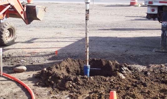
Data Practices Act
Verify roster information, if needed make corrections and Initial
Student will be the one certified thus their data will only be
used for sending cards or other necessary information & upon
other inquiry we will only verify certification status.
“2018 SPEC BOOK”
What's New Since 2015 THE 2018 SPEC BOOK IS NOW THE GOVERNING DOCUMENT ON ALL
MnDOT SIGNAL AND LIGHTING PROJECTS
CHAPTER 2
STANDARD SPECIFICATIONS
AND MANY ITEMS THAT WERE IN THE MnDOT SPECIAL PROVISIONS FOR
SPECIAL PROVISIONS THE 2016 SPEC BOOK HAVE BEEN MOVED TO THE NEW 2018 SPEC
BOOK
“2018 SPEC BOOK” “2018 SPEC BOOK”
THE 2018 SPEC BOOK WRITING STYLE IS
PLAIN LANGUAGE
ACTIVE VOICE/ IMPERATIVE MOOD
COMPLETE, CORRECT, CLEAR, CONCISE, CONSISTANT
THE STANDARD SPECIFICATIONS FOR CONSTRUCTION WILL BE
2565.3 G.1
UPDATED EVERY FIVE YEARS. NEXT UPDATE JUNE 2020
PROVIDE PREFORMED RIGID PVC OR SAW- CUT INDUCTIVE
LOOP DETECTORS AS REQUIRED BY THE CONTRACT.
IN THIS WRITING FORMAT THE CONTRACTOR IS ASSUMED.
1
“WHAT’S NEW SINCE 2015” “WHAT’S NEW SINCE 2015”
2545 & 2565 The 2020 Spec Book 3842 “Electrical Systems Compounds and Lubricants”
Pay Item Extensions clarifies the three very different compounds
2565.5 BASIS OF PAYMENT Anti Seize, No Ox, And Ferrous Metal Electrically Conductive Compound
The Department will pay for new traffic control signal systems on the basis of the following schedule:
Item No: Item: Unit
2565.501 Emergency Vehicle Preemption System lump sum
2565.501 Traffic Control Interconnect lump sum
2565.502 APS Push Button Station each
2565.502 APS Push Button and Sign each
2565.502 APS Cabinet Control Unit each
2565.502 APS Pole Mounting Adaptor each
2565.502 APS Push Button Mounting Spacers each
2565.516 Traffic Control Signal System system
This change in pay item extensions (last 3 digits) was made so all pay items have consistent
extensions with regards to lump sum, each, system, and other extension unit naming.
2-1
CONTRACT DOCUMENTS
CHAPTER 2 PLAN CONTRACT
PROPOSAL
Chapter 4
STANDARD SPECIFICATIONS
AND TRAFFIC CONTROL
FIELD MANUAL
SPECIAL PROVISIONS
STANDARD
PLATES
STANDARD
Chapter 3
SPECIFICATIONS &
Chapter 7
SUPPLEMENTAL
SPECIFICATIONS
2-1 2-2
“ITEMS TO REMEMBER”
PROPOSAL
Addendums
Special Provisions
Division SL - Lighting
Division SS - Signals
Division SZ - TMS
SPEC BOOK
THE STANDARD SPECIFICATIONS (SPEC BOOK) IS A
COLLECTION OF PROVISIONS AND REQUIREMENTS
2545 Lighting
Specifications PERTAINING TO THE PERFORMACE OF WORK
2565 – Signals
Specifications
2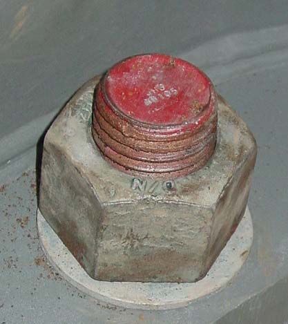
2-2
THE SPEC BOOK IS DIVIDED INTO NUMERIC SERIES BY DIVISION
THREE DIVISIONS:
DIVISION I:
ALL SPECIFICATIONS BEGIN WITH NUMBER 1
(1101 THRU 1911)
DIVISION II:
ALL SPECIFICATIONS BEGIN WITH NUMBER 2
(2021 THRU 2581)
DIVISION I: General Requirements and Covenants DIVISION III:
DIVISION II: Construction Details (2545 & 2565) ALL SPECIFICATIONS BEGIN WITH NUMBER 3
DIVISION III: Materials (3800 Series)
(3101 THRU 3973)
2-2
DIVISION I DIVISION I
GENERAL REQUIREMENTS AND COVENANTS GENERAL REQUIREMENTS AND COVENANTS
DIVISION I
GENERAL REQUIREMENTS AND COVENANT THIS DIVISION IS DIVIDED INTO NINE (9) SECTIONS:
Definitions and Terms
1101 WORDING OF SPECIFICATIONS
Since the 2014 edition, the Minnesota Department of Transportation’s Standard Specification for Construction (Standard Specifications) has (1101-1103) DEFINITIONS AND TERMS
emphasized the active voice. In Division 1, the Contractor’s and Department’s responsibilities are written in the active voice-indicative mood. In a
sentence written in the active voice-indicative mood, someone acts on something. For example: “The Engineer will take a sample.”
(1301-1307) Award and Execution of Contract
(1401-1408) Scope of Work
In Divisions 2 and 3, only the Department’s responsibilities are written in the active voice-indicative mood.
(1201-1313) Bidding Requirements and Conditions
In Divisions 2 and 3, the Contractor’s responsibilities are written in active voice-imperative mood; the Department states its requirements or directions
for performing the work to the Contractor. The imperative mood is used when the party issuing an instruction and the party receiving it are already (1501-1517) CONTROL OF WORK
understood. Such statements have the same force as if they contained the word “shall” and are considered mandatory. In an imperative sentence
such as, “Pour the concrete,” the Department is indicating that it requires the Contractor to pour the concrete. In the material specifications in Division
(1601-1609) Control of Material
3, the subject may also be the supplier, fabricator, or manufacturer supplying the materials, products, or equipment for use on the project. (1701-1721) Legal Relations and Responsibility
to the Public
(1810-1809) Prosecution and Progress
(1901-1911) Measurement and Payment
2-1 2-1
SPECIFICATIONS BOOK
SPECIFICATIONS BOOK MnDOT 1103 – Definition of Terms
MnDOT 1103 – Definition of Terms
DEPARTMENT
The State Department of Transportation, or political subdivision, governmental
body, board, commission, office, department, division, or agency constituted for
ENGINEER
administration of the Contract within its jurisdiction. A Department engineer authorized as the Department’s representative responsible for the
engineering supervision of the work and delegated with those duties and authorities defined in the
contract. The contract may redefine the ‘Engineer’ as a specific Department engineer (i.e.
Concrete Engineer, Bridge Engineer, Materials Engineer, Traffic Engineer, Roadway Engineer, etc.)
with jurisdiction over the engineering details of specific construction items;
3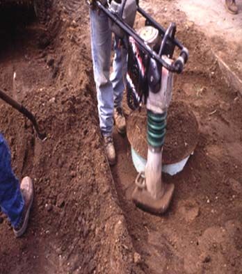
SPECIFICATIONS BOOK
2-1

                                                                                       “SHALL”
              MnDOT 1103 – Definition of Terms

                                                                THE TERM “SHALL” IS NOT USED IN CONTRACT DOCUMENTS
                                                                HOWEVER YOU WILL FIND THIS TERM USED FOR PRODUCT
                                                                SPECIFICATIONS.

                                                                IN THESE DOCUMENTS THE TERM “SHALL” MEANS THAT THE
                                                                ACTION OR CONDITION IS MANDATORY.
                          INSPECTOR
       The Engineer's authorized representative assigned to
           make detailed inspections of Contract work.

2-2                                                             2-2

               SPECIFICATIONS BOOK                                           SPECIFICATIONS BOOK
          DIVISION I – CONTROL OF WORK                                        DIVISION I (Spec 1504)
          Spec 1504 -Coordination of Plans and Specifications            Coordination of Plans and Specifications
                                                                            IN CASE OF DISCREPANCIES:

2-2                                                             2-2

                 DIVISION II                                                SPECIFICATIONS BOOK
                                                                                   DIVISION II
THIS DIVISION IS DIVIDED INTO SIX (6) SECTIONS:                            2565 - Traffic Control Signals

      General (2021 – 2051)                                                               Description
      Grading (2101 – 2118)                                                               Materials
      Base Construction (2201- 2232)                                                      Construction Requirements
      Pavement Construction (2301- 2360)
      Bridges and Structures (2401 – 2481)                                                Method of Measurement
      Miscellaneous (2501 – 2581)                                                         Basis of Payment

                                                                                                                      4
2-2                                                                                           2-3

                                                                                                                 SPECIFICATION BOOK
                     SPECIFICATIONS BOOK                                                                        2545 & 2565 – Traffic Control Signals
                    MnDOT 2565 – Traffic Control Signals                                                         2545.1B QUALIFICATION OF WORKERS

                                      Description
  This section describes the required work and other types of systems governed by these
                                      Specifications.

                                        Materials
                                                                                             Signal and Lighting Certification: When the Contractor is working on Traffic Signal
      This section covers general material specifications such as conduit and accessories    System(s) or Lighting System(s),
                          with references to materials in Division III.                      provide at least one Contractor employee on the site who is MnDOT Signal and
                                                                                             Lighting Certified to perform or directly supervise the installation and testing of any
                                                                                             MnDOT Traffic Signal System or Lighting System.

2-4

                                                                                                              SPECIFICATIONS BOOK
                     SPECIFICATIONS BOOK                                                                          CONSTRUCTION REQUIREMENTS
                       MnDOT 2565 – Traffic Control Signals
                                                                                                                    Installation Requirements 2565.3A.4
                        Construction Requirements                                                                        2545.3A.4 References 2565

           This section specifies the requirements of the actual construction of
                               a traffic control signal system.                                                         A.4 Installation Requirements
                                                                                                           Install materials and devices in accordance with contract
                                                                                                         documents and in accordance with manufacturer‘s installation
                                                                                                                                 requirements.

                                                                                                                   SPECIFICATION BOOK
                                                                                              2-4

                  SPECIFICATIONS BOOK                                                                            MnDOT 2565 – Traffic Control Signals
                       CONSTRUCTION REQUIREMENTS
                     Pole to Concrete Foundation Anchor Rods
                The Standard Specifications for Construction for signals and
            lighting have requirements for tightening the pole to the foundation
                                       anchor rods.
                                                                                                                METHOD OF MEASUREMENT
                                                                                            This section explains how the components of a traffic control signal system will
                                                                                            be measured for payment:
                                                                                            2565.4       METHOD OF MEASUREMENT

                                                                                            THE NEW TRAFFIC CONTROL SIGNAL SYSTEM WILL BE MEASURED AS AN INTEGRAL UNIT
                                                                                            COMPLETE IN PLACE AND OPERATING WITH THE COMPLETE INSTALLATION AT ONE
                                                                                            INTERSECTION CONSIDERED AS ONE UNIT.

                                                                                                                                                                                       5
SPECIFICATION BOOK
2-5

                  SPECIFICATIONS BOOK
                  MnDOT 2565 – Traffic Control Signals                                                           MnDOT 2545 – Lighting Systems
                                                                                                                      METHOD OF MEASUREMENT
                          BASIS OF PAYMENT                                             This section explains how the components of a lighting system will be
                                                                                       measured for payment:
         A new traffic signal system will be paid for on the basis of the following
                                         schedule:                                                                      2545.4 METHOD OF MEASUREMENT
      Item No:                     Item:                    Unit
      2565.516      Traffic Control Signal System                   system                                                             Lighting Units
      2565.502      APS Push Button Station                         each               Engineer will separately measure lighting units of each type of mounting and luminaire design by the number
      2565.502      APS Push Button and Sign                        each               of units of each type, complete in place.
      2565.502      APS Cabinet Control Unit                        each
      2565.502      APS Pole Mounting Adaptor                       each                                                           Direct Buried Lighting Cable
      2565.502      APS Push Button Mounting Spacers                each               Engineer will separately measure direct buried lighting cable of each kind and size by the length between end
      2565.501      Emergency Vehicle Preemption System             lump sum                                      terminals along the centerline of the cable as installed.
      2565.501      Traffic Control Interconnect                    lump sum

                  SPECIFICATIONS BOOK                                                                         SPECIFICATIONS BOOK
                    MnDOT 2545 – Lighting Systems                                                                 MnDOT 2545 – Lighting Systems

                       BASIS OF PAYMENT                                                                                  BASIS OF PAYMENT

                                                                                                Some Lighting Projects may be paid for on the basis of the following schedule:
      A new lighting system will be paid for on the basis of the following schedule:
                                                                                              ITEM No.        ITEM                                            UNIT
      ITEM No.       ITEM                                                UNIT
                                                                                               2545.501       Lighting System                               Lump Sum
       2545.502      Lighting Unit, Type                                  Each

       2545.503      Direct Buried Lighting Cable, __ Cond No. __      Linear Foot

2-5                                                                                     2-6

                   DIVISION III – Materials                                                                   CONTRACT PROPOSAL
                  ELECTRICAL MATERIALS (3801 – 3850)
                                                                                                      Each MnDOT project has a Proposal. The following
                       Conduit (3801 thru 3805)                                                       information is on the front cover of the Contract Proposal:
                       Lighting Luminaires (3810)
                                                                                                                                          - Name and Address of the
                       Light Poles (3811)                                                                                                 Contractor awarded the Contract.
                       Photoelectric Controls (3812)
                                                                                                                                          - State Project Number.
                       EVP Equipment (3814)
                       Electrical Cables and Conductors (3815)                                                                            - Governing Specifications.
                       Mast Arm Pole Standards (3831)                                                                                     - Location of Work.
                       Traffic Signal Pedestals (3832)                                                                                    - Starting and Completion Date.
                       Vehicle Signal Heads (3834)
                       Pedestrian Signal Heads (3835)
                       Electrical Service Equipment (3837)
                       Lighting Service Cabinet (3850)

                                                                                                                                                                                                       6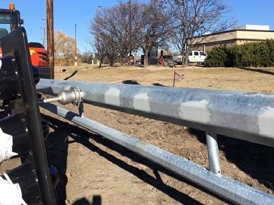
2-6

                                                                                                         SPECIFICATIONS BOOK
                     CONTRACT PROPOSAL                                                              MnDOT 2545.3A & 2565.3A - General
                  The Proposal contains “important” documents

                                              • Addendum's                                                                     The location of component parts as
                                                                                                                               indicated in the Contract ---
                                              • Notices to Bidder
                                                                                                                               “are approximate only”
                                              • Special Provisions                                                             the exact locations will be
                                                    DIVISION S (GENERAL)
                                                    DIVISION SS (SIGNALS)
                                                                                                                               established by the Engineer.
                                                    DIVISION SL (LIGHTING)
                                                    DIVISION SZ (TMS)                                                          Except Ped Ramps, Push Buttons
                                              • Drawings and Details                                                           and Signal Poles.
                                              • Attachments
                                              • Schedule of Prices

                “OTHER” SPECIFICATIONS                                                                   SPECIAL PROVISIONS
                                                                                             SPECIAL PROVISIONS ARE “ADDITIONS AND REVISIONS TO THE
                                                                                           STANDARD SPECIFICATIONS COVERING CONDITIONS PECULIAR TO AN
                                                                                                              INDIVIDUAL PROJECT”.

                                                                                            SPECIAL PROVISIONS ARE JUST THAT --- “SPECIAL” .   IF AN ITEM
                                                                                             IS ADEQUATELY SPECIFIED IN THE SPEC BOOK, PLANS, STANDARD
                                                                                            PLATES, OR OTHER CONTRACT DOCUMENTS, THEN IT IS NOT TO BE
                                                                                                       DUPLICATED IN THE SPECIAL PROVISIONS.

NOTE NO. 2: the Standard Plate specifies the requirements for anchor rods. The note
refers the Contractor to Spec. 3385 Anchor Rods. This specification is found in the Spec
Book which details the requirements for various types of anchor rod material.

 2-11

                      SPECIAL PROVISIONS                                                                 SPECIAL PROVISIONS
                                                                                                        DIVISION SS -TRAFFIC CONTROL SIGNALS
                    DIVISION SS (TRAFFIC CONTROL SIGNALS)
                                                                                               Signals Special Provisions are “SIMILAR” to the spec book format:
             DIVISION SS MAY BE THREE OR MORE “SS” SECTIONS:
                                                                                                           SS-2          Description
                                              • SS-1 Traffic Control                                       SS-2.1        General Section
                                                     Signals
                                                                                                           SS-2.2        Materials Section
                                              • SS-2 Emergency Vehicle
                                                     Preemption (EVP)                                      SS-2.3        Construction Requirements
                                                     System                                                SS-2.4        Measurement and Payment
                                              • SS-3 Traffic Control
                                                     Interconnection

                                                                                                                                                                    7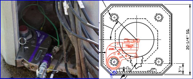
SPECIAL PROVISIONS                               SPECIAL PROVISIONS
            2565 – Traffic Control Signals                       SS-2.1 General Section

     SS-2   DESCRIPTION PARAGRAPH                            Will list the Department furnished materials

             THIS SECTION DESCRIBES:                      Will list the material that the Contractor is required to furnish
                                                          and install in order to complete the installation of the
                                                          Department furnished material.
       --- THE WORK TO BE DONE

       --- THE LOCATION OF THE WORK
                                                          This Section also includes the notification requirements of
       --- THE RULES WHICH GOVERN THE WORK                the Contractor for picking up the Department furnished
                                                          materials.

     MnDOT Electrical Services Section
                                                       SPECIAL PROVISIONS
                        ESS                                    SS-2.1 General Section
                                                  IMPORTANT REQUIREMENTS FOR THE CONTRACTOR TO
                                                                        REMEMBER:
                                                      CONTRACTOR’S RESPONSIBILITY TO OBTAIN
                                                    DEPARTMENT FURNISHED MATERIALS FROM ESS

                                                   CONTRACTOR TO DIRECT ESS TO T.E. REQUEST NO.

                                                  CONTRACTOR TO REQUEST DEPARTMENT FURNISHED
                                                   MATERIALS AT LEAST 30 NORMAL WORKING DAYS IN
                                                          ADVANCE OF CONTRACTOR NEED

                                                            SPECIAL PROVISIONS
      SPECIAL PROVISIONS                              SS-2.2 Materials Section: Service Equipment
             SS-2.1 General Section
IMPORTANT REQUIREMENTS FOR THE CONTRACTOR TO
                                                                    MnDOT projects require SSB signal service
                    REMEMBER:
                                                                    cabinets.
     CONTRACTOR’S RESPONSIBILITY TO DELIVER                         They come with or without battery backup systems.
COMPONENTS THAT NEED TO BE INSTALLED WITHIN THE
DEPARTMENT FURNISHED TRAFFIC SIGNAL CABINET TO                      The Special Provisions will refer the Contractor
   THE ELECTRICAL SERVICES SECTION AT LEAST 30                      MnDOT’s Approved Products List (APL) for the
  NORMAL WORKING DAYS IN ADVANCE OF WHEN THE                        approved SSB signal service cabinets
       CABINET IS REQUIRED ON THE JOB SITE.

 CONTRACTOR SHALL GIVE ESS AT LEAST 3 WORKING
  DAYS NOTICE OF INTENT TO PICKUP DEPARTMENT
             FURNISHED MATERIALS

                                                                                                                              8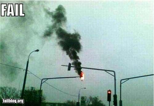
SPECIAL PROVISIONS                                           “SPECIAL PROVISIONS”
                                                                      ADVANCE WARNING FLASHERS

  THE LETTERS “I” AND “O” ARE NOT USED IN
    EITHER THE SPEC BOOK OR SPECIAL
  PROVISIONS. AS A RESULT, IN BOTH CASES,
      EACH LETTER WILL BE INCLUDED                         THE CONTRACTOR IS REQUIRED TO FURNISH AND
                                                        INSTALL THE ENTIRE ASSEMBLY. THE PLAN DETAIL AND
     FOLLOWED BY THE WORD “BLANK”.
                                                          SPECIAL PROVISIONS INDICATE ALL REQUIREMENTS

       SPECIAL PROVISIONS                                         SPECIAL PROVISIONS
              Traffic Signs and Devices                      SS-2.3 CONSTRUCTION REQUIREMENTS
                                                                         CONDUIT PLACEMENT

 MANY SIGNAL SYSTEM PROJECTS WILL INCLUDE LANGUAGE
 COVERING SIGNS THAT ARE MOUNTED ON MAST ARMS.

                                                          IN ADDITION TO THE LANGUAGE IN THE SPEC BOOK,
 THIS ITEM IS PAID FOR AS PART OF THE TRAFFIC SIGNAL
 SYSTEM AND THE REQUIREMENTS ARE SPECIFIED IN THE             SOME MnDOT DISTRICTS HAVE ADDITIONAL
 CONTRACT DOCUMENTS.                                       REQUIREMENTS FOR CONDUIT PLACEMENT. THESE
                                                            REQUIREMENTS ARE INCLUDED IN THE SPECIAL
                                                                            PROVISIONS.

       SPECIAL PROVISIONS                                         SPECIAL PROVISIONS
   SS-2.3 CONSTRUCTION REQUIREMENTS                           SS-2.3 CONSTRUCTION REQUIREMENTS
                    REMOVALS                                          REMOVAL and SALVAGE

WHEN AN EXISTING TRAFFIC SIGNAL SYSTEM IS TO BE         Removal means the contractor is responsible for removing the item
  REMOVED, THE REMOVAL REQUIREMENTS ARE                and the item then becomes the property of the contractor to properly
     SPECIFIED IN THE SPECIAL PROVISIONS.                                     dispose of the item.

THE CONTRACTOR SHALL PROVIDE A COPY OF THE ESS          Remove and Salvage means the contractor must remove the item
RECEIPT FOR SALVAGED MATERIAL TO THE ENGINEER           and return it to MnDOT at the location as defined in the contract
             FOR THE PROJECT FILE                                                documents

                                                                                                                              9
CERTIFICATION OF DISPOSAL
CONTRACTOR CERTIFICATION OF DISPOSAL
Project No.:____________ Location: ___________________________________
We, _________________________, hereby certify that the mast arm pole standards
(Name of Contractor)
were rendered unusable, and the mast arm pole standards, and if applicable, pedestal
shafts and bases were transported and disposed of in accordance with all
requirements of the Minnesota Pollution Control Agency (MPCA) and the
Occupational Safety & Health Administration (OSHA) for the removal, transporting,
and disposal of hazardous waste.
____________________________ ________________
SIGNATURE DATE
After signed and dated, the Contractor shall submit this form to the Mn/DOT project
Engineer. The Contractor shall also submit to the Engineer a copy of the “Tipping
Receipt” that the Contractor receives from the scrap yard or recycler.
SPECIAL PROVISIONS CONTRACT PROPOSAL
ADDENDUMS
•These are some samples of items that will be WHAT IS AN ADDENDUM?
included in a set of special provisions
“A supplement to the Proposal form as originally issued or printed, covering
•Each project is unique and will require additional additions, corrections, or changes in the bidding conditions for the advertised work,
that is issued by the Contracting Authority to perspective bidders prior to the date set
items not covered in this presentation for opening proposals”
•Contractors and inspectors must be aware of what Addendums are found in the front portion of the “final” MnDOT Contract Proposal
is contained in the special provisions for each
individual project
SHOP DRAWINGS APPROVED PRODUCTS MATERIALS LIST
The contract documents require that the contractor provide shop
drawings for certain electrical materials and equipment.
The distribution list is specified in the contract documents
Shop drawings must be signed off (approved) by the appropriate
MnDOT personnel prior to the contractor procuring the material.
10DEFINITION OF TERMS 1906.2 Material on Hand
Cut Sheet, Catalog Sheet, or Specification Sheet The Contractor shall provide the following actual, authentic,
A document showing a finished product including part numbers customary, and auditable documents, produced in the normal
and an ordering matrix if required. course of business, to receive payment for Materials on hand:
(1)Invoices and proof of payment for the Materials,
Shop Drawing
A detailed document showing how a specific product will be (2) An itemized list detailing the cost of Contractor-produced
fabricated and constructed. This document will also include Material, and
required material specifications and requirements.
(3) Documents containing complete Material description and
1103, 2545, and 2565. identification.
What's New Since 2015
CHAPTER 3
STANDARD PLATES
Questions ??? MnDOT is working on moving all of our details to either Standard Plans or
Standard Plates.
The general definition of a standard plan is for something constructed in the
field.
The general definition of a standard plate is for something constructed at a
manufacturing facility.
STANDARD PLATES BOOK
CHAPTER 3 •HAND OUT BOOK HAS ALL SIGNAL AND
STANDARD PLATES LIGHTING RELATED PLATES
•CHANGES PENDING AS NOTED
113-1 3-1
• STANDARD PLATES SPECIFY THE DETAILS OF
THE ITEMS TO BE FURNISHED OR
CONSTRUCTED.
• CONTRACTORS & INSPECTORS SHOULD HAVE
THESE PLATES IN THEIR POSSESSION AND BE
FAMILIAR WITH THEM
• STANDARD PLATES HAVE AN APPROVAL
PROCESS BEING ISSUED
• THEY DO NOT HAVE TO BE APPROVED ON A
PROJECT BY PROJECT BASIS
3-1 3-1
12MnDOT HAS UPDATED MANY STANDARD PLATES
THAT DEAL WITH SIGNALS AND LIGHTING
8112G - Pedestal Foundation (backfill, compact, projections)
8117F - Precast Concrete Hand Hole
8120P - Pole Foundation(backfill,compact,projections,antiseize)
8121G - Transformer Base and Pole Base Plate
8122F - Pedestal and Pedestal (shims)
8123G - Pole and Mast Arm
8126J - Pole Foundation (backfill,compact,projections,antiseize)
8127C - Light Base – Design E
(backfill,compact,projections,antiseize,foundation not base)
8128C - Light Base- Design H
(backfill,compact,projections,antiseize,foundation not base)
8309B - Reinforced Concrete Medium Barrier Type F & Glare Screen
(anchor bolts galvanized, dimensions width)
3-2
TWO WAYS TO OBTAIN STANDARD
PLATES:
STANDARD PLATES:
•GET MODIFIED
•GET DELETED
•ARE NEWLY CREATED 1. MnDOT WEB SITE: http://standardplates.dot.state.mn.us/StdPlate.aspx
2. PURCHASE THE MANUAL FROM MnDOT MAPS AND MANUAL
SALES UNIT (651-366-3017)
Office of Traffic Engineerring
Questions? Mn/DOT Sample Plan
Jerry Kotzenmacher
MnDOT
13Without a plan! Traffic Signal Plans
Office of Traffic Engineering
Office of Traffic Engineering
– Why do we need a plan?
• Building the traffic signal.
• Bidding
• Tort Claims
• Maintenance
• Locates
79 80
Title Sheet – front page Title Sheet – front page
Office of Traffic Engineering
Office of Traffic Engineering
Title Sheet – Governing Specs and Index of Sheets
– The title sheet is required for all traffic
signal plans. It includes information This defines the
such as the title block, project location, governing
governing specifications, etc. specifications for the
project, the project
funding and the
index of the sheets
contained within the
plan set.
81 82
Title Sheet – front page Sheet – front page
Office of Traffic Engineering
Office of Traffic Engineering
– Index Map
– Signature Block
The Designer should
consult with the Mn/DOT The index map
project manager to is used to
ensure that the identify the
appropriate signature location of the
block is used. project(s).
83 84
14Title Sheet – front page Title Sheet – front page
Office of Traffic Engineering
Office of Traffic Engineering
– Standard Plates Summary – Plan Symbols & Abbreviations
This identifies the list of Standard Plates that are
applicable to this project.
85 86
Title Sheet – page 2 ALL SHEETS
Office of Traffic Engineering
Office of Traffic Engineering
– Quantity Sheet
– Title Block
The title block is required on all sheets. For the
intersection layout sheet the signal system ID, meter
address and TE number should be included
87 88
Page 4- APS P. B. Station
Page 3 – Pole Mount Detail – Details
Office of Traffic Engineering
Office of Traffic Engineering
– Details
89 90
15Page 5 - Equipment Pad Controller & Service Cabinet
– Details
Office of Traffic Engineering
Office of Traffic Engineering
91 92
Page 6 -Pole Wiring Connector Page 7 – Fiber Optic Schematic
– Details – Details
Office of Traffic Engineering
Office of Traffic Engineering
93 94
Page 8 – Ped Curb Ramp
– Details Page 19 – Pavement Markings & Signs
Office of Traffic Engineering
Office of Traffic Engineering
– Details
95 96
16Page 20 – Utilities Layout Not part of your plan
Office of Traffic Engineering
Office of Traffic Engineering
– Details
97 98
Page 15 - Signal Layout Page 15– Intersection Layout
Office of Traffic Engineering
Office of Traffic Engineering
Signal Face Scale – Typical Controller Phasing Diagram
Chart
8 phase NEMA Controller
Loop Detector
Chart
Loop Conduit Road Lines
Detectors Wires conduit
3” Conduit
2-12/C/ 14
1-6/C 14
2-4/C 14
*1-3/C 14 Construction
1/3/C 14 (LUM) Notes
Ped diagram 2-2/C 14
and *1-3/C 14
Phasing 1-1/C 6 Ins. Gr
99 100
Page 16 - Signal Layout
Controller Operations
Office of Traffic Engineering
Office of Traffic Engineering
– Phasing Match line
– Dual-ring and Concurrent group Controllers
DUAL RING STRUCTURE
4
7
RING 1
Pole Notes Match line Advance Detectors
1 2 3 4
6
1
5 6 7 8
5
2
RING 2
BARRIER 1 B ARRIER 2
(LEFT SIDE) (RIGHT SIDE)
3
8
101 102
17Page 15 – Intersection Layout
Page 15 & 16 – Intersection Layout
Mast Arm & Pole _Symbols Signal Head
Office of Traffic Engineering
Office of Traffic Engineering
Indication
– Equipment Pad and SOP
Notes Signal Head
Number
Emergency Vehicle
Pre-emption
Luminaire
Mast Arm
Label, in a circle, the
controller cabinet or Signal Pole Base
equipment pad “A” and the
source of power “B”
103 104
Page 15 – Intersection Layout
Picture of Pole 4
Office of Traffic Engineering
Office of Traffic Engineering
Pole 4
Mast arm is 0 degrees
Signal Pole Base 105 106
Page 15 – Intersection Layout Page 15 – Intersection Layout
Pedestrian Signal
Office of Traffic Engineering
Office of Traffic Engineering
Face
– Signal Faces Table
Pedestrian Push
Button 107 108
18Page 15 – Intersection Layout Page 15 – Intersection Layout
Office of Traffic Engineering
Office of Traffic Engineering
– Loop Detectors Table – Handhole Labeling
Number handholes clockwise Handhole 1
with respect to
the controller cabinet with Number 1 being
adjacent to or near the controller cabinet. It
isHandhole 17
not necessary to use H.H.
Handhole 16
109 110
Page 18 – Field Wire Diagram
Page 17 – Field Wire Diagram
Handhole 14 Ped station Pole 1 12/c 14 wire
(2nd Sheet of Wire Diagram) Cable 46
Office of Traffic Engineering
Office of Traffic Engineering
Controller Heads 5-1
w/loop Detectors PB2-1
cabinet And 2-3
Controller
cabinet All cables
Have numbers
Grounded
Cable 46 Ins. GR.
Handhole 17
Ground connect
Heads 5-1 Ground rod
Service cabinet And 2-3
Notes 111 112
Wire Diagram to Layout
Wiring Diagram Cross reference
Office of Traffic Engineering
Office of Traffic Engineering
Field Wiring
113
page 18 page 15 114
19Wiring
Interconnect layout – NOT PART OF YOUR PLAN
Notes
Office of Traffic Engineering
Office of Traffic Engineering
– Field Wiring
– Traffic Control Interconnect Layout
1:100 Scale
Include a North Arrow
Include a Scale Graphic
Include General Notes
Clearly Show Guardrail
Roadway
Guardrail
10' min. 10' min.
2' min.
Conduit
Interconnect
115 116
Other Material Reference
Office of Traffic Engineering
Office of Traffic Engineering
•MnDOT Manuals
•Signal Design Manual
•Roadway Lighting Manual
•Signal Timing Manual
•Traffic Engineering Manual Questions?
•MN-MUTCD
118
117
CHAPTER 4
PLANS
Typical Lighting Plan
20Direct Buried Lighting Cable
Pole Number
Ground Rod
21Questions ?
Approved Products List (APL)
State Furnished Material
Contractor Furnished Material
Steve Grover – MN/DOT
Materials Lab
22Signal Items:
APL Can be found on line: •LED Indications
http://www.dot.state.mn.us/products/ •Paint
(In Appendix pages 40 - 41 of manual) •EVP
•Signal Heads
•Loop splice kits and Sealant
Items on the APL meet all standards and
•Hand Holes/covers
specifications without further testing.
•Pedestrian buttons
•Cabinets (SSB) /Batteries/UPS
Why an APL?
Roadway Lighting Items:
Signals – Cabinet and Controller
Lamps (need TE Number)
Screw-in Light Foundations
Luminaires Lighting – Smart Photo Control
Service Cabinets
Why State Furnished?
Hardware - holders/splice blocks/Photo Cells/fuse
kits
Must use either APL or Specs Steve Grover
Material pre-inspected MN/DOT - Materials Lab
Materials List (starts on Appendix 17)
236-1 6-1 & 6-2
GOPHER STATE ONE CALL
CHAPTER 6 (GSOC)
GOPHER STATE ONE CALL
What is it?
It’s a state wide one call center for anyone who engages in any
type of excavation using machine-powered equipment of any
kind, to file a locate request at least 48 hours, excluding
weekends and holidays, before excavation can begin. Excavator
may notify up to 14 calendar days before excavation.
GSOC Handbook Pg. 1
6-1 GSOC
GSOC Handbook- Page 3
Handbook
GSOC -What is it? GSOC Handbook Pg. 2
Once a locate is filed by the excavator, GSOC notifies those
facility operators who have joined Gopher State One Call What GSOC Doesn’t Do:
Main Points:
• It doesn’t physically locate and mark any underground facilities.
• It doesn’t settle disputes between excavators and facility
operators.
The cost of GSOC is paid by the operators and the service • It doesn’t maintain a database of exact location of underground
provided by GSOC is free to excavators. facilities.
GSOC GSOC
Handbook Handbook
GSOC Handbook Pgs. 4-5 Definitions of “Excavator” and “Operator” in accordance
with Minnesota State Law Chapter 216 D
• GSOC ITIC allows locate requests via the internet 24/7
• Emergency locates by phone 24 hours a day EXCAVATOR: (Handbook Pg. 66)
• Process locates and meets by phone: A PERSON WHO CONDUCTS EXCAVATION IN THE STATE
April- October M-F 6am- 6pm
November- March M-F 7am-5pm OPERATOR: (Handbook Pg. 67)
A PERSON WHO OWNS OR OPERATES AN UNDERGROUND
FACILITY
24GSOC GSOC
Handbook Handbook
Pg. 95
EXCAVATORS RESPONSIBLITIES Pg.16 EXCAVATORS RESPONSIBLITIES
White Marks
GSOC Handbook Pg. 16
Main Points:
• The excavator is required to use white markings to define the
GSOC Handbook Pg. 95 entire area where excavation will occur.
The Minnesota Rules in 7560.0350 sets forth requirements for a meet
• Include a safety buffer when marking the area.
• Break large projects down into multiple tickets.
GSOC
Handbook
Pg. 16 EXCAVATORS RESPONSIBLITIES
EXCAVATORS RESPONSIBLITIES When White Marks Are Not Practical
GSOC Handbook Pg. 16
Excavators are required to use white markings for indicating the area What to do
of proposed excavations unless it can be shown it is not when there is
practical snow?
6-8 6-8
MnDOT 1507.2 MnDOT Division S Special Provisions
Standard Specifications for Construction Failing to Use White Marks
Requiring White Marks
1507.2 NOTIFICATION
S-27.2 Any work performed by the Contractor that does not comply
The Contractor shall fulfill all the obligations of an excavator in Minnesota Statutes with MnDOT 1507.2 may be considered Unauthorized Work in
Chapter 216D and rules adopted to implement that statute. The Contractor's accordance with MnDOT 1512.2.
obligations include but are not limited to marking the proposed excavation, contacting
“Gopher State One Call” at least 48 h before starting excavation operations (excluding
Saturdays, Sundays, and Holidays), and providing support and protection for
underground facilities in and near the construction area.
256-9 6-10
Contractors Responsibilities Repair of Damaged Underground Facilities
for locating underground facilities within the
construction limits of the project
• The law is silent with regard to how fast an Operators facility must
be repaired.
• Generally the operator will facilitate and take charge of the repair
At the pre construction (Pre Con) meeting the contractor should of it’s damaged facility.
supply detailed contact information for whom to contact when
locating is required an excavator within the construction limits of a
project
6-10 6-10
Repair of Damaged Underground MnDOT Facilities
Section 216D.06 Damage to Facility
GSOC Handbook (Pgs. 77-78) If a MnDOT roadway lighting system is damaged the following requirements
must be meet:
Lighting systems 2545.3.A
If damage due to Contractor‘s negligence occurs to electrical cable, within 24 hours replace the
entire run of lighting system
electrical cable at no additional cost to the Department.
If the damage results in the escape of any flammable, toxic, or If damage due to Contractor‘s negligence occurs to individual conductor(s) in conduit and to
the conduit, or only to the
corrosive gas or liquid or endangers life, health, or property, the conduit, within 24 hours replace all the individual conductors in the conduit and the conduit at
excavator responsible SHALL immediately notify the operator no additional cost to the Department.
and the 911 public safety answering point, as defined in section Do not splice electrical cable and bury underground.
403.02, subdivision19, and take immediate action to protect the
public and property. Do not splice damaged conductors and place back in conduit.
6-10
Repair of Damaged Underground MnDOT Facilities Call GSOC Before You DIG
If a MnDOT traffic control signal system is damaged the following
requirements must be meet.
Signal Systems 2565.3B
If existing electrical system components are damaged due to Contractor operations, within 24
hours repair or replace the
damaged components at no additional cost to the Department, in accordance with 1716 and
relevant to specifications for new
construction.
Failure to repair or replace damaged components within 24 hours will result in the Department
repairing or replacing and deducting costs from project money entitled to the Contractor.
Your Life and the life of those working on or around
the project area depend on it.
26CHAPTER 7
QUESTIONS?
TRAFFIC CONTROL
7‐1
Shortest Construction Zone Ever !
Examples of "Acceptable" warning signs
FIELD MANUAL HAS SPECIFIC REQUIREMENTS FOR ALL TYPES OF
LANE CLOSURES
YOU WILL ALSO FIND REQUIREMENTS FOR THE SAFETY EQUIPMENT
WHICH INCLUDES VESTS, PANTS, CONES, BARRELS AND SIGNS
27Examples of "Marginal" warning signs Examples of "Unacceptable" warning signs
Examples of "Unacceptable" Channelizing Devices Some projects may require signed Pedestrian Detours
7‐3 7‐3
When closing lanes in the Twin Cities Metro Area consult the Lane The District 6 Allowable Lane Closure Manual
Control Manual (LCM) for approved lane closure time windows. Segments can be found by following the link below.
http://www.dot.state.mn.us/d6/trafficlaneclosuremanual/index.html
28TRAFFIC CONTROL IS THE RESPONSIBILITY OF THE CONTRACTOR
IN MOST CASES TRAFFIC CONTROL IS PAID FOR AS A SEPARATE
FOR THE SAFETY OF THE WORKERS PAY ITEM
AND THAT OF THE MOTORING PUBLIC
THESE REQUIREMENTS MUST BE OBSERVED MnDOT DOES OFFER CLASSES FOR TRAFFIC CONTROL AND
FLAGGERS
INFORMATION MAY BE FOUND AT THE MnDOT WORK ZONE
SAFETY WEB SITE
http://www.dot.state.mn.us/const/wzs/training.html
7‐4
7.2 Chapter 7 Resources
MnDOT also offers Work Zone Safety Training Courses at the following website:
www.dot.state.mn.us/const/wzs/training.html
MnDOT’s Temporary Traffic Control Zone Layouts Field Manual
http://www.dot.state.mn.us/trafficeng/publ/fieldmanual/
Temporary Traffic Control Zone Layouts Field Manual ordering information found at:
www.dot.state.mn.us/mapsales
Metro Lane Closure Manual
QUESTIONS ?
http://www.dot.state.mn.us/metro/trafficeng/laneclosure/index.html
MnDOT also offers Work Zone Safety Training Courses at the following website:
www.dot.state.mn.us/const/wzs/training.html
8‐1
Staking Signal System
• On most projects MnDOT’s District Traffic Office stakes the
signal system. District Traffic Office works with the survey
CHAPTER 8 crew and ADA office and verifies the staked locations.
STAKING
• Locations of some components on the plan are approximate
Traffic Control Signal Systems only.
• Signal poles and ped stations are staked according to X and
Y coordinates provided in the plan. The ADA office must be
notified of ramp and ped station construction.
29Items To Consider When Staking
• When staking the signal pole, correctly position the left turn signal head by
adding 2 feet for the pole width plus the length of the mast arm. 8‐2
• The minimum set back for signal pole foundations is 6 feet from edge of curb.
QUESTIONS?
• When staking the location of the loop detectors, use the distances given in the
chart and measure from the crosswalk (or stop bar to the front edge of the
loop). 8‐4
• In new construction areas the curb and gutter should be installed before
installing the new traffic control signal system. 8‐4
• Contact the district traffic office to confirm the staked locations before
excavating. 8‐6
8‐7 Staking Lighting Systems
LIGHT POLES
• For best placement of light pole foundations- roadway, shoulders,
and ditches should be established before staking locations.
CHAPTER 8
• The District Traffic Office will stake light pole foundation
STAKING locations that require an offset.
Lighting Systems
• Provide the District Traffic Office or the survey crew plenty of
notice before planning to excavate and install foundations.
Staking Light Poles
8‐7 8‐6 and 8‐7
Offset Detail Sheet
Light poles are staked according to the stationing found on the Light
Standards Summary Table shown on the lighting plan.
In addition to stationing, breakaway light poles require an offset
when staking. OFFSET MEASURED FROM
EDGE OF DRIVING
LANE (FOG LINE)
308‐8 When Not To Use The Maximum Distance 8‐8
Items To Consider When Staking
Avoid placing light poles in ditches. Use the minimum offset
distance if possible or contact the District Traffic Office.
Locations can be moved maximum 10 feet in either direction parallel
to the roadway if there is an obstruction.
8‐9 Items To Consider When Staking 8‐9 Items To Consider When Staking
Clearance between the back of guardrail and the front of light poles
Light poles should not be closer than 20 feet in any direction from
should be at least 4 feet and no more than 7 feet.
power lines.
What’s New Since 2015
QUESTIONS?
CHAPTER 9
EXCAVATION
AND
BACKFILL
31What’s New Since 2015
New -2018 Spec. Book Language Change
For 2451.3.D Backfilling and Compacting Excavations
CHAPTER 9
Old
Uniformly distribute suitable backfill materials in layers EXCAVATION
no thicker than 8 inch loose measurement. Compact AND
the backfill………. BACKFILL
New
Uniformly distribute suitable material in horizontal layers of no more than
6 inch compacted layers.
9‐1 Excavation and Backfill 9‐1 Excavation and Backfill
Keep the excavated area to a minimum necessary to do the work.
Over-Excavation
9‐1
Excavation and Backfill
9‐1 and 9‐2 Excavation and Backfill
Compaction
Excavate at a distance from the edge of roadway without damaging or
undermining the roadbed. Place backfill material in horizontal compacted layers not more than
6 inches thick to ensure proper compaction around foundations,
handholes and conduits.
32Compaction
What is compaction?
UNCOMPACTED SOIL COMPACTED SOIL
9‐2 Compaction
Compaction
Compaction Compaction
Issues with over-excavation and improper compaction around precast light
foundations has led to new installation requirements (Covered in Chapter 10
Foundations).
339‐2 Excavated Material and Work Zone Hazards
The contractor and inspector must not allow unprotected hazards to exist for
motorists or pedestrians during the construction of the project.
QUESTIONS?
“WHAT’S NEW SINCE 2015”
What's New Since 2015
CHAPTER 10
FOUNDATIONS AND EQUIPMENT PADS
The New 350 ATC Cabinet Pad is Required in 2020
“WHAT’S NEW SINCE 2015” “WHAT’S NEW SINCE 2015”
The New 352 ATC Cabinet Pad Will be Required When an Agency
Wants to Use a Single Wide Cabinet There will soon be revised standard plates for Design E and H Foundations
There will be a new Design P Standard Plate.
34“WHAT’S NEW SINCE 2015” “WHAT’S NEW SINCE 2015”
NEW INSTALLATION REQUIREMENTS FOR PRECAST
CONCRETE LIGHT FOUNDATIONS DESIGN E AND DESIGN H
SPECIAL REQUIREMENTS WHEN A FULL LENGTH FIBER
FORMING TUBE IS USED FOR MAST ARM PA POLE
FOUNDATIONS
“WHAT’S NEW SINCE 2015” “WHAT’S NEW SINCE 2015”
STEEL SCREW IN LIGHT FOUNDATIONS DESIGN E AND H
AND INSTALLATION REQUIREMENTS. SPECIFICATION LANGUAGE FOR LIGHT POLE
FOUNDATION GRADING ON ROADSIDE SLOPES.
“WHAT’S NEW SINCE 2015”
RLF EQUIPMENT PAD DETAIL HAS BEEN CONVERTED INTO
STANDARD PLATE 8107 WITH THE OPTION TO USE
PRECAST
Chapter 10
FOUNDATIONS
AND
EQUIPMENT PADS
TYPE RURAL LIGHTING
AND FLASHER (RLF)
SERVICE CABINET
3510-1 Standard Specifications
Carry all the contract documents on the project 10-3
Remove the template after 24 hours of concrete placement.
3610-5 Standard Specification Requirements 10‐7 ‐ 10‐9
PA Signal Pole
3385.2. Galvanize Type A, Type B, and Type C Anchor Rods Foundations
Avoid using a full length forming
tube.
Use a forming tube for the upper
ASTM F1554 S3 requirement portion of the foundation and 4
*
steel die stamped with the grade feet below grade.
identification on the end of the ** *
anchor rod projecting from the
concrete
10‐9 and 10‐10
Mast Arm Pole Foundations 10-11
POLE FOUNDATION TYPE BA
Requirements For Using Full Length Forming
Tube- PA 85, 90, and 100 Foundations A FORMING TUBE MAY ONLY BE USED FOR
FOUR 3 IN X 12 IN RECTANGULAR HOLES FORMING THE TOP 4 FEET OF THE
DRILLED SHAFT FOUNDATION
3710‐12 PEDESTALFOUNDATION
PEDESTAL FOUNDATION 10‐13,14 APS Push Button Station Foundation
STANDARD
STANDARD PLATE 8112
PLATE 8112
The projection of the Pedestal
Foundation no more than a ¼ STD. PLATE 8122
inch above the concrete sidewalk
or finished grade.
Min 9”
10‐18 10-17,18 Light Foundation Design E and H
Light Pole Foundations 3 5/8 inch min. to a 4
inch max. anchor rod
projection.
Cast In‐ Place Concrete Precast Concrete Steel Screw‐In
Foundation Flush With
Ground Line or
Finished Grade
AASHTO 4 Inch Max.Stub
Height Requirement
38INSTALL LIGHT FOUNDATIONS FLUSH WITH GROUND LINE
INSTALL LIGHT FOUNDATIONS FLUSH WITH GROUND LINE INSTALL LIGHT FOUNDATIONS FLUSH WITH GROUND LINE
INSTALL LIGHT FOUNDATIONS FLUSH WITH GROUND LINE INSTALL LIGHT FOUNDATIONS FLUSH WITH GROUND LINE
3910-17,18 10-17,18
Light Foundation Design E and H (Cast In‐Place and Precast)
Conduits with end bells project minimum ¼ inch to a maximum 1 inch Conduits with end bells project minimum ¼ inch to a maximum 1 inch
above the foundation
1½
IN.
¼ inch – 1 inch
NOT IN THE 10-21, 22
FIELD GUIDE
Installation Precast Light Foundation Design E and H Steel Screw In Light Foundations Design E and H
Installation Requirements
30”‐36” Dia.
Installers of steel screw-in foundations are required
Drilled Shaft
to be trained and certified every two years by the
manufacturer or the manufacturer’s representative.
Fill Annular
Use a hydraulic drive head with a gear motor
Void With Fine
minimum torque rating of:
Filter Aggregate
10,000 ft. lbs. for Design E
or Lean Mix
15,000 ft lbs. for Design H
Backfill
Contractor is responsible to perform onsite field
review of soils and obtain soil test reports.
10-24, 25
Steel Screw In Light Foundation Installation Detail Sheet
Steel Screw In Light Foundation Installation Video
4010-27
Precast Equipment Pads Precast Equipment Pads
(B 8106 and RLF 8107) (B 8106, RLF 8107,)
DO NOT USE MECHANICAL ANCHOR BOLTS
OR CONCRETE WEDGE ANCHORS
USE EPOXY ADHESIVE ANCHORS.
10-29 LIGHT FOUNDATION GRADING ON ROADSIDE 10-29, 30 Installing Foundations On Roadside Slope
“……..Shape the terrain around the foundations to ensure anchor rods do not
project more than a maximum of four (4) inches above a horizontal line between
the straddling wheels of a vehicle on 60 inch centers.”
41CHAPTER 11
Questions?
CONDUITS AND FITTINGS
11-1 and
11-2 INSTALLATION REQUIREMENTS 11‐2
INSTALLATION REQUIREMENTS
•Directional boring is the preferred method of installing conduit MnDOT Liquid Tight LFNC-B Conduit Requirements
under roadway surfaces. HDPE conduit is the preferred conduit. MnDOT 3804
•Refer to the Contract documents for Rigid PVC or HDPE conduit
installation requirements
•If Rigid PVC is used under the roadway Long Line couplings must be
used to join the conduit.
Type LFNC‐B.
NRTL Listed and labeled in accordance with UL standard 1660.
Listed for 80° C (176°F) in a dry location.
Listed for 60° C (140°F) in a wet location.
•If boring operations are abandoned for Listed for 70° C (158°F) in an oily location.
any reason, the voids must be grouted. Sunlight resistant.
Rated for outdoor use.
CSA certified for use at 75° C (167°F) in dry and oily locations and for minus 18° C (0° F) low
temperature applications.
Shall not have a metallic integral reinforcement within the conduit wall.
4211-2 11-2
TYPES OF CONDUITS TYPES OF CONDUITS
There are 3 main types of conduits used on signal
and lighting systems: MnDOT 3805
MnDOT now requires PVC coated hot-dipped
• Rigid Steel (RSC)- 3801 galvanized rigid steel conduit and fittings be
• Non-Metallic Conduit- 3803 installed on bridges.
• PVC Coated Hot Dipped Galvanized RSC- 3805
“On bridges” includes:
• Concrete Encased
• Hanging
• Surface Mounted
(2565.3.D.6)
REMEMBER THIS
11‐3 11‐3
ABOVE GROUND CONDUIT
Conduit Size Not Specified In The Contract
When conduits are attached to wood poles, the
2565.3 D.1
conduit must be secured with two-hole conduit
If the contract does not specify the size of conduit, provide straps that meet the National Electrical Code (NEC).
conduit at least ¾ inch and sized so the area occupied by the
electrical cables and conductors does not exceed 40 percent
of the internal cross-sectional area of the conduit for rigid steel
conduit or 35 percent for non-metallic conduit
UNDERGROUND CONDUIT INSTALLATION Open Ends
11‐5 11‐7
Underground conduit must be placed no less than 18 inches below 2565.3D.2.b requires that open ends of conduits in
the surface of any ground area and not less than 24 inches below any cabinet pads and pole foundations must be sealed
roadway surface after the installation of the cables and conductors
with an approved sealing compound.
43EXPANSION & DEFLECTION/EXPANSION
11‐8
FITTINGS
Expansion Deflection/Expansion
QUESTIONS?
The 2016 Standard Specifications for Construction require the
expansion and deflection/expansion fittings to be PVC coated.
MnDOT 3839
“WHAT’S NEW SINCE 2015”
MnDOT HAS A NEW HANDHOLES LISTED ON THE APL
What's New Since 2015
CHAPTER 12
HANDHOLES, PULLING VAULTS
AND
JUNCTION BOXES
12-2
HANDHOLE INSTALLATION
Chapter 12
COARSE FILTER
Handholes AGGREGATE
Pulling Vaults
&
Handholes are to be placed on a compacted rock
Junction Boxes (coarse filtered aggregate) drain bed as specified in
the contract documents
4412-2 12-3
HANDHOLE INSTALLATION HANDHOLE INSTALLATION
Excavation for each handhole must be backfilled Keep handholes away from structures to ensure
around the installed handhole and the backfill proper compaction around handhole
material must be like kind to adjacent soils and
compacted to approximately the same density.
The cover must be in place prior to backfilling
around the handhole.
12-3
HANDHOLE INSTALLATION HANDHOLE INSTALLATION
Conduits terminating in handholes must extend
2 to 3 inches beyond the inside wall of the handhole
Handholes must not be placed on roadway
shoulders
12-4
HANDHOLE INSTALLATION HANDHOLE TYPES
12‐4
Direct buried lighting cable entering or exiting a handhole must have
conduit stub outs.
There are two types of MnDOT handholes
Stub outs must be a 2-inch conduit and a minimum 36 inches long.
End bells must be installed on both ends of the conduit • HANDHOLES FOR NON-DELIBERATE HEAVY
VEHICULAR TRAFFIC (commonly used)
• HANDHOLES FOR DELIBERATE HEAVY
VEHICULAR TRAFFIC (rarely used)
4512-4
HANDHOLE TYPES HANDHOLES LISTED ON MnDOT's APL
CONSIST OF THREE PARTS
BOX (BASE), EXTENSION, AND COVER
COVER
HANDHOLES FOR NON-DELIBERATE HEAVY VEHICULAR
TRAFFIC ARE LISTED ON MnDOT’s APPROVED PRODUCTS LIST
(APL) FOR SIGNALS AND LIGHTING
EXTENSION
BODY (BARRELL)
12-5 12-6
HANDHOLE TYPES BALL LOCATORS
HANDHOLES FOR DELIBERATE HEAVY VEHICULAR TRAFFIC IS A MnDOT, including the RTMC, require “ball locators”
PRECAST CONCRETE HANDHOLE STANDARD PLATE 8117. in handholes.
ONLY USE WHEN THE HANDHOLE MUST BE INSTALLED IN THE
ROADWAY DRIVING SURFACE
BALL ON
A STICK
Ball locators should be installed on a ¾ inch PVC conduit so the
ball will be within six inches from the top of the handhole.
12-6
BALL LOCATORS
When specified in contract documents, ends of
conduits (without handholes) will require RED “ball
locators” as specified in the Contract documents
lighting systems
QUESTIONS?
46“WHAT’S NEW SINCE 2015”
GROUNDING FOR HIGH MAST LIGHTING TOWERS
HAS BEEN CHANGED
What's New Since 2015 F.3.a Grounding Systems for Mat Foundations
(1) Lightning protection conductors specified on the Plan
(2) Four 10 foot ground rod electrodes in accordance with 3818 per foundation
CHAPTER 13 (3) Two bronze bonding lugs for each high mast lighting unit sized
(a) For the lightning protection conductors
GROUNDING AND BONDING (b) To fit on to the HMLT base bonding studs and under the nuts for a tight connection.
F.3.b Grounding Systems for Pile Foundations
(1) Lightning protection conductors specified on the Plan
(2) Two exothermic grounding connectors for each pile foundation as shown on the
Plan sized for the lightning conductors and designed for welding to the pile used on the
Project
(3) Two bronze bonding lugs for each high mast lighting unit sized
(a) For the lightning protection conductors
(b) To fit on to the HMLT base bonding studs and under the nuts for a tight connection
“WHAT’S NEW SINCE 2015” “WHAT’S NEW SINCE 2015”
GROUND ROD LENGTH CHANGES FOR TRAFFIC SIGNAL AND 12 FT GROUND RODS ARE USED INSTEAD OF 15 FT WHEN
LIGHTING SYSTEM FOUNDATIONS AN EQUIPMENT PADS GROUND RODS ARE REQUIRED IN TRAFFIC SIGNAL HANDHOLES
SEE THE SPECIAL PROVISIONS IF 10 FT AND 12 FT GROUND RODS
SEE SPECIAL PROVISION FOR ARE APPROVED ON THE PROJECT.
THE CHANGE FROM 15 FT TO
10 FT IN TRAFFIC SIGNAL
AND LIGHTING SYSTEM
FOUNDATIONS AND
EQUIPMENT PADS
* WILL REMAIN 15 FT IN SEE SPECIAL PROVISIONS FOR THE
BARRIER LIGHT POLE CHANGE FROM 15 FT TO 12 FT
FOUNDATIONS GROUND RODS IN TRAFFIC SIGNAL
HAND HOLES
“WHAT’S NEW SINCE 2015”
GROUNDING ELECTRODES INCLUDE GROUND
RODS AND PLATES DEFINED IN MnDOT 3818
CHAPTER 13
GROUNDING AND BONDING
4713-1
CABLE FILLER
All bonding and grounding must be in accordance with
Article 250 of the National Electrical Code (NEC)
13-1
CAST-IN-PLACE EQUIPMENT PAD “GROUNDING ELECTRODE
DEFINITIONS: 13-1
SYSTEM” FOR TRAFFIC SIGNAL AND LIGHTING SYSTEMS
Bonding:
Is defined in the NEC as a permanent joining of metallic
parts required to be electrically connected NO REINFORCEMENT BAR
TO BOND TO
Grounding:
Is defined in the NEC as a conducting connection, whether
intentional or accidental, between an electrical circuit or
equipment and the earth or to some conductive body that
serves in place of earth
PRECAST EQUIPMENT PAD “GROUNDING ELECTRODE SYSTEM”
13-1
FOR TRAFFIC SIGNAL AND LIGHTING SYSTEMS INSTALLING A SUPPLEMENTAL GROUND ROD IN HANDHOLE
SEE SPECIAL PROVISIONS FOR THE
CHANGE FROM 15 FT TO 12 FT
MUST BOND TO GROUND GROUND RODS IN TRAFFIC SIGNAL
THE REINFORCEMENT BAR HAND HOLES
AS PART OF THE
GROUNDING ELECTRODE
SYSTEM
4813-2 13-2 and
EXOTHERMIC WELDING 13-3 GROUNDING CONDUCTORS FOR TRAFFIC
SIGNALS
Bond ground rod electrodes in hand holes to the
6 AWG insulated green equipment grounding conductor by All new traffic signal systems require a 6 AWG green insulated
exothermic welding for traffic signal systems . stranded grounding conductor from the signal cabinet to each pole
base (See Figures 13-7 AND 13-8)
6 AWG green insulated stranded bonding jumpers and grounding
electrode conductors are required for traffic signal systems.
13-2
BONDING POLE BASES 13-3 and
13-4 OXIDE INHIBITOR AGENT
Use an active clamping grounding lug with mounting Oxide inhibitor agent in accordance with 3843 must be applied to all
tang in traffic signal and light pole bases. (traffic signals and lighting) grounding connections before assembly
INCORRECT CORRECT and after final connection.
13-4
SUPPLEMENTAL GROUND RODS AT LIGHT 10 FT GROUND RODS FOR LIGHT FOUNDATIONS EXCEPT……
FOUNDATIONS
MnDOT Spec. 2545.3.R “Bonding and Grounding”
Provide ground rods at every other light foundation and at the light
foundations located at both ends of a run.
4913-4
15 FT GROUND RODS IN BARRIER LIGHT Grounding and Bonding Direct Buried
FOUNDATIONS Lighting Cable
IN THE LIGHT POLE BASE THE
COPPER SHIELDING AND
GROUNDING CONDUCTOR MUST
BE BONDED TOGETHER BY
DRILLING THE SHIELDING AND
PLACING IT UNDERNEATH AN
ACTIVE CLAMPING GROUNDING
LUG WITH TANG. BOLT ASSEMBLY
TO POLE BASE PLATE. TERMINATE
GROUNDING CONDUCTOR IN THE
ACTIVE CLAMPING GROUNDING
LUG.
6 AWG SOLID BARE BONDING JUMPERS AND
GROUNDING ELECTRODE CONDUCTORS ARE REQUIRED
FOR LIGHTING SYSTEMS.
GROUNDING COPPER PLATE ELECTRODE
GROUND ROD
INSTALLATION
Drive ground rods to a
depth not less than 10
feet
If rock is encountered
drive the ground rod
no more than 45
degrees from vertical
If more than 45
degrees bury in a If it is not possible to install ground rods according to the installation
trench that is at least requirements of the NEC, install grounding copper plate electrodes in
30 inches deep DO NOT CUT GROUND RODS!
accordance with MnDOT Spec. 3818
GROUNDING REQUIREMENTS FOR HIGH MAST LIGHT PILE FOUNDATION 13-5
13-5
IN PLANS AND HIGH MAST SPECIAL PROVISIONS GROUNDING GRID
UPDATED REQUIREMENTS FOR HIGH
INFORMATION TO MAST LIGHT FOUNDATION MAT
REPLACE ON PAGE DESIGN IN PLANS AND HIGH
13‐5 IN THE FIELD MAST LIGHTING SPECIAL
GUIDE PROVISIONS
UPDATED INFORMATION TO
REPLACE ON PAGE 13‐5 IN
THE FIELD GUIDE
50What's New Since 2015
QUESTIONS? CHAPTER 14
WIRING
“WHAT’S NEW SINCE 2015” “WHAT’S NEW SINCE 2015”
MnDOT now requires that only split bolts be used for
SPEC. 3806 UNDERGROUND NON-DETECTABLE
splicing neutral conductors in light pole bases.
MARKING TAPE REQUIREMENTS
“WHAT’S NEW SINCE 2015” “WHAT’S NEW SINCE 2015”
USE A 2 AMP FAST ACTING FIBER TUBE SPEC. 3843 ANTI-OXIDANT JOINT COMPOUND
CARTRIDGE FUSE IN LUMINAIRE FUSE HOLDERS Provide anti-oxidant
joint compound for
conductor
terminations as
specified in the
Contract to prevent
corrosion and
oxidation, and
improve conductivity
and the integrity of
electrical
connections.
51“WHAT’S NEW SINCE 2015” “WHAT’S NEW SINCE 2015”
SPECIFICATION LANGUAGE IN THE SPEC BOOK TO
INSTALL DIRECT BURIED LIGHTING CABLE IN PVC OR REMOVING DIRECT BUIRED LIGHTING CABLE SHOULD NOW BE A SEPARATE
HDPE CONDUIT WHEN NOT LOCATED UNDER TOP SOIL. PAY ITEM ON ALL PROJECTS THAT REQUIRE CABLE REMOVAL
2545.3.G.2
Install direct buried lighting cable in rigid PVC or Remove Direct Buried Lighting Cable
HDPE conduit if located under bituminous,
concrete, or other material not considered a top soil. Remove direct buried lighting cable as indicated in the Plan is measured by the
Provide 3 in conduit if the contract does not specify linear foot. Direct buried lighting cable is paid for under pay Item No. 2104.503
size of conduit. (REMOVE DIRECT BURIED LIGHTING CABLE) at the Contract price per
LINEAR FOOT, which price is compensation in full.
14-1
General Wiring Requirements
Traffic Control Signal and Lighting Systems
CHAPTER 14
WIRING • All cables and conductors must conform to the NEC. MnDOT requirements
may exceed those of the NEC.
• A few general MnDOT wiring requirements in 3815 for cables and individual
conductors:
NRTL Certified (exception is loop lead‐in and EVP cable)
Insulation rated for 600V
Meeting requirements of ANSI, ASTM, and ICEA/NEMA
Wire sizes for conductors based on the AWG
14-2 14-2
Inspection of Cables for Traffic Control Inspection of Cables for Traffic Control Signal
Signal and Lighting Systems and Lighting Systems
• Cables are usually inspected at the distributer by the MnDOT Materials Lab.
• Cut sheet showing the project number, reel number, and MnDOT test number • Ensure a cut sheet is provided so the cable can be tracked where it comes from
will be included with each project shipment. and shows that it has been tested by the MnDOT Materials Lab.
• Any cables not having the inspection documentation must be sampled and • Cables must be inspected and approved before installation.
submitted to the MnDOT Materials Lab.
52You can also read