POWER AND CONTROLS CONTROL
←
→
Page content transcription
If your browser does not render page correctly, please read the page content below
POWER AND CONTROLS
             CONTROL

                                                                 PCD5501

EN    Dometic Interact - Triple-E 2021 Unity Rear Lounge
      Operation Manual . . . . . . . . . . . . . . . . . . . . . . . . . . . . . . . . . . . . 2

FR    Dometic Interact - Triple-E 2021 Unity Rear Lounge
      Manuel d’utilisation . . . . . . . . . . . . . . . . . . . . . . . . . . . . . . . . . . 30

         WARNING
Cancer and Reproductive Harm
 www.P65Warnings.ca.gov                                Revision A Form No. 3317348.002 | 11/2020 | ©2020 Dometic Corporation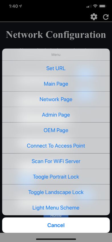
Contents                                                                                                                                Dometic Interact

Service Center & Dealer Locations
Visit: www.dometic.com
Read these instructions carefully. These instructions MUST stay with this product.

Contents
1 Explanation of Symbols and                                                         4.2 Mobile Application Navigation and Use. . . . . 24
  Safety Instructions . . . . . . . . . . . . . . . . . . . . . . . .3                      4.2.1 Prerequisites . . . . . . . . . . . . . . . . . . . . 24
    1.1 Recognize Safety Information . . . . . . . . . . . . . . .3                         4.2.2 Initial Connection. . . . . . . . . . . . . . . . . 25
    1.2 Understand Signal Words . . . . . . . . . . . . . . . . . .3                        4.2.3 Password and SSID Settings . . . . . . . . 25
    1.3 Supplemental Directives . . . . . . . . . . . . . . . . . . .3                      4.2.4 Navigation and Use . . . . . . . . . . . . . . . 26
    1.4 General Safety Messages . . . . . . . . . . . . . . . . . .3
                                                                                  5 Maintenance . . . . . . . . . . . . . . . . . . . . . . . . . . . 27
2 General Information. . . . . . . . . . . . . . . . . . . . . . .3                  5.1 Care and Cleaning . . . . . . . . . . . . . . . . . . . . . . 27
    2.1 Key Features . . . . . . . . . . . . . . . . . . . . . . . . . . . . .4      5.2 Preventive Maintenance. . . . . . . . . . . . . . . . . . 28
3 Intended Use. . . . . . . . . . . . . . . . . . . . . . . . . . . . .4          6 Troubleshooting. . . . . . . . . . . . . . . . . . . . . . . . 28
4 Operation . . . . . . . . . . . . . . . . . . . . . . . . . . . . . . .4        7 Disposal . . . . . . . . . . . . . . . . . . . . . . . . . . . . . . . 29
    4.1 Touch-Screen Navigation and Use . . . . . . . . . . .5
                                                                                  LIMITED ONE-YEAR WARRANTY. . . . . . . . . . . . . 29
           4.1.1     Main Navigation Screen and Icons. . . . .5
           4.1.2 Climate Screens. . . . . . . . . . . . . . . . . . . .6
           4.1.3 Scheduler Screens . . . . . . . . . . . . . . . . .7
           4.1.4 Mechanical Screen . . . . . . . . . . . . . . . . .8
           4.1.5 Lights Screen . . . . . . . . . . . . . . . . . . . . . .9
           4.1.6 Power Screen . . . . . . . . . . . . . . . . . . . . .9
           4.1.7 AGS Screen . . . . . . . . . . . . . . . . . . . . . . 14
           4.1.8 Tanks Screen . . . . . . . . . . . . . . . . . . . . . 15
           4.1.9 Settings Screen . . . . . . . . . . . . . . . . . . . 17
           4.1.10 Programs Screen . . . . . . . . . . . . . . . . . 20
           4.1.11 Fuses Screen . . . . . . . . . . . . . . . . . . . . . 21
           4.1.12 Bedroom Screen . . . . . . . . . . . . . . . . . 22
           4.1.13 Bathroom Screen . . . . . . . . . . . . . . . . 22
           4.1.14 Entry Screen. . . . . . . . . . . . . . . . . . . . . 23
           4.1.15 Clock Screen . . . . . . . . . . . . . . . . . . . . 23
           4.1.16 Notification Screen . . . . . . . . . . . . . . . 24

2                                                                                                                                                       EN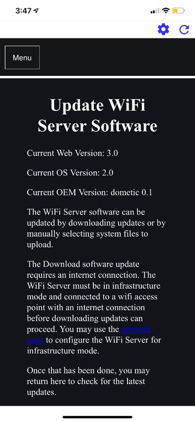
Dometic Interact                                                              Explanation of Symbols and Safety Instructions

1 Explanation of Symbols and                                   • The installation must comply with all applicable local or
                                                                 national codes, including the latest edition of the
Safety Instructions                                              following standards:
This manual has safety information and instructions to           U.S.A.
help you eliminate or reduce the risk of accidents and
                                                                  – ANSI/NFPA70, National Electrical Code (NEC)
injuries.
                                                                  – ANSI/NFPA 1192, Recreational Vehicles Code

1.1 Recognize Safety Information                                  – ANSI Z21.57, Recreational Vehicles Code
                                                                 Canada
D This is the safety alert symbol.                                – CSA C22.1, Parts l & ll, Canadian Electrical Code
     It is used to alert you to potential physical injury
     hazards. Obey all safety messages that follow this           – CSA Z240 RV Series, Recreational Vehicles
     symbol to avoid possible injury or death.
                                                               1.4 General Safety Messages
1.2 Understand Signal Words
A safety symbol and/or signal word identify safety
                                                               ! WARNING: FIRE, IMPACT, AND/OR
                                                                    EXPLOSION HAZARD. Failure to obey the
messages and indicate the hazard severity.                          following warnings could result in death or
                                                                    serious injury:
D DANGER!
     Indicates a hazardous situation that, if not avoided,     • Use only Dometic replacement parts and components
     will result in death or serious injury.                     that are specifically approved for use with the
                                                                 appliance.
! WARNING:                                                     • Avoid improper installation, adjustment, alterations,
     Indicates a hazardous situation that, if not avoided,       service, or maintenance of the appliance. Service and
     could result in death or serious injury.                    maintenance must be done by a qualified service
                                                                 person only.
! CAUTION:                                                     • Use care when diagnosing and/or adjusting
     Indicates a hazardous situation that, if not avoided,       components on a powered unit.
     could result in minor or moderate injury.
                                                               • Do not modify this product in any way. Modifications
NOTICE: Used to address practices not related to                 can be extremely hazardous.
physical injury.
                                                               • Do not allow children to play with this product or with
     Indicates additional information that is not related to     fixed controls (if applicable).
I    physical injury.

                                                               2 General Information
1.3 Supplemental Directives
                                                               Dometic Interact provides a central control and
To reduce the risk of accidents and injuries, please           monitoring hub for the appliances in your recreational
observe the following directives before proceeding to          vehicle (RV). All of the LCDs in the RV communicate with
operate this appliance:                                        each other continuously over the RV-C bus. When one
• Read and follow all safety information and instructions.     LCD is down, the others can continue to operate.

• Read and understand these instructions before                Dometic Interact does not replace the actual hardware
  operating this product.                                      controllers for the systems within the coach; it is a display

EN                                                                                                                         3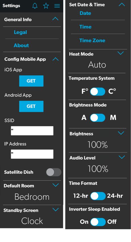
Intended Use                                                                                            Dometic Interact

that sends the signals and commands to various              3 Intended Use
components (such as load boxes) regarding the actions
that should be taken.                                       Dometic Interact is intended to be used in conjunction
                                                            with the existing control and/or monitoring devices
The Dometic Interact system allows you to:
                                                            within your RV. It creates a central hub that you can use to
• Control the climate, lighting, awnings, slide-outs,       efficiently control and monitor your appliances, via the
  water systems, and generators from convenient             onboard touch-screen display or from your mobile
  locations in and around your vehicle.                     application.

• Monitor the status of water tank levels, LP gas levels,   The manufacturer accepts no liability for damage in the
  and battery levels from any location.                     following cases:

• Predict the usage of onboard components. Predictive       • Faulty assembly or connection
  usage technology provides on-screen reporting of vital
                                                            • Damage to the product resulting from mechanical
  water and power resources, and determines when you
                                                              influences and excess voltage
  should consider refilling or recharging.
                                                            • Alterations to the product without express permission
                                                              from the manufacturer
2.1 Key Features
                                                            • Use for purposes other than those described in the
Dometic Interact has the following features and benefits      operating manual
when integrated with your RV:
                                                            Dometic Corporation reserves the right to modify
• Convenient 3.5 in. (89 mm) touch-screen display           appearances and specifications without notice.
• Wireless network control and mobile application
• Single- or multiple-screen interfaces                     4 Operation
• One-touch control for user-programmable modes,
  such as Home, Away, and Sleep                             ! WARNING:        FIRE AND/OR IMPACT HAZARD.
                                                                 Failure to obey the following warnings could
• Haptic touch and sound feedback                                result in death or serious injury:
• On-screen predictive usage                                • Avoid improper operation of the unit. Refer to the
• Control and monitoring of your RV's vital and               operating manuals for the specific products that this
  convenience features, such as:                              unit controls to understand and obey the applicable
                                                              safety precautions.
    – Lights
                                                            • Do not allow anyone (including children) with reduced
    – Climate
                                                              physical, sensory, or mental capabilities, or lack of
    – Generator                                               experience and knowledge to use this product, unless
                                                              they have been given supervision or instruction
    – Inverter
                                                              concerning the use of this product by a person
    – Water holding tanks                                     responsible for their safety.
    – Water pump
    – Water heater
                                                            I You  can use multiple screens for different operations
                                                              at the same time, but avoid performing a single
                                                                 operation from multiple screens.
    – Awning
    – Alarm clock                                           Dometic Interact can be operated from the onboard
                                                            touch-screen display, or via the mobile application
    – Coach battery                                         (available for download on most mobile devices).

4                                                                                                                   EN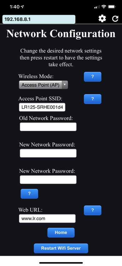
Dometic Interact                                                                                                  Operation

Refer to the following sections for more information about   • Lights Screen
touch-screen and mobile application navigation and use,
including information about:                                 • Power Screen
                                                             • Notification Screen
• UI screens and buttons
                                                             • Tanks Screen
• Control and monitoring functionality
• Prerequisites (mobile only)                                • AGS Screen
                                                             • Fuses Screen
4.1 Touch-Screen Navigation and                              • Settings Screen
Use                                                          • Room Screens
This section describes how to use Dometic Interact from      • Programs Screen
the touch-screen display.
                                                             • Clock Screen
Refer to section 1.1 Mobile Application Navigation and
Use to learn how to operate the control using the mobile     The following table describes the buttons that are used
application.                                                 for general navigation of the various screens and to select
                                                             settings.
I The  screens presented in this section vary according
  to the available appliances and the layout of your RV.     Button     Description
                                                                        Tap this icon to change the layout of the Main
                                                                        Navigation screen to list view.
4.1.1 Main Navigation Screen and Icons
                                                                        Tap this icon to change the layout of the Main
The Main Navigation screen is the default landing screen                Navigation screen to grid view.
that you will use to navigate through the various areas of              Tap this icon to close the current screen and return
the control.                                                            to the previous screen.
                                                                        Tap this icon to reach the Programs screen.

                                                                        Tap this icon to reach the Notifications screen.

                                                                        Tap this icon to reach the Scheduler Away
                                                                        options.
                                                                        Tap this icon to return to the Main Navigation
                                                                        screen.
                                                                        Use toggle buttons to enable or disable functions.

                                                                        Use tumblers to select from a list of available
                                                                        options. Tumblers can be horizontal or vertical.
                                                                        Scroll to bring the desired setting to the middle
                                                                        position.
1 Main Navigation Screen
                                                                        Use sliders to increase or decrease the intensity of
The Main Navigation screen provides access to the                       certain settings, such as light sources. Sliders can
following screens:                                                      be horizontal or vertical. Slide the dot along the
                                                                        bar to the desired intensity. The indicator shows
• Climate Screens                                                       the intensity level as a percentage.

• Mechanical Screen

EN                                                                                                                          5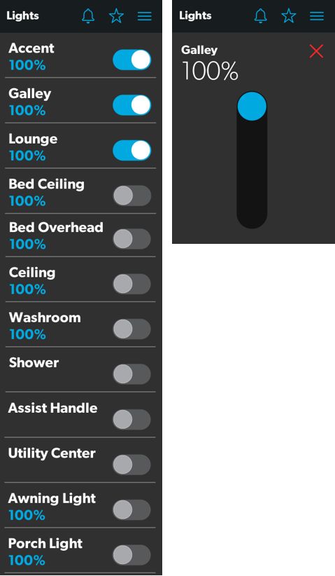
Operation                                                                                               Dometic Interact

4.1.2 Climate Screens                                       From these screens, you can manually control or monitor
                                                            the following functions:
The Climate screens allow you to control and monitor the
climate within your RV, such as cooling, heating, and air   • Current Temperatures: These indicate the current
circulation.                                                  indoor and outdoor air temperatures. The Inside and
                                                              Outside temperature values will display “- - “ if the air
                                                              temperature is outside of the sensor detection range
                                                              [< -100 or > 200 °F (< -73 or > 93 °C )].

                                                                   The outdoor temperature sensor may not be
                                                            I      available on all models.
                                                            • Power: The default state for this button is off. Tap the
                                                              toggle button once to turn climate control on. The
                                                              applicable climate control appliance will be activated,
                                                              depending on the set temperature and the
                                                              temperature type currently selected.
                                                            • Set Temperature: This area displays a set of numbers
                                                              ranging from 40–90 °F (4–32 °C) in ascending order.
                                                              Use the tumbler to select your desired temperature
                                                              setting.
                                                            • Climate Mode: There are four climate mode options:
                                                              Auto, Fan Only, Heat, and Cool. Tap the center bar of
                                                              the lower section indicator to view the climate mode
                                                              settings. Use the tumbler to select your desired mode.
                                                              During the compressor wait period, a moving
                                                              snowflake or heat wave icon will appear under the
                                                              outside temperature readings to show that the
                                                              compressor is waiting to heat or cool.
                                                               – Choose Auto to allow the system to select the
                                                                 appropriate operating mode based on the
                                                                 configured settings and actual temperature
                                                                 readings.
                                                               – Choose Fan Only to turn off the AC or furnace and
                                                                 use only the fan for the AC unit.
                                                               – Choose Heat to turn on the furnace or heat pump.
                                                               – Choose Cool to turn on the AC unit.

                                                                   Refer to the Settings screen for information about
                                                            I      changing the Heat Mode setting to run the
                                                                   furnace, the heat pump, or in automatic mode.
                                                            • Fan Level: Tap the right bar of the lower section
                                                              indicator to view the fan speed settings for the AC unit.
                                                              There are four fan speed options: low, medium, high,
2 Climate Screens
                                                              and auto.

6                                                                                                                    EN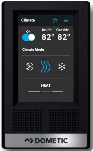
Dometic Interact                                                                                            Operation

  Use the tumbler to select your desired fan speed:         Select the clock icon to activate the Climate Scheduler.
                                                            From the Scheduler screens, you can automate the
   – Choose L, M, or H to set the fan to the low, medium,
                                                            following functions:
     or high setting.
   – Choose A to set the fan to the Auto setting, where     • Scheduler: The default state for this button is off. Tap
     the unit will determine the appropriate fan speed        the toggle button once to turn the Scheduler on. After
     automatically based on the set temperature and the       confirmation, the scheduler control will be activated
     actual temperature readings.                             based on the set temperature and time.

4.1.3 Scheduler Screens
The Scheduler screens allow you to monitor and
automatically control the climate within your RV.

                                                            4 Scheduler Confirmation Message

                                                            • Wake: The time the programmed waking temperature
                                                              will be active. Tap the display time to open the Wake -
                                                              Set Time screen and set the Wake start time. The Wake
                                                              schedule will override the manual settings until the
                                                              Scheduler is turned Off, the Sleep time is reached, or
                                                              the Away setting is activated.
                                                            • Sleep: The time the programmed sleep temperature
                                                              will be active. Tap the display time to open the Sleep -
                                                              Set Time screen and set the Sleep start time. The Sleep
                                                              schedule will override the manual settings until the
                                                              Scheduler is turned Off, the Wake time is reached, or
                                                              the Away setting is activated.
                                                            • Away: Tap the Now button once to pause the
                                                              Scheduler control temporarily. The Away temperature
                                                              will override the manual settings until the Scheduler is
                                                              turned Off, or until the Return button is selected.
                                                            • Return: Tap the Now button once to resume the
                                                              Scheduler control settings.
                                                            • Temperature: Tap the Temperature button once to
                                                              open the Temperature screen. Set the temperatures
                                                              for the Wake, Sleep, and Away environments when the
                                                              Scheduler is turned on.

3 Scheduler Screens

EN                                                                                                                     7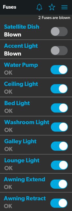
Operation                                                                                                 Dometic Interact

4.1.4 Mechanical Screen                                         • Vent Fan Speed: The Fan Speed buttons control the
                                                                  speed of the galley vent fans. Tap a button to choose
The Mechanical screen allows you to control and monitor           the desired vent fan speed from the four available
your mechanical appliances, such as awnings and                   options, which represent the percentages of the
ventilation fans.                                                 maximum fan speed: 25, 50, 75, or 100.
                                                                • Awnings: The Awning buttons allow you to extend or
                                                                  retract the awning. Awnings will have no control unless
                                                                  the parking brake is engaged. If you attempt to extend
                                                                  or retract the awnings while the parking brake is not
                                                                  engaged, an alert appears.

                                                                6 Parking Brake Alert

                                                                  The Awning buttons function as follows:
                                                                  – Tap the plus button (+) to extend the awning or the
                                                                    minus button (–) to retract the awning, and a pop-up
                                                                    message appears (assuming the parking brake is
                                                                    engaged).

5 Mechanical Screen

From this screen, you can control and monitor the
following functions:
• Power: The default state for the bath and galley fan
                                                                7 Awning Clear Message
  Power buttons is off. Tap the Power button once to turn
  the fan on.                                                     – After you have verified that the awning is clear of
• Lid Control: The bath and galley fan lids are closed by           obstructions, tap the OK button. The awning is now
  default. Tap the Open or Close button for the galley or           ready to extend or retract.
  bath fan lid control to open or close the lids. A white
  outline around the button indicates the status of the lid.

       The lid must be open before the fan motor turns
I      on. If the lid is closed when you attempt to turn the
       fan motor on, the lid will open automatically.
       The fan must be off when the lid is closed. If the fan
       is on when you close the lid, the fan will turn off
       automatically.

8                                                                                                                     EN
Dometic Interact                                                                                             Operation

4.1.5 Lights Screen                                       • Dimmer/Slider: The light source intensity is
                                                            indicated when the power to the light is activated. Tap
The Lights screen allows you to control and monitor the     the intensity indicator to open the vertical slider screen,
various lighting sources throughout your RV, such as        where you can adjust the light source intensity.
accent, galley, utility lighting, and the other lights.

                                                          4.1.6 Power Screen
                                                          The Power screen allows you to monitor and control the
                                                          available power sources for your RV, such as the battery,
                                                          inverter, and generator.

8 Lights Screen

        The Shower, Assist Handle, and Utility Center
I       lights do not dim.

From these screens, you can control and monitor the
following functions:
• Power Buttons: The power buttons are used to turn a
  particular light on and off. Tap the toggle or on/off
  buttons as desired to turn the lights on or off.

                                                          9 Power Screen

EN                                                                                                                    9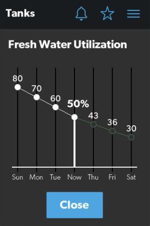
Operation                                                                                                         Dometic Interact

From the Power screen, you can control and monitor the              • Charger Stage: This indicator shows the charger
following functions:                                                  status of the onboard charger, as described in the
                                                                      following table:
• Inverter Power: Use the toggle button to turn the
  inverter ON or OFF. The Operating Mode indicator                  Number Status          Description
  displays the operating mode of the inverter:                      0          Disabled    The charger is disabled.
     – Pass Thru indicates the inverter is bypassed, when           1          Not         The charger is enabled, but it is not
       the shore power is hooked up.                                           Charging    charging (typically due to a lack of
                                                                                           AC power).
     – Inverting indicates the inverter is Enabled.
                                                                    2          Bulk        The charger is in the initial stage of
     – Waiting to Invert indicates the inverter is Enabled but                             the three-stage charging cycle.
       is not yet actually producing AC power.
                                                                    3          Absorption The charger is in the second stage of
     – Load Sensing indicates the inverter is waiting for the                             the three-stage charging cycle.
       load.                                                        4          Over        The charger is over-charging the
                                                                               Charge      batteries (this status is rare).
     The following modes display on the inverter LCD
     screen. Refer to the Xantrex Inverter Manual for more          5          Equalize    The charger is equalizing the
                                                                                           batteries.
     information.
                                                                    6          Float       The charger is in the third stage of
     – Battery mode indicates that the inverter is running                                 the three-stage charging cycle.
       and supplying AC power to the loads from battery.
                                                                    7          Constant    The charger is providing constant
     – Grid mode indicates that the inverter is charging the                   Voltage     voltage charging (typically used
       battery with AC voltage from shore power, but it is                                 during single-stage charging cycles).
       bypassing the inverter supply of AC power to the
       loads directly from the shore power.                         • Charger Current: This indicator shows the current
                                                                      that the charger is drawing from shore power.
     – Off appears when the inverter is either off, or it is in
       an error, fault, or warning state.                           • AC Input Current: This indicator shows the input
                                                                      current being drawn from shore power.
         If the inverter is in an error, fault, or warning state,
I        the error code will be indicated on the inverter           • AC Load Current: This indicator shows the current
         LCD screen in the inverter compartment.                      that the loads are drawing directly from shore power,
                                                                      bypassing the inverter.
• Battery: These indicators provide voltage readings for
  the chassis (engine) and house (coach) batteries,                 • Generator: These options control both input and
  respectively.                                                       output, so you can monitor and control the onboard
                                                                      generator:
• Load Wattage (Inverter Load Wattage): This
  indicator displays the power consumed by the load                     – The hours indicator shows the number of hours that
  from the inverter when in battery mode.                                 the generator has run.

10                                                                                                                                EN
Dometic Interact Operation
– The status indicator shows the state of the The Power screen also has a settings icon that you can tap
generator, as described in the following table: to reach the Advanced Inverter Settings screen.
Number Status Description
0 Stopped The generator is stopped.
1 Pre-Heat The generator is
preheating. This is done
prior to the cranking cycle.
2 Cranking The generator is starting.
3 Running The generator is running.
4 Priming The generator is
advancing fuel.
5 Fault There is a fault.
6 Engine Run Only The generator is running,
but not producing AC
power.
7 Test Mode This status is unused.
8 Voltage-Adjust-Mode This status is unused.
9 Fault-Bypass-Mode This status is unused.
10 Configuration-Mode This status is unused.
For a complete list of generator statuses, refer to
I the RV-C Specifications PDF.
– The START and STOP buttons control the output of
the generator. Tap the START button to start the
generator. The status changes to Cranking, and then
to Running. A pop-up message should also appear.
10 Ventilation Alert
• AGS: The Automatic Generator Start (AGS) indicator
shows the status of the auto generator: ON, OFF, or
disabled due to Quiet Time or External Activity. There
is also a CLEAR AGS button; when external activity is
detected, tap this button to override the external
activity demand and turn the AGS on. 11 Advanced Inverter Settings Screens
External activity is a mechanism used to disable the
AGS if the generator is manually stopped or started.
This is a safety feature implemented so that if you
manually stop the generator, the AGS system does not
attempt to start it up again.
EN 11Operation Dometic Interact
• LBCO Voltage: This button adjusts the voltage
setting.The default setting is 10.5 V. Tap the Edit
button to adjust the value in 0.1 V increments. The
inverter is able to recover automatically at LBCO
voltage + 0.2 V.
• LBCO Shutdown Delay Timer: This button adjusts
the shutdown timer.The default setting is 300 sec. Tap
the Edit button to adjust the value in 10-sec increments.
• LBCO Recovery Voltage: This button adjusts the
recovery voltage setting.The default setting is 13.1 V.
Tap the Edit button to adjust the value by 0.1 V
increments. Selecting a value higher than the battery’s
actual fully-charged voltage level will not activate the
auto-recovery feature. Manually reset the inverter
charger when the low-battery cut-off event occurs.
12 Advanced Inverter Settings Screens (continued)
• Power Save Time: This button sets the countdown
The advanced inverter settings are for technicians only, timer to shut down the inverter operation automatically
and a pop-up message appears when you tap the to reduce the battery discharge and to preserve the
advanced inverter icon. battery life. The countdown timer range is between 1
and 25 hours. The default setting is 25 hours. During a
continuous inverter operation, the countdown initiates
when the power from the AC load drops to less than
approximately 50 W and remains below this level.
After reaching the end of the countdown timer, the
inverter charger automatically shuts down.
• Power Save Mode: This button enables the power
save mode setting. The default setting is Off. Tap the
13 Advanced Inverter Settings Notification toggle button On to allow the inverter charger to go to
load sense mode automatically by sending short
Tap the CANCEL button to return to the Power screen, or pulses to further reduce the battery discharge. Power
tap the GO ANYWAY button to proceed to the save mode ends when a load greater than 25 W is
Advanced Inverter screen. connected.
• Output Frequency: This button adjusts the output
I There are some configurable settings available from
the inverter LCD display. frequency setting. The default setting is 60 Hz.
Depending on the country or location, tap the toggle
From the Advanced Inverter Settings screen, technicians button to change the value to 50 Hz and then turn the
can control or monitor the following functions by tapping unit Off and On again for the change to take effect.
the expand/contract arrows, toggle buttons, EDIT, and
OK buttons as applicable: • Output Voltage: This button adjusts the output
voltage setting. The default setting is 120 V. Tap the
• Inverter Ignition Control: This button adjusts the tumbler to select the value.
ignition control setting.The default setting is Off. Tap
the tumbler to select Automatic, Lockout, or Off. • Inverter Output Power Limit: This button adjusts
the wattage limit for outgoing power. The default
setting is 2 kW. Tap the Edit button to adjust the value
in 100 W increments. Use with the Inverter Output
Power Limit Timer if pairing with a lithium ion battery.
12 ENDometic Interact Operation
• Inverter Output Power Limit Timer: This button • Inverter Shutdown Recovery: This button sets the
adjusts the power limit timer.The default setting is 300 restart method if the inverter shuts down due to an over
sec. Tap the Edit button to adjust the value in temperature, overload, or short circuit condition. The
10-sec increments. Use with the Inverter Output Power default setting is a manual restart. Changing the setting
Limit if pairing with a lithium ion battery. The timer is to auto-restart will cause the inverter to attempt to
automatically disabled if the maximum limit is selected. restart automatically up to three times if a shut down
occurs. if the inverter is shut down for the fourth time,
• Transfer Mode: This button adjusts the line to battery additional restarts must be attempted manually, as
transfer time setting. The default setting is Appliance there may be a safety concern related to the shut
(APL) at 20 ms. Tap the toggle button to change to the down. Tap the toggle button to allow a manual restart
uniterruptible power supply (UPS) setting of 10 ms. via the display panel.
I Do not connect to the motor loads when the setting
is in UPS mode.
• Audible Alarm: This button toggles an alarm on or off
that beeps every 5 seconds. The default setting is On.
• Utility AC Under Voltage Level: This button sets the • Battery Type: This button sets the battery type. The
minimum acceptable AC under voltage level from the default setting is Flooded (FLd). Tap the Edit button to
shore power if an under-voltage outlet exists. The change the battery type installed.
default setting is 90 V. Tap the Edit button to change
the minimum acceptable AC under voltage level. • Max Charger Current: This button adjusts the
maximum charging current allowed to charge the
• Battery Temperature: This button adjusts the batteries from the inverter. The default setting is 80 A.
battery temperature setting. The default setting is Hot. Tap the Edit button to adjust the value in 5 A
Tap the Edit button to select from Cold, Warm, or Hot. increments.
I Changing the battery temperature setting from Cold
to Warm will increase the charger voltage by 0.4 V.
• Equalize Charging: This button allows one hour of
equalized charging. The default setting is Off. Tap the
Changing the battery temperature setting from Cold Start button to begin charging.
to Hot will increase charger voltage by 0.8 V.
• Custom Absorption Voltage: This button adjusts
I Available only for a Flooded battery type.
the absorption voltage for the custom battery type. The • AC Input Breaker - Load Share: This button adjusts
default setting is 14.6 V. Tap the Edit button to adjust the load share setting to prioritize the AC load. The
the value in 0.1 V increments. charge current is reduced to maintain the total input
current at less than the load share setting. The default
I Available only for a custom battery type. setting is 30 A. Tap the Edit button to select the load
share setting.
• Custom Float Voltage: This button adjusts the float
voltage level for the custom battery type. The default Complete the following steps to change the default value
setting is 13.5 V. Tap the Edit button to adjust the value to a different value:
in 0.1 V increments. 1. Tap the expand/contract button for the feature
setting that you want to update.
I Available only for a custom battery type. 2. Based on the available options for the selected
feature, complete one of the following actions:
– Tap an option from the list.
– Tap the toggle button to activate/deactivate the
feature.
– Tap the EDIT button to view the available settings for
the value.
EN 13Operation Dometic Interact
3. If the EDIT button is selected:
a. Change the value as desired.
b. Tap the OK button to confirm the change and
return to the Advanced Inverter Settings screen.
4. Repeat the previous steps to set the other feature
settings as applicable.
5. After all updates are complete, tap the exit (x) icon to
leave the feature settings mode and return to the
Power screen.
4.1.7 AGS Screen
The AGS (Auto-Gen Start) screen allows you to monitor
and control the automatic generator settings, such as the
scheduled on/off times, scheduled run times, and
voltages.
14 AGS Screen
14 ENDometic Interact Operation
From this screen, you can control and monitor the • Generator Exerciser: Use the toggle button to
following functions: enable or disable the generator exerciser.
• Auto Charger: Use this toggle button to enable or When you enable this setting, the Ventilation Alert
disable the auto charger. The auto charger is disabled pop-up message appears. The alert message does not
by default. When you enable the auto charger, a pop- appear when the generator activates based on the set
up message appears. schedule. The generator runs as scheduled if the
ignition is turned off. If the ignition is turned on during
a particular day that the generator is scheduled to run,
it would skip running the generator that day unless the
ignition is turned off.
The available generator exerciser settings are:
– Days: Tap the desired days to specify the days on
15 Ventilation Alert which the generator exerciser should run.
The AGS becomes disabled if the ignition is turned on. – Run Time: This tumbler controls the duration for the
If you attempt to enable the auto charger while the generator exerciser. Use the tumbler to set your
ignition is on, a pop-up message appears. desired time setting (0–1250 min).
– Start Time: These tumblers control the time at
which the generator exerciser should start. Use the
available tumblers (hour and minute) to set your
desired time settings.
4.1.8 Tanks Screen
16 Ignition Alert
The Tanks screen allows you to monitor and control the
The following auto charger settings are available: holding tanks, such as the fresh, gray, and black water
tanks.
– Quiet Time: Use the available tumblers (hour and
minute) to set the desired quiet time start and end
times. The generator is turned off automatically
during the specified quiet time.
– Start Voltage: Use the tumbler to set your desired
voltage setting (10 V–12.9 V). The default setting is
10.5 V. The Start Voltage tumbler controls the
threshold voltage under which the AGS must
turn on.
– Time Under: Use the tumbler to set your desired
timer setting (0–10 min). The Time Under tumbler
specifies the timer delay before the AGS starts,
when the system drops below the set threshold
voltage.
• Climate AGS Mode (AGS Climate): These options
enable the climate controls to run the air conditioner
and heat pump off the generator when no shore power
is available.
17 Tanks Screen
EN 15Operation Dometic Interact
From this screen, you can monitor and control the
following functions:
• Indicator Bars: The horizontal bars indicate the fluid
levels for the various tanks (percent full), which are
monitored continuously by the sensors attached to the
outside of the tanks. These indicators are for
monitoring purposes only and do not have any control
functions
• Predictive Monitoring: Touch anywhere on the
horizontal tank indicator bars to display a predictive
monitor for that tank.
19 Truma Water Heater Controls Screen
The Dometic Interact shows a ‘Decalcification’ status
when you set the water heater to the Clean mode from
the Truma control panel. Due to lime deposits from
hard water, the appliance should be decalcified
regularly. The decalcification process takes
approximately three hours and cannot be interrupted
after it is started. Refer to the Truma manual for the
frequency of decalcification and the safety precautions
during this operation):
– Off: Tap to turn the water heater OFF if it is currently
18 Predictive Monitoring Screen ON.
– ECO: Tap to maintain the water in the tank at an
The information includes the average liquid usage, the
above-freezing temperature of 41 °F (5 °C).
average drainage per day, and the empty-to-full ratio
for fresh and gray/black tanks respectively. – Comfort: Tap to maintains the water in the tank at a
standard temperature of 102 °F (39 °C).
• Water Pump: Use this toggle button to turn the water
pump on or off. The water pump is deactivated by
If the Truma system produces an error or
default. I communication, it will show on the Dometic
• Truma Water Heater: While a Truma Water Heater Interact Notification screen.
comes with its own control panel, you can also operate
- Truma Water Heater Error
three settings from the Dometic Interact.
- LIN Bus Communication Error
If these errors occur, try to operate the water
heater from the Truma Control Panel. If the error is
not resolved, contact Truma Support.
An additional Anti-Freeze setting is available on
I the Truma Water Heater control panel if an electric
anti-freeze kit is installed separately.
16 ENDometic Interact Operation
4.1.9 Settings Screen 4.1.9.1 General Info Section
The Settings screen allows you to control and configure Use this section of the Settings screen to find general
the various aspects of the system and control, such as legal information and to learn about the system:
screen brightness and audio levels. • Tap Legal to open the Legal window.
21 Legal Window
• Tap About to open the About window.
22 About Window
20 Settings Screen 4.1.9.2 Config Mobile App Section
Refer to the sections that follow for more information Use this section of the Settings screen to configure the
about the Settings screen. mobile application connection settings from the touch-
screen display:
EN 17Operation Dometic Interact
Tap the GET button to open a window that contains a 4.1.9.4 Default Room Section
scannable QR code, which leads to the mobile
Use this section of the Settings screen to set the default
application download from the App Store or Google Play
room that appears on the Main Navigation screen:
Store.
1. Tap the EDIT button to open the Default Room screen.
23 QR Code Window - iOS
25 Default Room Window
24 QR Code Window - Android 2. Choose from the list of available rooms (Bedroom,
Entry, or Bathroom).
• SSID: This text-only indicator displays the name of the
network to which the multiplex system is connected. 3. Tap the OK button to save your selection and return
to the Settings screen.
• IP Address: This numeric indicator displays the IP
address where the mobile app should be directed. For 4.1.9.5 Standby Screen Section
example, the indicator will display IP address
192.168.8.1 if the Wi-Fi device is in Access Point mode, Use this section of the Settings screen to set the screen
and display a different IP addess if it is in Infrastructure that should appear when you are outside of the sensing
mode. range of the proximity sensor:
1. Tap the EDIT button to open the Standby Screen
I IfWingard
the Dometic Multiplex System is connected to the
WiFi and you change the password for window.
Winegard, the Dometic Multiplex system will lose its
WiFi connection with Winegard. Reconnect the
LR-125 WiFi module of the Dometic Multiplex
System to the Winegard WiFi.
4.1.9.3 Satellite Dish Option
Use the Satellite Dish toggle button to turn the satellite
dish on or off.
I This option will display on the Settings screen, even
if a satellite dish is not installed.
26 Standby Screen Window
18 ENDometic Interact Operation
2. Choose from the list of available display options:
– Dimmed: The screen dims to 30% brightness until
the proximity sensor senses movement.
– Clock: The screen displays the Clock screen until
the proximity sensor senses movement. Refer to the
Clock Screen section for more information.
– Sleep: The screen goes black until the proximity
sensor senses movement.
3. Tap the OK button to save your selection and return
to the Settings screen.
When you move into the sensing range of the
I proximity sensor, the display will show the start
28 Time Window
page that you selected.
5. Use the AM/PM radio buttons and the hour and
4.1.9.6 Set Date & Time Section minute tumblers to set the current time.
Use this section of the Settings screen to set the current The AM/PM radio buttons will not appear if the
date and time: I time format is set to 24-hour.
1. Tap Date to open the Date window. 6. Tap the SAVE button to save your selections and
return to the Settings screen.
7. Tap Time Zone to open the Time Zone window.
27 Date Window
2. Use the day, month, and year tumblers to set the
current date.
29 Time Zone Window
3. Tap the SAVE button to save your selections and
return to the Settings screen. 8. Use the tumbler to select your time zone.
4. Tap Time to open the Time window. 9. Tap the SAVE button to save your changes and return
to the Settings screen.
Setting the Date / Time on one Dometic Interact
I Touch panel will update the time and date on all
the other panels.
EN 19Operation Dometic Interact
4.1.9.7 Heat Mode Section 4.1.9.8 Temperature System
Use this section of the Settings screen to set the method Use the Temperature System toggle button to set your
of heating: desired temperature readings (in degrees Centigrade or
Fahrenheit).
1. Tap the EDIT button to open the Heat Mode window.
The side of the toggle button that holds the dot indicates
the current selection.
4.1.9.9 Brightness Mode
Use the Brightness Mode toggle button to choose
between Auto (A) or Manual (M) adjustment modes:
• When the auto option is selected, the brightness is
adjusted according to the ambient light sensor values.
• When the manual option is selected, you can adjust the
screen brightness manually.
4.1.9.10 Screen Brightness
30 Heat Mode Window Use the Screen Brightness slider to manually set your
desired screen brightness level (shown as a percentage
2. Choose from the list of available heat modes: of full intensity).
– Heat Pump: Only the heat pump runs when the
In order to set the screen brightness, the manual
coach requires heating.
brightness mode must be selected.
– Auto: The furnace and/or heat pump will run when
the coach requires heating. The furnace will only 4.1.9.11 Audio Level
turn on if the temperature drops below the set point.
The furnace is used as a secondary boost for the heat Use the Audio Level slider to set your desired audio level
pump if the temperature gets cold enough. Auto is intensity for the control (shown as a percentage of full
the default setting for Heat mode. When in this intensity).
mode and:
4.1.9.12 Time Format
– If the outside temperature is above 40 °F (4 °C),
and the inside temperature is less than the Heat Use the Time Format toggle button to set your desired
Set Point, then the heat pump will be on. time format (in 12-hour or 24-hour formats).
– If the difference between the inside temperature The side of the toggle button that holds the dot indicates
and the Heat Set Point is more than 5 °F (3 °C), the current selection.
then the furnace will be on.
4.1.9.13 Inverter Sleep Enable
– If the outside temperature is below 40 °F (4 °C),
then the furnace will be on even when the differ- Use the Inverter Sleep on/off button to make the system
ence between the inside temperature and the turn the inverter off at startup.
Heat Set Point is less than 5 °F (3 °C).
– Furnace: Only the furnace runs when the coach 4.1.10 Programs Screen
requires heating.
The Programs screen allows you to control the
3. Tap the OK button to save your selection and return predefined scenes with one touch of a button.
to the Settings screen.
20 ENDometic Interact Operation
A software fuse will display as “blown” if the load draws
more current than the allowed limit.
31 Programs Screen
The Programs screen is the main screen from which pre-
configured programs and scenes can be monitored,
enabled, or disabled. You can complete the following
actions from this screen:
• Tap the star icon to open the Programs screen.
• Tap the exit (x) icon to close the Programs screen and
return to the previous screen.
• Tap any program button to start running the program.
• Rain: The button closes the lids of both the vent fans.
• Fresh Air: The button opens the lids of both vent fans.
• INT Lights On: The button turns all the interior lights 32 Fuses Screen
ON. Each controlled component includes a toggle button
• INT Lights Off: The button turns all the interior lights indicating the fuse status: OK or blown.
OFF. When the system detects a high inrush current or over-
• EXT Lights On: The button turns all the interior lights voltage condition, the software blows the fuse for that
ON. particular output.
• EXT Lights Off: The button turns all the interior lights Use the toggle button to reset a blown fuse, which sets it
OFF. to the enabled (OK) state.
• Wake Up: The button turns the Accent, Galley, and When a fuse blows, the system produces a notification by
Bed ceiling lights ON. showing a number beside the bell icon at the top of each
screen. The system also plays a sound to notify you.
• Good Night: The button turns ALL the lights OFF.
The number on the notification bell icon remains until you
open the Notifications screen and close all notifications,
4.1.11 Fuses Screen one-by-one.
The Fuses screen allows you to monitor and control the Refer to the Notifications Screen section for more
software fuses for the various system components. information.
EN 21Operation Dometic Interact
4.1.12 Bedroom Screen
The Bedroom screen allows you to monitor and control
the available components within the bedroom area of
your RV, such as the climate and lights.
34 Bathroom Screen
From this screen, you can monitor and control the
33 Bedroom Screen following functions:
From this screen, you can monitor and control the • Lights: Use the toggle button for the desired light
following functions: source to turn it off or on. The light source brightness is
indicated as a percentage of the maximum intensity.
• Temperature: Use the tumbler to select your desired Tap the brightness indicator for the desired light to
temperature. adjust the intensity via vertical slider.
• Lights: Use the toggle button for the desired light • Fan: Use the power toggle button to turn the fan motor
source to turn it off or on. The light source brightness is on or off.
indicated as a percentage of the maximum intensity.
The lid must be open before the fan motor turns
Tap the brightness indicator for the desired light to
adjust the intensity via vertical slider.
I on. If the lid is closed when you attempt to turn the
fan motor on, the lid will open automatically.
4.1.13 Bathroom Screen • Lid Control: Tap the Open or Close button to open or
close the lids. A white outline around the button
The Bathroom screen allows you to monitor and control indicates the status of the lid.
the available components within the bathroom area of
your RV, such as ventilation, water pump, and lights. • Water Pump: Use this toggle button to turn the water
pump on or off.
22 ENDometic Interact Operation
4.1.14 Entry Screen
The Entry screen allows you to monitor and control the
available components within the entry area of your RV,
such as lighting and awnings.
37 Awning Clear Message
– After you have verified that the awning is clear of
obstructions, tap the OK button. The awning is now
ready to extend or retract.
4.1.15 Clock Screen
The Clock screen allows you to monitor various system
statuses, such as temperatures, time and date, and
humidity.
This screen appears when the proximity sensor is out of
the threshold distance (sensing range). For this screen to
35 Entry Screen appear in standby mode, you must select the Clock
standby option from the Settings screen.
From this screen, you can monitor and control the
following functions:
• Entry Lighting: Use the toggle button for the desired
light source to turn it off or on.
The All Entry Lights toggle button controls all three
I entry light sources (porch, awning, and utility).
• Awnings: The Awning buttons allow you to extend or
retract the awning. Awnings will have no control unless
the parking brake is engaged.
If you attempt to extend or retract the awnings while
the parking brake is not engaged, an alert appears.
38 Clock Screen
From this screen, you can monitor the following system
statuses:
• Temperature: This inside and outside temperatures
36 Parking Brake Alert are presented in either degrees Celsius or Fahrenheit,
which you can define from the Settings screen.
The Awning buttons function as follows:
• Time and Date: The current time and date are
– Tap the plus button (+) to extend the awning or the displayed in the middle of the screen.
minus button (–) to retract the awning, and a pop-up
message appears (assuming the parking brake is • Humidity: The humidity is shown as a percentage,
engaged). coming from the onboard humidity sensor reading.
EN 23Operation Dometic Interact
• Battery Levels: The battery level indicator monitors
and displays the battery voltage level.
4.1.16 Notification Screen
The Notification screen allows you to monitor system fault
status messages, such as blown fuse notifications.
This screen can be reached by tapping the bell icon at the
top of any screen.
40 Diagnostics Message Window
– To clear an individual message, tap the exit (x) icon
for that message.
– To clear all messages, tap the CLEAR ALL button.
4.2 Mobile Application Navigation
and Use
39 Notification Screen This section describes how to use Dometic Interact from
the downloadable mobile application. Refer to Touch-
From this screen, you can complete the following actions:
Screen Navigation and Use to learn how to operate the
• View and Clear Notifications: Notifications appear control using the onboard touch-screen display.
with a banner when you open the Notification screen.
– To clear an individual message, tap the exit (x) icon 4.2.1 Prerequisites
for that message.
Before you can connect to Dometic Interact with a mobile
– To clear all messages, tap the CLEAR ALL button. device, you must first download the System Control
application onto your device.
• View Diagnostics Information: You can view
diagnostics information for each notification.
– To view the diagnostics information for the
notifications, tap the SHOW DM RVC button. The
Diagnostics Message window appears.
41 System Control App
• To download the application for Apple devices, visit
the App Store.
• To download the application for Android devices, visit
the Google Play Store.
24 ENDometic Interact Operation
After you have downloaded the application onto your 4.2.3 Password and SSID Settings
mobile device, you can proceed to make the initial
connection to the control.
I When you change the SSID or Password, the Wi-Fi
module will reset and you must log in again using the
new credentials.
4.2.2 Initial Connection
Complete the following steps to change the password:
Complete the following steps to make the initial
connection to the control from your mobile device: 1. Tap the Settings icon once.
1. Move into the vicinity of the control to ensure 2. Tap Set URL, and then enter 192.168.8.1.
successful connection.
3. Tap the Settings icon once again, and then tap
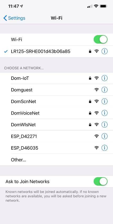
2. Open your device settings and search for available Network Page.
Wi-Fi networks.
3. Locate and connect to the Wi-Fi network named
LR-125.
43 Network Configuration Menu
42 Wi-Fi Networks The following screen appears, where you can update
your password as desired.
4. Enter the default password, which is
YourPassPhrase.
You should now be successfully connected to Dometic
Interact. You can proceed to change the password
settings, if desired.
EN 25Operation Dometic Interact
• SSID: The default SSID and user name for this multiplex
system will look similar to “LR125-xxxxxx” (xxxxxx =
serial number). You may also customize the SSID.
5. After your password and WiFi settings are updated,
restart your Wi-Fi server and log in with the new
credentials.
4.2.4 Navigation and Use
After successful connection to the Dometic Interact Wi-Fi
network, you are ready to begin using your mobile device
to control the available components within your control
configuration.
The mobile application landing page includes the
following navigation options:
44 Network Configuration Update Menu
I Your new password must be at least eight characters
(and include letters, number, or combination) to
avoid a lockout scenario. 45 Landing Page Navigation
If the original password you use to make the update From the landing page, you can tap the following tabs to
is less than eight characters, the application will reach the desired screen:
accept it. However, the application will not allow
you to log in later with an invalid password. You • Main Screen: Tap this tab to reach the Main
would have to reset the Wi-Fi module. Using an eight Navigation screen. Once you reach the Main
or more character password should avoid this Navigation screen, you can navigate to and use the
lockout situation. main screens just as described in the Touch-Screen
Navigation and Use section.
4. Update your password settings.
• Wireless mode: This option allows you to define the
wireless mode.
– Access Point: The Wi-Fi server module will act as an
access point, so that the other personal mobile
devices will connect to it directly.
– Infrastructure: The Wi-Fi server module will be
connected through any other Wi-Fi device or
modem, such as Winegard.
26 ENDometic Interact Maintenance
• System Configuration: Tap this tab to reach the • View Log: Tap this tab to reach the LR 125 Boot Log
System Configuration screen, where you can elect to screen, where you can choose to load the boot log for
show metric values, or enable the splash screen. the Wi-Fi server.
46 System Configuration Screen
48 Boot Log Screen
• Update Software: Tap this tab to reach the Update
WiFi Server Software screen, where you can view and • Close: Tap this tab to close the mobile application.
manage the current software versions.
5 Maintenance
! WARNING: FIRE AND/OR ELECTRICAL SHOCK
HAZARD
Use care when diagnosing, repairing, adjusting,
and/or cleaning components on a powered unit.
Failure to obey this warning could result in death or
serious injury.
This section describes how to care for and maintain
Dometic Interact. Refer to the following sections for
information about care, cleaning, and preventive
maintenance of the product.
5.1 Care and Cleaning
! WARNING: FIRE AND/OR SHOCK HAZARD.
Do not allow water to splash on or pour into a
powered unit. Failure to obey this warning could
result in death or serious injury.
47 Update WiFi Server Software Screen
EN 27Troubleshooting Dometic Interact
NOTICE: Do not use abrasive cleaning materials or 6 Troubleshooting
harsh chemicals on the touch-screen display, or damage
to the product can occur.
! WARNING: FIRE AND/OR ELECTRICAL SHOCK
If the touch-screen display becomes dirty, clean it with a HAZARD
soft, dry cloth, or use compressed air to loosen debris Use care when diagnosing, repairing, adjusting,
from the external orifices. and/or cleaning components on a powered unit.
Failure to obey this warning could result in death or
To remove hard dirt or grime, a slightly damp cloth with
serious injury.
non-abrasive cleaning product is acceptable; however,
take care not to damage the touch-screen display. This section describes how to troubleshoot common
errors that may be encountered on Dometic Interact.
5.2 Preventive Maintenance
I Refer to your inverter operating manual for
troubleshooting information and to obtain customer
Use the following tips to ensure that your control service center information. Contact the
continues to work properly: manufacturer customer service department for
• Ensure that the touch-screen display and PCB are inverter-related issues.
operated between -4 °F to 140 °F (-20 °C to 60 °C). The table that follows describes some common errors
• Ensure that you power on the control system that may be encountered with the control, their possible
occasionally during extended periods of non-use. causes, and the recommended corrective actions.
Contact Dometic Customer Support Center at
1-800-544-4881, or email
customersupportcenter@dometic.com for any other
assistance.
Error Possible Cause Recommended Corrective Action
There is power loss to Dometic There is too much load on the circuit. Turn off the battery switch near the entry steps. Wait 10
Interact. seconds, and turn the battery switch on.
The screen does not wake up. You are not within range of the display Move closer to the LCD screen, or tap it once to turn it
proximity sensor. on.
The coach lights are not turning There is a blown software fuse, or the Examine the Dometic Interact Fuses screen and reset
on. LED light needs to be replaced. the blown fuse, or replace the LED bulb.
Recycle the power through the battery switch at the
entry way.
The AC will not turn on or off. The AC is in a time-delayed start up, or The AC can take up to three minutes to respond to on/
the AC circuit breaker has tripped. off commands.
Reset the circuit breaker, if needed.
You are unable to locate or You are not within range of the LR-125 Seek a stronger Wi-Fi signal.
connect to the LR-125 Wi-Fi Wi-Fi module. There is no Wi-Fi Contact the Dometic Customer Support Center to
server. connection or the connection has been reset the modem.
lost.
There is a water pump failure. There is a blown software fuse. Examine the Dometic Interact Fuses screen and reset
the blown fuse, if applicable.
There is a satellite dish failure. There is a blown software fuse, or the Examine the Dometic Interact Fuses screen and reset
satellite dish is disabled. the blown fuse, or enable the satellite dish in the
Settings screen.
28 ENDometic Interact Disposal
Error Possible Cause Recommended Corrective Action
The touch-screen is The system might be frozen. Reboot the system by interrupting the power supply
unresponsive. for ten seconds.
There is audio trouble. The audio level is set too low. Adjust the audio level in the Settings screen, and
reboot the system.
The tank level readings are The RV is not level or stationary. Bring the RV to a complete stop and ensure that it is
inaccurate. level.
The generator fails to exercise. The AGS is turned off, the ignition safety Turn on the AGS, remove the key from the vehicle
interlock is enabled, or the settings are ignition, or adjust the time settings.
incorrect. Go to Power screen and press the CLEAR AGS button
An external activity such as a quiet time on the bottom of the screen.
or a manual shut off has occurred.
The vent fan will not operate. The lid is stuck in the closed position. Check the lid and use the manual switch to open or
The vent fan fuse may have blown. loosen the lid.
Replace the 4 A fuse on the vent fan.
The Climate screen Inside and A sensor is not connected properly. Check the sensor connections for damaged or
Outside temperature The temperature is outside of the loose wires.
indicators display “- - “ sensor temperature range [< -100 or Check the temperature indicator again when the
> 200 °F (< -73 or > 93 °C )]. outside temperature is within sensor range.
If the screen still displays incorrectly, replace the
sensor.
7 Disposal
Place the packaging material in the appropriate
M recycling waste bins, whenever possible. Consult a
local recycling center or specialist dealer for details
about how to dispose of the product in accordance
with all applicable national and local regulations.
LIMITED ONE-YEAR WARRANTY
LIMITED ONE-YEAR WARRANTY AVAILABLE AT
WWW.DOMETIC.COM/WARRANTY.
IF YOU HAVE QUESTIONS, OR TO OBTAIN A COPY OF
THE LIMITED WARRANTY FREE OF CHARGE, CONTACT:
DOMETIC CORPORATION
CUSTOMER SUPPORT CENTER
5155 VERDANT DRIVE
ELKHART, INDIANA, USA 46516
1-800-544-4881 OPT 1
EN 29Contenu Dometic Interact
Liste des centres de service et des revendeurs
Visiter : www.dometic.com
Lire attentivement ces instructions. Ces instructions DOIVENT rester avec ce produit.
Contenu
4.1.13 Écran Bathroom (Salle de bain) . . . . . . 54
1 Explication des symboles et 4.1.14 Écran Entry (Entrées) . . . . . . . . . . . . . . 55
des consignes de sécurité . . . . . . . . . . . . . . . . . 31 4.1.15 Écran Clock (Horloge) . . . . . . . . . . . . . 55
1.1 Reconnaître les consignes de sécurité . . . . . . . 31 4.1.16 Écran Notifications. . . . . . . . . . . . . . . . 56
1.2 Comprendre les mots-indicateurs. . . . . . . . . . . 31 4.2 Navigation et utilisation des applications mobiles
1.3 Directives supplémentaires . . . . . . . . . . . . . . . . 31 57
1.4 Messages de sécurité d’ordre général . . . . . . . 31 4.2.1 Conditions préalables . . . . . . . . . . . . . 57
4.2.2 Première connexion . . . . . . . . . . . . . . 57
2 Informations générales . . . . . . . . . . . . . . . . . . 32
4.2.3 Paramètres du mot de passe et du SSID. .
2.1 Caractéristiques principales . . . . . . . . . . . . . . 32
58
3 Indication . . . . . . . . . . . . . . . . . . . . . . . . . . . . . 32 4.2.4 Navigation et utilisation. . . . . . . . . . . . 59
4 Fonctionnement . . . . . . . . . . . . . . . . . . . . . . . . 33 5 Maintenance . . . . . . . . . . . . . . . . . . . . . . . . . . . 60
4.1 Navigation et utilisation de l’écran tactile . . . . 33 5.1 Entretien et nettoyage . . . . . . . . . . . . . . . . . . . .61
4.1.1 Écran de navigation principal et icônes33 5.2 Maintenance préventive . . . . . . . . . . . . . . . . . .61
4.1.2 Écrans Climate (Climat) . . . . . . . . . . . . 34
6 Dépannage . . . . . . . . . . . . . . . . . . . . . . . . . . . . . 61
4.1.3 Écrans Scheduler (Planificateur) . . . . . 36
7 Mise au rebut . . . . . . . . . . . . . . . . . . . . . . . . . . 62
4.1.4 Écran Mechanical (Mécanique) . . . . . 37
4.1.5 Écran Lights (Lumières) . . . . . . . . . . . . 38 GARANTIE LIMITÉE DE UN AN . . . . . . . . . . . . . . . 62
4.1.6 Écran Power (Alimentation). . . . . . . . . 39
4.1.7 Écran AGS . . . . . . . . . . . . . . . . . . . . . . 44
4.1.8 Écran Tanks (Réservoirs) . . . . . . . . . . . 46
4.1.9 Écran Settings (Paramètres) . . . . . . . . 48
4.1.10 Écran Programs (Programmes) . . . . . . 52
4.1.11 Écran Fuses (Fusibles) . . . . . . . . . . . . . 53
4.1.12 Écran Bedroom (Chambre) . . . . . . . . . 54
30 FRYou can also read