DIGITAL RAILWAY - SYSTEM OF SYSTEMS (SOS) SYSTEM DEFINITION
←
→
Page content transcription
If your browser does not render page correctly, please read the page content below
Reference       153821-NWR-REP-ESE-000002
                    Issue/Ver:      4.0
                    Date:           27th April 2018

       Digital Railway – System of
       Systems (SoS) System
       Definition

Prepared By
David Nicholson
Systems Integration & Interface Manager

DJN-270418-0006                  Date: 27th April 2018

Reviewed By
Tracey Best
Head of Systems Engineering

TLB-270418-0026                  Date: 27th April 2018

Accepted By
Anders Møller
Head of System Requirements & Integration

ANDM-270418-0028                 Date: 27th April 2018
Reference     153821-NWR-REP-ESE-000002
                                                                Issue/Ver:    4.0
                                                                Date:         27th April 2018

Electronic file reference: https://digitalrailway.ipss-
                           hdms.co.uk/DigitalRail/Framework/Object.aspx?o=1079&t=3

Disclaimer
Group Digital Railway has used its best endeavours to ensure that the content, layout and text of this
document are accurate, complete and suitable for its stated purpose. It makes no warranties,
expressed or implied, that compliance with the contents of this document shall be sufficient to ensure
safe systems of work or operation. Group Digital Railway will not be liable to pay compensation in
respect of the content or subsequent use of this document for any purpose other than its stated
purpose or for any purpose other than that for which it was prepared except where it can be shown to
have acted in bad faith or there has been wilful default.

© Copyright 2018 Group Digital Railway.
This document is the property of Group Digital Railway. It shall not be reproduced in whole or in part,
not disclosed to a third party, without the written permission of Group Digital Railway.

Document owner:                  David Nicholson, Systems Integration & Interface Manager

Version History

Issue          Date            Comments
1.0            29.05.17        First issue
2.0            1.11.2017       Minor updates and final issue.
2.1            30.01.2018      Update to align with new strategy [RI10]
2.2            23.02.2018      Update after internal review.
3.0            05.03.2018      Updated after review and comments close out.
                               Updates to reflect received AsBo comments, references and minor
3.1            25.04.2018
                               clarifications.
4.0            27.04.2018      Issued for signature.

Exclusions
These are items currently missing from this version of the document that should be included in a later
publication.
      1. Best endeavours have been used during the development of this specification to align it to the
         relevant Concepts of Operations documents which have been updated in parallel. Final
         assurance of the complete alignment of this specification with the relevant industry-endorsed
         Concepts of Operations will be achieved in a later version.

Assumptions
These are items upon which the validity of this document relies and will be delivered by others. Non-
delivery of these items will necessitate a change to this document.
      2. None.

                                                                                          Page 2 of 43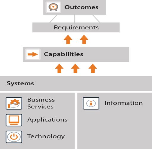
Reference    153821-NWR-REP-ESE-000002
                                                           Issue/Ver:   4.0
                                                           Date:        27th April 2018

Dependencies
These are items upon which the validity of this document depends. Any changes to the dependencies
document may require further changes to this document.
   1. Comments have been received from the AsBo on v3.0 of this System Definition
      document[RD6]. No category 1 comments have been received (meaning an update is
      necessary). Remaining open comments will be addressed in a future review of this document.

                                                                                    Page 3 of 43
Reference 153821-NWR-REP-ESE-000002
Issue/Ver: 4.0
Date: 27th April 2018
Contents
Abbreviations .......................................................................................................................................... 7
References .............................................................................................................................................. 8
1 Introduction ...................................................................................................................................... 9
1.1 Background ............................................................................................................................. 9
1.2 The Digital Railway Programme (DRP) .................................................................................. 9
1.3 Context & Purpose of this Document ...................................................................................... 9
1.4 Scope .................................................................................................................................... 10
1.5 Generic System of Systems (SoS)........................................................................................ 10
1.6 Document Maintenance ........................................................................................................ 11
2 System Purpose and Objectives .................................................................................................... 13
3 Overall Programme Capabilities .................................................................................................... 15
4 System of System Functions and Elements .................................................................................. 17
4.1 DR System of System Operation .......................................................................................... 17
4.1.1 System of System Functions ............................................................................................. 18
4.1.2 Normal operation ............................................................................................................... 19
4.1.3 Degraded mode operation ................................................................................................ 20
4.1.4 Emergency mode operation .............................................................................................. 21
4.2 Digital Railway Technologies ................................................................................................ 21
4.2.1 Traffic Management .......................................................................................................... 21
4.2.2 European Train Control System (ETCS) Trackside .......................................................... 22
4.2.3 European Train Control System (ETCS) Onboard ............................................................ 23
4.2.4 Connected-Driver Advisory System .................................................................................. 23
4.2.5 Business Continuity ........................................................................................................... 23
4.2.6 Operational Readiness ...................................................................................................... 23
4.2.7 Data ................................................................................................................................... 24
4.2.8 Training inc. Simulator ...................................................................................................... 24
4.2.9 SoS Deployment Guide ..................................................................................................... 24
4.3 Enabling Projects: ................................................................................................................. 24
4.3.1 Signal-Controlled Warning System (SCWS) ..................................................................... 24
4.3.2 Key Management System ................................................................................................. 25
4.3.3 Customer Information System (CIS) ................................................................................. 25
4.3.4 Stock & Crew System ....................................................................................................... 25
4.3.5 Incident Management System ........................................................................................... 25
4.3.6 Capacity Planning / Timetable Planning ........................................................................... 26
4.3.7 Other Comms: Wireline Comms (FTN(X)) & Wireless Comms (GSM-R) ......................... 26
4.3.8 Layered Information eXchange (LINX) ............................................................................. 26
4.3.9 EULYNX ............................................................................................................................ 26
Page 4 of 43Reference 153821-NWR-REP-ESE-000002
Issue/Ver: 4.0
Date: 27th April 2018
4.3.10 Business Systems Development................................................................................... 26
5 System Boundary........................................................................................................................... 28
6 Physical Interfaces ......................................................................................................................... 29
6.1 ROC ...................................................................................................................................... 29
6.1.1 Building Interior ................................................................................................................. 29
6.1.2 Power Supply .................................................................................................................... 29
6.2 Data Centre ........................................................................................................................... 29
6.3 Telecommunications ............................................................................................................. 29
6.3.1 LAN ................................................................................................................................... 29
6.3.2 FTN / FTN-X ...................................................................................................................... 29
6.3.3 GSM-R .............................................................................................................................. 29
6.3.3.1 Data ........................................................................................................................................ 29
6.3.3.2 Voice ...................................................................................................................................... 30
6.3.4 Third-Party Data Network .................................................................................................. 30
6.4 Trackside ............................................................................................................................... 30
6.4.1 MAS ................................................................................................................................... 30
6.4.2 Train Detection .................................................................................................................. 30
6.4.3 AWS/TPWS ....................................................................................................................... 30
6.5 Rolling Stock ......................................................................................................................... 30
6.6 Other physical interfaces ....................................................................................................... 31
7 Functional Interfaces...................................................................................................................... 32
7.1 Staff ....................................................................................................................................... 32
7.1.1 Operational & Maintenance Staff ...................................................................................... 32
7.1.2 Operations Staff ................................................................................................................ 32
7.1.3 TOC station staff ............................................................................................................... 32
7.1.4 Trackside Staff .................................................................................................................. 32
7.1.5 Drivers ............................................................................................................................... 32
7.1.6 Incident Investigators ........................................................................................................ 33
7.1.7 Remote Users, TOCs & FOCs .......................................................................................... 33
7.2 Command, Control and Signalling Systems ......................................................................... 33
7.2.1 Adjacent Control Systems ................................................................................................. 33
7.2.2 Operational Telecoms ....................................................................................................... 33
7.2.3 Signalling and Train Control Systems ............................................................................... 33
7.2.4 Level Crossings ................................................................................................................. 33
7.3 Equipment Monitoring Systems ............................................................................................ 34
7.3.1 Traction Supply Control ..................................................................................................... 34
7.3.2 Infrastructure Monitoring Systems .................................................................................... 34
7.3.3 Vehicle Monitoring Systems .............................................................................................. 34
7.4 Management Systems .......................................................................................................... 34
Page 5 of 43Reference 153821-NWR-REP-ESE-000002
Issue/Ver: 4.0
Date: 27th April 2018
7.4.1 Decision Support Tools ..................................................................................................... 34
7.4.2 Planning, Information & Management Systems ................................................................ 34
7.4.3 Data Management Capability ............................................................................................ 35
7.4.4 External (Third Party) Systems ......................................................................................... 35
7.5 Rolling Stock ......................................................................................................................... 35
7.6 Business Systems ................................................................................................................. 36
8 System Environment ...................................................................................................................... 37
8.1 Procedures and Rules ........................................................................................................... 37
8.2 Staff Competence and Assessment ...................................................................................... 37
8.3 Security ................................................................................................................................. 37
8.4 Maintenance .......................................................................................................................... 37
8.5 Local Environment and Conditions ....................................................................................... 38
8.5.1 Line-side ............................................................................................................................ 38
8.5.2 On-board ........................................................................................................................... 38
8.5.3 Trackside ........................................................................................................................... 38
8.6 Electro-Magnetic Compatibility (EMC) .................................................................................. 38
8.7 Human Factors ...................................................................................................................... 38
8.8 TOC & FOC ........................................................................................................................... 38
9 Existing Safety Measures .............................................................................................................. 39
10 Assumptions .............................................................................................................................. 40
Interfaces & Messaging ................................................................................................. 41
Page 6 of 43Reference 153821-NWR-REP-ESE-000002
Issue/Ver: 4.0
Date: 27th April 2018
ABBREVIATIONS
Abbreviations and acronyms are contained within the DR Glossary of Terms and
Abbreviations [RD8]. They are also explained on first use.
Page 7 of 43Reference 153821-NWR-REP-ESE-000002
Issue/Ver: 4.0
Date: 27th April 2018
REFERENCES
Dependant References
An update to one of these references requires an update to this document:
RD1. Digital Railway Programme – Vision, Purpose, Objectives 000000-NWR-PLN-
MAN-000001, v1.0
RD2. The Common Safety Method for Risk Evaluation and Assessment (CSM RA)
regulation, Commission Regulation (EU) 402/2013, 30th April 2013
RD3. The Common Safety Method for Risk Evaluation and Assessment (CSM RA)
regulation amendment, Commission Regulation (EU) 2015/1136, 13th July 2015
RD4. Digital Railway – M9 Significance of Change Assessment, 147833-NWR-ASS-
ESS-000001, Ver.0.1, 6th November 2017
RD5. Commission Regulation (EU) 2016/919, 27th May 2016
RD6. Assessment Record No.2 – Digital Railway System of Systems (SoS) System
Definition, 153819-NWR-COM-ESE-000001, Issue 3.0, 23rd March 2018
RD7. Digital Railway Programme –Interface Description Document, 153819-NWR-
RCD-ESE-000001, Version 4.0
RD8. Digital Railway – Glossary of Terms and Abbreviaions, 153819-NWR-SPE-ESE-
000001, Issue 1.0, 15th February 2018
Informative References
These references have no material bearing on the content of this document:
RI1. Digital Railway Ready Signalling Specification, DRD-NONE-TAD-147866-SPE-
160727-125430, Version 2.1, 5/12/2016
RI2. Network Rail – Security Assurance Framework – Procedures, NRT/SY/2015/036,
Ver.2.3, 15 July 2016.
RI3. DR Railway Capability Definition, no reference, draft 0.1, 19/05/2016
RI4. ETCS Baseline 3 GB Onboard Retrofit Subsystem Requirements Specification
(EOSS), NEPT/ERTMS/REQ/0007, Rev.3.0, 31st March 2017
RI5. ETCS Baseline 3 GB Onboard New Trains Subsystem Requirements
Specification (ENTOSS), NEPT/ERTMS/REQ/0038, Rev.2.0, 31st March 2017
RI6. Digital Railway Migration State M9 Concept of Operations,
DRD/00000/DRP2/SPE/100031, Issue 2.0, 12/07/2017
RI7. DR Level A, Generic Hazard Record, DRD-PH2-NONE-TAD-147833-CSM2-
161005-180625, Draft B3, 9/03/2017
RI8. DR System Safety Plan, 147833-NWR-PLN-MPM-000008, Rev.02, 11th October
2017.
RI9. DR Project RAID log, no reference No, Version 1.0, 16/12/2013
RI10. Digital Railway – System of Systems Realignment Strategy, 153819-NWR-STR-
SSD-000001, v1.0, 27th November 2017
RI11. Commission Regulation (EU) 2016/919, CCS TSI (as amended)
RI12. Digital Railway, Capability Maturity Model and Programme Capability Report,
DRD-PH3-MSP2-TAD-000000-DEL-160503-182456, v1.1, 3rd May 2016
Page 8 of 43Reference 153821-NWR-REP-ESE-000002
Issue/Ver: 4.0
Date: 27th April 2018
1 INTRODUCTION
1.1 Background
Digital Railway is a rail industry-wide programme designed to benefit Great Britain’s
economy through more effective train operation, customer experience and industry
adaptability, enabled by accelerating the application of digital technologies to the railway.
The benefits of the Digital Railway are expressed as:
• More trains
• Better connections
• Improved reliability
These are to be delivered by the Digital Railway Programme to GB Rail through the
application of modern train control technology. The vision, purpose and objectives have
been summarised as [RD1]:
• Increased capacity
• Safer, more secure & environmental railway
• Improved train performance (reliability and availability)
• Improved whole life cost and sustainable commercial model
• Wider socio-economic benefits (e.g. skills, productivity, housing, exports)
This is an industry-wide programme involving Network Rail (as Infrastructure Manager),
Train and Freight Operating Companies (as Railway Undertakings), RSSB, Yellow plant
and the supply chain. It will also engage with the Regulator and the Department for
Transport (DfT) as necessary to secure the required improvements to safety and
customer provision, funding and approvals.
1.2 The Digital Railway Programme (DRP)
The Digital Railway Programme has several principal outcomes. These are:
1. Creation of a generic customer requirements for deploying Digital Railway (DR)
Systems (using European Train Control System (ETCS) Level 2, Traffic
Management (TM) and for interfaces with other systems and enablers).
2. Preparation of business cases that provide input to Route strategic business
plans for deployment projects using specific applications of DR Systems.
3. Assisting deployment projects to deploy specific DR Systems as a result of the
Business Plan work undertaken in 2 above.
4. Production of guidance notes, rules, processes and templates to help
deployment projects. Where remitted, DR will provide support to deployment
projects in determining the deltas between the DR System of Systems (SoS)
items and their particular deployment.
In the context of the DR Programme, the term ‘System’ refers to the various digital
technologies to be deployed (i.e. European Train Control System (ETCS) Level 2, Traffic
Management (TM), C-DAS and other systems and enablers).
System of Systems (SoS) refers to their integration in a baseline architecture to enable
the full benefits of the digital technologies to be realised.
Both terms include more than just the systems themselves, but also the people,
processes and data required to enable operation.
Within the DR Programme, the System Requirements and Integration (SR&I) team is
charged with producing the outputs required under items 1 and 4 above.
1.3 Context & Purpose of this Document
An EU Regulation on the adoption of a Common Safety Method (CSM) on risk evaluation
and assessment (CSM RA) came into full effect through Regulation 402/2013 [RD2] and
amended by Regulation 2015/1136 [RD3] in August 2015. The CSM RA applies when
any technical, operational or organisational change is being proposed to an operational
Page 9 of 43Reference 153821-NWR-REP-ESE-000002
Issue/Ver: 4.0
Date: 27th April 2018
railway. The Digital Railway Programme considered as a whole will bring complex
technical changes to the rail infrastructure resulting in a significance impact on the
operation and organisation of GB rail. A formal assessment of the significance of the
change has been undertaken [RD4] and concluded that the change is significant with
high uncertainty and high consequence.
A key component of the hazard identification and risk assessment process defined in the
CSM Regulations is the preparation of a System Definition i.e. this document. The
purpose of the System Definition document under CSM RA is to complement the hazard
record by bounding the scope of the hazard identification and risk assessment process
and provide sufficient context to facilitate an assessment of the correct application of the
process by an independent body (the Assessment Body, or AsBo).
Due to the industry wide nature of DR, it is also an essential requirement that the DR
programme clearly defines what is meant by ‘System of Systems’ and ‘System’ and its
interfaces to ensure successful requirements apportionment. This will result in minimizing
integration risk during deployment. This System Definition document will fulfil that need
of defining the system, its interfaces and thus minimize integration risks.
The System Definition defines the key details of the baseline System of Systems, its
purpose, functions, interfaces and the existing safety measures that apply to it, so that it
provides a generic design in support of subsequent development and deployment (i.e.
application-specific design and implementation). It also allows the generic specification
and design for the SoS and Systems to be assessed in accordance with the CSM RA in
order to provide a basis for a safety case and the associated business change,
operational rules and processes to be developed to support it too.
This document has been written to support a high-level understanding of the DR SoS,
and is also intended to support the early stages of hazard analysis of the proposed
solution.
1.4 Scope
This document applies to the outputs of the SR&I team only as listed in section 1.2
above.
This generic requirements only consider the deployment of the core Systems as a SoS
and does not consider how a particular section of the railway might operate if only some
of the systems are deployed. Any variation from a full deployment will need to be
addressed by the particular Route (i.e. Infrastructure Manager and Railway
Undertakings) concerned.
This document does not apply to a specific deployment of the core Systems; it deals with
the generic SoS design and its associated interfaces (both physical and non-physical
(e.g. operators)).
This document does not describe in detail the Systems upon which it is dependent (e.g.
ETCS, TM and C-DAS) as these will have their own System Definitions.
1.5 Generic System of Systems (SoS)
The SR&I team will deliver a set of GB rail specifications for system development and
integration purposes using a common baseline architecture referred to as the System of
Systems (SoS).
This SoS provides a modern integrated railway signalling command and control system
based on:
• ETCS Trackside, incorporating equipment trackside for Level 2 (no signals),
modern interlocking technologies, and trackside equipment necessary for fitted
trains running elsewhere on the GB rail network
Page 10 of 43Reference 153821-NWR-REP-ESE-000002
Issue/Ver: 4.0
Date: 27th April 2018
• ETCS Onboard1
• Traffic Management
• Connected-Driver Advisory System (C-DAS)
The SoS will be supported by:
• A fixed data network, e.g. the Fixed Telecoms Network (FTN) or the FTN – next
generation (FTNx)
• A voice and data communications network
• Data services, systems and protocols and Key Management
• Operational readiness to support the people and process change required
The SoS configuration ensures that the systems within it, e.g. the European Train
Control System (ETCS), Traffic Management (TM) etc, can be developed by the supply
chain with the majority of the interfaces built in to minimise future integration and
migration costs for deployment programmes.
The SoS configuration will be supported by the production of a series of guidance notes,
rules, processes and templates to help a specific delivery project to deploy DR Systems.
1.6 Document Maintenance
This System Definition Document is owned by the Systems Integration & Interface
Manager. It will be subject to review at least prior to any required stage gate to ensure its
ongoing adequacy for progressing to any future stage gate. Other updates may be
instigated as necessary when directed by the Head of Systems Engineering.
This document has presumed a particular baseline technical solution as outlined in the
Realignment Strategy [RI10]. However, if during delivery of this plan, a different technical
solution comes to light that would also achieve the Digital Railway primary objectives
(see section 2), then these will be considered. An update to this document may then be
necessary.
This System Definition will be updated during this programme to reflect the evolving
stages of development and a final update will include the safety requirements identified
from the hazard identification (HAZID) to form an accurate and final representation of the
System of Systems.
An update to this document will also arise as details of the generic design become clear.
This includes the application of data and allocation of Safety Integrity Levels (SILs) to
particular functions.
The application of DR Systems to a specific section of railway is outside the scope of this
System Definition document. Specific applications will be addressed through a
deployment-specific System Definition document.
1 It should be noted the Control-Command Signalling (CCS) Technical Specification for
Interoperability (TSI) [RI11] requires that the onboard elements of ETCS supports all
ETCS levels, not just Level 2.
Page 11 of 43Reference 153821-NWR-REP-ESE-000002
Issue/Ver: 4.0
Date: 27th April 2018
Page 12 of 43Reference 153821-NWR-REP-ESE-000002
Issue/Ver: 4.0
Date: 27th April 2018
2 SYSTEM PURPOSE AND OBJECTIVES
The principal objectives of the DR SoS generic design are to:
• Result in successfully deploying an integrated and repeatable train command,
control and safety system on GB rail to deliver the objectives mentioned in 1.2
which includes:
o Traffic Management System;
o Connected-Driver Advisory System;
o ETCS Trackside, incorporating equipment trackside for Level 2 (no
signals), modern interlocking technologies, and trackside equipment
necessary for fitted trains running elsewhere on the GB rail network
o ETCS Onboard1
• Provide the framework to enable delivery of the Digital Railway Vision and to
ensure that all DR delivery activities are aligned against a common
understanding and baseline architecture (i.e. maintenance, operations,
engineering, people and process etc);
• Provide a foundation for enabling the systems to be configured;
• Automated control of train paths derived from a planned time-table;
• The safe movement of rolling stock;
• An enhanced safety environment for workers on or about the running lines;
• Increased service reliability and the potential for increased capacity and
performance (subject to the specifics of the deployment);
• Secure transmission of command-control information (i.e. KMS).
To ensure that any future deployment is successful, business change activities (e.g.
people and process change) will also be required to support optimal operation of the
systems and to maximise benefits gained.
After the creation of Customer Requirement Specifications (CRSs), application-specific
requirements would need to be created so that the DR technologies could be applied to
the specific route. Following this, there may be a supply chain development and
integration stage for the systems concerned (e.g. TM, ETCS and C-DAS) and the use of
test facilities (e.g. suppliers’ own test facilities, ERTMS National Integration Facility
(ENIF) and Railway Innovation and Development Centre (RIDC)), prior to actual
deployment on the operational railway.
This System Definition (and architecture) is route and solution agnostic, however it is
based around current and emerging technology solutions. The system architecture
shown in Figure 1 represents the Digital Railway SoS functional architecture. The
diagram shows the Infrastructure and Rolling Stock Systems and their functional
interrelationships.
Generic roles that are integral to the SoS architecture are presented, but these are
currently shown in grey as the interfaces between these roles and the Systems are still to
be defined. Similarly, interfaces for the Infrastructure and On-board data hub have been
omitted pending their development and review by subject matter experts. The
architecture is not intended to be read as a physical relationship diagram. A number of
Enhancing Facilities and Required Enablers are shown where these directly enable or
interface to one of the DR Systems.
Further details of the interfaces shown (including protocol, bearer and multiplicity) and
the information flowing over them are covered in the document Digital Railway
Programme Interface Description Document [Ref RD7].
Page 13 of 43Reference 153821-NWR-REP-ESE-000002
Issue/Ver: 4.0
Date: 27th April 2018
Figure 1 –DR System of Systems architecture
Page 14 of 43Reference 153821-NWR-REP-ESE-000002
Issue/Ver: 4.0
Date: 27th April 2018
3 OVERALL PROGRAMME CAPABILITIES
Early work undertaken by the Digital Railway Programme [RI12] identified 11 outcomes
that it could deliver. This further identified a set of capabilities for the industry that
delivered against the 11 outcomes, that the System of Systems (including the associated
Operations, Business Change etc.) will be required to deliver, as shown in the following
diagram:
Figure 2 – The Enterprise Architecture Hierarchy
The capabilities provided for information only in Table 1 below represent the ideal end
state of the Digital Railway Programme. The capabilities are not exclusively supported
by DR technologies; other DR work streams such as operations, business change,
maintenance and safety will integrate to support the delivery of these capabilities.
The SoS will be defined in terms of a sub-set of the overall DR programme capabilities,
[RI3]. This approach will ensure that there is a common foundation for the deployment of
DR Systems and the evolution of them (e.g. from ETCS Level 2 to Level 3) and that
transition between the two is made easier.
This work is being undertaken through an Enterprise Architecture model and is still being
refined.
Table 1 - DR Programme Capabilities
No. Capability Group Definition
Leading and guiding the industry and associated
organisations from funds acquisition to
1 Industry Management
performance and benefit realisation, allowing for
a competitive and differentiated market place.
Providing core industry back-office services
including financial, Human Resources (HR) and
2 Industry Administration
Information & Communications Technology
(ICT) management.
Page 15 of 43Reference 153821-NWR-REP-ESE-000002
Issue/Ver: 4.0
Date: 27th April 2018
Managing the relationship and communications
Stakeholder with all stakeholders including Europe,
3 Relationship government, regulators, customers and
Management suppliers (covering internal and external
communications).
Ensuring compliance with statutory and
Industry Compliance
4 regulatory directives and promoting industry
and Citizenship
good-citizenship.
Planning and managing the acquisition, storage
5 Logistics Management and movement of materials between the point of
origin to the point of consumption.
Managing the operational use and commercial
6 Property Management
exploitation of property.
Capturing, managing and providing controlled
Industry Information
7 access to industry information to support
Management
internal and external stakeholder needs.
Delivering the timetable on the day, covering
Service Delivery
8 both the scheduled train service, and managing
Management
incidents / disruption.
9 Capacity Management The matching of journey supply to demand
Managing the railway system from acquisition
Rail Systems Lifecycle
10 through to disposal, condition management,
Management
maintenance, renewal and enhancements.
Managing the services required to provide a
11 Journey Management
journey
User Expectation Recording and managing customer journey
12
Management expectations
Customer Identity
13 Managing customers personal information
Management
Page 16 of 43Reference 153821-NWR-REP-ESE-000002
Issue/Ver: 4.0
Date: 27th April 2018
4 SYSTEM OF SYSTEM FUNCTIONS AND ELEMENTS
This section provides an outline of the SoS operations and systems and the enablers
required to support future deployment of the SoS on GB Rail.
The following are considered essential SoS elements to support deployment:
• Traffic Management (TM), ETCS Trackside, ETCS Onboard and C-DAS
• Operational Readiness
• Enabling Projects (e.g. GSM-R upgrade, National KMS)
In addition to these elements, described in detail in the following sections – there will be
a need for the industry to develop the following to realize the full potential of deploying
Digital Railway Systems:
• Configuration data: At each location where DR Systems are deployed, there
will be site specific configuration data (e.g. geographic, functional, etc.) that will
define how that specific DR System interacts with the railway it controls and the
site-specific functions it applies.
It is expected that there will be a Test Yard (i.e. an example of a typical track
layout) that will be used as a test bed as part of a deployment’s system
development and integration activities (e.g. at ENIF and supplier’s own facilities)
and this will require configuration data.
• Maintenance Procedures: The new functionality provided by the Digital Railway
Systems will require revised maintenance procedures for areas of the railway
where the DR Systems are deployed and any transitional arrangements that may
be required where new and old technology exists.
• Operator Manuals: Manuals will contain comprehensive material that supports
new and existing skill sets and will define the tasks that operational and
maintenance staff will carry out on the various the Systems and on the SoS as a
whole.
• Maintenance tools: DR Systems will assist maintainers in predicting and
identifying faults. Maintenance tools will enable maintainers to predict, identify
and rectify faults in the various DR Systems. An assessment on the maintenance
impact of all the component parts is to be undertaken and national/industry level
ownership and definition is to be defined.
• Training material: Training material will enable operational and maintenance
staff to learn and practice the tasks that they will be required to carry out in their
role before they do this on a live system. Typical training material includes
simulators, videos, presentations and course notes.
4.1 DR System of System Operation
The DR Concept of Operations [Ref RI6] and the subsidiary Concepts of Operations
produced for the individual DR Systems will provide greater detail on the SoS operation.
However, this section is included to provide a brief summary of how the DR SoS typically
operates to aid understanding of other sections of this document.
The DR SoS will support operation in normal, degraded and emergency modes, although
the latter two will depend on the cause and scale of the degraded or emergency mode of
operation. Regardless of mode, the systems, supported by processes and rules, will
ensure adherence to the four fundamental signalling principles of:
• Safe Spacing: A train is given a route that is clear of other trains;
• No Excess Speed: A train will operate within the speed limits currently in force
for the route and train;
• Route Holding: The route, once given to the train, is not revoked or altered
without some form of assurance that the train is not to make use of that route;
• No conflicting moves: The route offered to a train is clear of any other route
offered to other trains
The following sections describe the functions provided by the SoS, and then describe
operations in normal, degraded and emergency modes.
Page 17 of 43Reference 153821-NWR-REP-ESE-000002
Issue/Ver: 4.0
Date: 27th April 2018
4.1.1 System of System Functions
The SoS functions 2 being delivered are listed below (additional functions may yet be
identified):
• Provide information to planning: DR provides appropriate information to allow
the central timetable process to take into account DR technologies. To meet the
required outcomes and performance e.g. increased capacity and reduced
journey times, DR technologies are employed. Includes improved train
performance characteristics and changes to train operation.
• Operate the network to the current plan: Requests that routes are set in the
correct order and at the correct time to allow trains to move across the network
safely in order to fulfil the current plan.
• Safely command a train: Following the receipt of a control request, this
performs the appropriate network operation(s) to allow safe train movements.
This provides an appropriate safety integrity level for safe movements across the
network. It does not necessarily mean a train will move or a train is even present.
• Train Preparation: Prior to safe operation of a train, the train needs to be
configured for the current signalling system. This process involves getting
information such as train identity and configuring any required equipment for use.
This scenario ends when the train is ready for operation by the driver. Some of
this information may require a high degree of integrity.
• Safely operate the train: Physically operate and move a train between two
locations in a safe way. Safe train movement is the responsibility of the driver,
using the movement authority and conforming to the rule book.
• Provide information to driver: Following an update to any element of
information relevant for the driver (such as movement authority, advisory speed,
current speed, train operation mode etc.), and provide that information to the
driver in a timely manner. This information is used by the driver.
• Optimise train movement: Following the generation of a movement authority,
the actual train movement from its current location to the end of the movement
authority is optimised. This is performed in line with the current plan and an
objective function resulting in a speed profile for the train being created and
published. This speed profile aims to ensure the train arrival time will be
achieved in line with the current plan. This ensures the objective functions of the
railway (e.g. efficiency / throughput) are achieved. When the planned arrival
cannot be achieved, provide a notification to relevant parties. The responsible
body/system must ensure the safety of this speed profile during the “safely
operate a train” scenario.
• Identify train and location: Continually determine and publish each train’s
identity and current location to allow the network to be effectively operated.
• Provide information to the signaller: Continuously provide the signaller with
the latest operational network information and the current plan. This allows the
signaller to either effectively supervise or perform the Operate Network to
Current Plan function.
• Monitor train movements against the current plan: Using available
information, monitor train movements across the rail network against the current
plan, to ensure movements remain within the agreed tolerances. This includes
monitoring that routes are set when requested and train movements remain on
schedule. Network availability needs to be monitored to detect any failures or
potential issues that will prevent the current plan from being implemented within
agreed tolerances (e.g. a late arriving terminating train used to start a new
service will not be able to leave on time).
2These are extracted from the Enterprise Architect tool used for modelling the SoS
Functions. In this tool, these are known as Processes.
Page 18 of 43Reference 153821-NWR-REP-ESE-000002
Issue/Ver: 4.0
Date: 27th April 2018
• Optimise current plan: When the current plan is no-longer achievable within the
agreed tolerances, it performs a re-plan based on the latest available information
and utilising the current objective function. This activity optimises the proposed
plan to achieve the desired outcome (e.g. maximum capacity, recover to the
original timetable, etc.). Once optimised, the proposed plan is then agreed by
relevant parties and published to all concerned systems as the new “current
plan”.
• Manage train service data: Service data is associated with each running train.
This includes information such as the train identifier and consist information. This
information must be entered prior to a train starting a mission, but could be
updated at any point. Once entered or updated, this information is then published
to interested parties. Some of this information is essential for the train operation.
• Manage incidents: This can trigger at any time when the external incident
management system determines CCS activities need to take place. Upon receipt
of a task from the incident management system this function steps though a
sequence of activities. This optionally provides confirmation that each step has
been done in the correct order, before notifying the incident management system
of completion. For example, in the event of a station closure, this may involve
terminating some services short and re-planning other services. Following
completion of the actions, the optimise plan scenario should run to update the
plan to take any new perturbations into account.
• Interface with mainline entrance/exit: Once the need for co-ordination with
depots, sidings or other third-party infrastructure has been identified, the
signaller must ensure that arrangements are made and agreed to before
updating the current plan with any resulting changes.
• Manage stock and crew information: TOCs and FOCs can provide the latest
stock and crew resource constraints (e.g. a driver constraint on what routes they
may be able to drive, due to route knowledge). Following receipt of a change to
these constraints the “Optimise Current Plan” function is triggered to ensure
these constraints are taken into account in the current plan.
• Possessions Planning: Plan access to a track area with the appropriate
timetable changes.
• Managing Possession: Takes control of an area or zone to enable access and
working for a specified time. Persons in Charge are responsible for possessions
zone. Prevent unauthorised train movement into a possession.
• Short notice possessions: Unplanned event requires an immediate response
involving short notice works.
• Safe Working Site Warning: Detect a train entering a ‘warning area’ that
includes a safe track working site. Alerting all track workers when train
movements could impact safe track working. High integrity system(s) maybe
required.
4.1.2 Normal operation
Normal operation will see the TM system import the timetable – the ‘agreed plan’ - ahead
of the day’s operations and check it against other available information acquired from the
national business systems and other systems such as stock & crew for errors, omissions
and conflicts so that these can be addressed ahead of the implementation of the plan.
The Traffic Management System will then use the agreed or updated plan to
automatically request routes in a timely manner for all of the trains in its area of control.
These requests will be sent to the interlocking which will set routes for those requests
that can be actioned, rejecting those that would create conflicting train movements. The
ETCS Trackside (L2 No Signals) system will receive a state of the railway from the
interlocking on a regular basis which it will use to create the appropriate Movement
Authorities (MAs) for the trains within the area of control. Once an MA is issued, the
route for the authorised movement will be exclusively reserved until it is safe to release it.
Traffic Management will acquire changes from operational systems as they occur, and
will support management of events that perturb the delivery of the train service as they
Page 19 of 43Reference 153821-NWR-REP-ESE-000002
Issue/Ver: 4.0
Date: 27th April 2018
happen. Thus, the initial plan for the day’s service is dynamically updated with changes
to ensure continued train service delivery, wherever possible, in spite of service affecting
events.
Traffic Management will also support the imposition of speed restrictions (as established
by an external system outside of DR’s scope) and the granting and taking back of
possessions. In both cases TM will interact with the operator, and other elements of the
DR Systems as appropriate. For speed restrictions as these are applied and removed by
an external business system the TM system will disseminate that information to the
ETCS Trackside (L2 No Signals) system. The ETCS Trackside (L2 No Signals) system
will take account of any speed restrictions in place as part of its assembly of the MAs
sent to the trains in the area of control, thus the speed restrictions are enforced by
ETCS.
Where shunting needs to take place, the system will not unduly restrict the activities
whilst providing appropriate levels of protection to the shunting activity and other train
movements.
Trains can split and join as the operational need arises. Trains are managed as a single
For possessions, the TM system includes a function to provide appropriate protection for
trackside staff, locking out the area of track for normal train operations.
Trackside staff will be warned of approaching trains through an external Signal
Controlled Warning System (SCWS) which interfaces with the Interlocking.
The Driver will see the MA for the train and other relevant information on the ETCS
Driver Machine Interface, as a result of the ETCS on-board system supervising the
train’s movement based on the received MA from the trackside system. Also available
will be the advisory speed from the C-DAS system, reflecting updated information
received from the trackside element of C-DAS, which is itself receiving updates to the
plan and permissible speeds from the TM system as they occur. TSR updates are
received over LINX from an external system. The driver will use these displays to inform
their driving of the train. C-DAS and ETCS onboard systems do not display conflicting
speed information.
The facilities of the GSM-R voice radio system will continue to be available to the driver
as they are today.
At the platform, staff involved in train dispatch will receive indications, and may be
provided with controls where appropriate, to assist them in the dispatch of train services.
Various elements of the on-board and trackside systems will record their respective
interactions and operations throughout their service day to support post service analysis,
incident investigation and maintenance.
4.1.3 Degraded mode operation
The degraded modes are somewhat more difficult to summarise simply as Digital
Railway is a system of systems and thus degraded modes are more complex. That being
said there are clearly two types of degraded mode, one that affects individual DR
Systems and those that might affect the overall SoS.
The approach to business continuity will address some of the degraded mode operation,
as will the provisions within the proposed ETCS deployment design for degraded routes
and methods to address GSM-R base station failures.
ETCS supports various levels of train supervision according to any degraded situation.
This ranges from a fully supervised train movement with automatic train protection
provided, through to driver-supervised train movements using verbal authorities from the
signaller.
Further high-level detail of the degraded mode operation will be added to this section as
they become available, and further detail on some of the existing degraded mode
Page 20 of 43Reference 153821-NWR-REP-ESE-000002
Issue/Ver: 4.0
Date: 27th April 2018
operation already exists for ETCS. This section will also be informed by the DR Concept
of Operation.
The system will provide technical solutions to manage degraded modes where these are
practicable with the sole use of operational rules being non-preferred.
4.1.4 Emergency mode operation
Emergency controls, indications and functions exist across the DR SoS and some of
these will work together to create consistent responses to emergency events. For
example, the TM operator could assert a function that would cause the associated ETCS
Trackside (L2 No Signals) system to revoke all movement authorities within a specific
area of infrastructure, and to adjust those for trains approaching the affected area.
Additionally, speed restrictions can be applied to address specific issues.
4.2 Digital Railway Technologies
The DR SoS is based around a series of core DR Systems, which provide key functions.
These are items of technology that are required to operate a digitally enabled railway on
a daily basis.
4.2.1 Traffic Management
This provides the operations and signalling control layer of a digital railway where
manual and automated control of the railway can be exercised and sources of
operational information are integrated, displayed and used to manage train service
delivery. It also supports possession and speed restriction related activities as well as
‘exporting’ train movement data to other systems including Customer Information
Systems (CIS). TM interfaces with national operations systems such as TRUST, CIS and
TOPS via LINX and with the RBC and Interlockings.
TM Integrated only is provided and as such is expected to replace any existing signalling
control system.
The TM System includes the core function of Plan/Re-Plan. Planning of service delivery
is a continuous process and the system allows prediction of conflicts and enables real-
time timetabling and re-planning as required. Proactive resolution of operational issues
results in a better service for passengers, train and freight operating companies
particularly during times of disruption. TM allows the control of traffic at a strategic route
level as well as at the tactical level in day to day operations, as and when they arise. In
full automatic mode, amendments to train services are achieved by TM through the
manipulation of the train plan using the Plan and Re-plan system. TM will provide real
time train running information and allows easy manipulation of the daily plan at times of
disruption which can then be shared with other systems, e.g. CIS and C-DAS.
TM also provides opportunities to improve track worker safety by introducing new
processes of a higher reliability for managing possessions of the line, removing human
error failure modes of historic processes. This will provide functionality for Remote
Possession Management, coupled with the necessary process change. It will allow
deployment of a protection/possession system from a remote location.
The TM System provides Reconfigurable Areas of Control which enable management of
signaller workload and improved responses to incidents. This includes the capability for
the signalling control, voice communications and level crossing CCTV imagery
associated with a particular section of the railway to be transferred as a co-ordinated
entity between different workstations.
The TM System has interfaces internal to the SoS with:
• ETCS Trackside: This incorporates interfaces with both the Interlocking
function (requesting routes, determining the state of the railway) and with
ETCS Trackside (Level 2 No Signals) (providing various status updates and
command requests).
Page 21 of 43Reference 153821-NWR-REP-ESE-000002
Issue/Ver: 4.0
Date: 27th April 2018
• Other TM Systems: This represents an interface with another TM system
which may be operated by another IM. This is likely to be over the LINX.
The TM System has interfaces external to SoS with:
• LINX: This incorporates the functional interfaces with C-DAS and external
business systems (including the TSR tool) for the receipt and exchange of
traffic data. External systems includes:
o Customer Information Systems
o Stock & Crew Systems
o Incident Management Systems
• CCTV network: This is to receive CCTV images and to control the CCTV
camera and wiper blades.
• SCADA: TM receives the energisation status of the traction sections and if
specified, could issue commands to control these sections (e.g. for
maintenance or incident management).
• Voice Comms: This is established through an external Computer-Telephony
Interface (CTI) which provides geographic mapping of incoming calls to the
correct TM workstation (according to the area of control) and provides an
identification of the phone used to the TM operator.
• Trackside Objects: This is to receive train status information received from
trackside devices such as Wheel Load Impact Detection, Hot Axle Box
Detection and Pantograph Checking.
4.2.2 European Train Control System (ETCS) Trackside
Combined with ETCS (Onboard), this provides automatic train protection functionality
including speed supervision and authorises the train to move through the issuing of
movement authorities. ETCS Trackside and ETCS Onboard communicate with each
other via GSM-R based data services.
There are three functional elements to the ETCS Trackside System. These are:
• ETCS Trackside (Level 2 No Signals): The main element is the Radio Block
Centre which also interfaces with the Interlocking and the TM system, and is
supported by a key management system (KMS) (The KMS supports the
management of cryptographic keys for both the trackside and on-board elements
of ETCS). To ensure smooth operations along the route of the railway, this
system may also interface with another ETCS Trackside (Level 2 No Signals)
System, which may be operated by another IM.
• ETCS Trackside (MAS): ETCS-fitted trains will operate on non-fitted
infrastructure under the control of signal aspects. At the border with ETCS-fitted
areas, there will be particular items of ETCS equipment provided to ensure a
smooth transition into and out of the fitted area. At other times, particular data
may be transmitted to the train to ensure that it operates with the correct degree
of supervision. At other locations, it may be necessary to constrain how particular
onboard functions will work in the unfitted area (e.g. bi-mode trains and the
raising and lowering of the pantograph).
• Interlocking: This item provides a safety critical function which manages the
movement of trains, keeping them apart, and providing control of specific
elements of infrastructure. It achieves this through the presence at the lineside of
object controllers which are linked to the central interlocking, which could be
housed within the Rail Operating Centre (ROC). The provision of safe routes and
movement authorities can be issued to the ETCS Trackside (Level 2 No
Signals). The link between the Interlocking (IXL) and ETCS Trackside (Level 2
No Signals) is described in the DR Ready Signalling Specification [RI1]. The
Page 22 of 43You can also read