BACHELOR THESIS - SMART GREENHOUSE COMPUTER ENGINEER, 15 CREDITS - DIVA
←
→
Page content transcription
If your browser does not render page correctly, please read the page content below

Bachelor Thesis
Bachelor Programme in Computer Engineer

Smart Greenhouse

Computer engineer, 15 credits

Halmstad 2020-06-12
Filip Joneus, Andreas Ellingsen
                                           HALMSTAD
                                          UNIVERSITY
Halmstad University
            School of Information Technology

               Smart Greenhouse
 System architecture for remote monitoring and control

Authors:
Joneus, Filip                                        Supervisor:
Ellingsen, Andreas                     Ourique de Morais, Wagner

             Degree thesis submitted for the degree of

                     B.Sc. Computer Engineering

                           June 12, 2020

Abstract

Although automated greenhouse systems are widely used in industrial horticulture, the availability
of similar, but simpler and affordable systems for residential greenhouses is low. The purpose of
this project is, therefore, to design and develop a smart greenhouse system that supports stand-
alone and remote monitoring and control of residential greenhouses. More specifically, this thesis
focused on the design and implementation of the user interface and communication model of
a smart greenhouse system. This project proposes a system architecture that can be used for
converting a regular greenhouse into a smart greenhouse. The purpose of this is to enable users
to monitor and control vital crop factors based on their needs. The resulting system is a user-
friendly mobile application, a cloud-based storage service, and a responsive greenhouse system.
Further development could focus on user experience and publish/subscribe distribution to achieve
low power consumption.
Abstrakt

Automatiska växthussystem används i stor utsträckning inom industriell trädgårdsodling men
tillgängligheten för liknande, enklare och prisvärda system för bostadshus är låg. Syftet med
detta projekt är därför att designa och utveckla ett smart växthussystem som stödjer monitorering
och kontroll av mindre privata växthus. Denna avhandling fokuserar specifikt på design och im-
plementering av ett användargränssnitt och en kommunikationsmodell för ett smart växthussys-
tem. Detta projekt föreslår en systemarkitektur som kan användas för att konvertera ett vanligt
växthus till ett smart växthus. Syftet med detta är att göra det möjligt för användare att över-
vaka och kontrollera viktiga grödofaktorer baserat på deras behov. Det resulterande systemet är
en användarvänlig mobilapplikation, en molnbaserad lagringstjänst och ett responsivt växthussys-
tem. En vidareutveckling av systemet kan fokusera på användarvänlighet och publish/subscribe
distribution för att uppnå låg energiförbrukning.
Acknowledgements

The authors of the project would like to especially thank Thomas Lithén from Halmstad University.
He has provided the project with a lot of hardware and help for testing. Further Nicolina Månsson
at Halmstad University deserves a big thanks for helping finding an ”office” for the group, and
also especially thanks to our supervisor Wagner Ourique de Morais for feedback during the project
and thesis. We would also like to thank Willab Garden for supporting the project with funding,
equipment, and their knowledge in culture.
List of Figures

 1.1    System functional design from a user perspective. . . . . . . . . . . . . . . . . . . .                                                                  2

 2.1    Google Nest Hub . . . . . . . . . . . . . . . . . . . . . . . .                                     . .     .   .   .   .   .   .   .   .   .   .   .    6
 2.2    System architecture, Iot based smart agricul-ture . . . . . .                                       . .     .   .   .   .   .   .   .   .   .   .   .    7
 2.3    System architecture, IoT Based Smart Agriculture System .                                           . .     .   .   .   .   .   .   .   .   .   .   .    7
 2.4    Proposed system architecture, WSN article . . . . . . . . .                                         . .     .   .   .   .   .   .   .   .   .   .   .    8
 2.5    Sensor data processing sequence diagram . . . . . . . . . . .                                       . .     .   .   .   .   .   .   .   .   .   .   .    9
 2.6    System design architectures . . . . . . . . . . . . . . . . . .                                     . .     .   .   .   .   .   .   .   .   .   .   .    9
 2.7    UART module communication . . . . . . . . . . . . . . . .                                           . .     .   .   .   .   .   .   .   .   .   .   .   12
 2.8    Transmission of eight bits data package with optional parity                                        bit     .   .   .   .   .   .   .   .   .   .   .   13

 3.1    Proposed and chosen system architecture . . . . . . . . . . . . . . . . . . . . . . .                                                                   16

 4.1    LAMP stack overview . . . . .       .   .   .   .   .   .   .   .   .   .   .   .   .   .   .   .   .   .   .   .   .   .   .   .   .   .   .   .   .   19
 4.2    SAM3X8E baud rate equation .        .   .   .   .   .   .   .   .   .   .   .   .   .   .   .   .   .   .   .   .   .   .   .   .   .   .   .   .   .   21
 4.3    Oscilloscope UART monitoring        .   .   .   .   .   .   .   .   .   .   .   .   .   .   .   .   .   .   .   .   .   .   .   .   .   .   .   .   .   21
 4.4    Mobile application flowchart . .    .   .   .   .   .   .   .   .   .   .   .   .   .   .   .   .   .   .   .   .   .   .   .   .   .   .   .   .   .   22
 4.5    Live monitor view . . . . . . .     .   .   .   .   .   .   .   .   .   .   .   .   .   .   .   .   .   .   .   .   .   .   .   .   .   .   .   .   .   22
 4.6    Control view . . . . . . . . . .    .   .   .   .   .   .   .   .   .   .   .   .   .   .   .   .   .   .   .   .   .   .   .   .   .   .   .   .   .   23
 4.7    Statistics view . . . . . . . . .   .   .   .   .   .   .   .   .   .   .   .   .   .   .   .   .   .   .   .   .   .   .   .   .   .   .   .   .   .   23
 4.8    Hardware sequence diagram . .       .   .   .   .   .   .   .   .   .   .   .   .   .   .   .   .   .   .   .   .   .   .   .   .   .   .   .   .   .   24

 5.1    Application start page . . . . . . . . . . . . .                    .   .   .   .   .   .   .   .   .   .   .   .   .   .   .   .   .   .   .   .   .   25
 5.2    Live monitor page . . . . . . . . . . . . . . .                     .   .   .   .   .   .   .   .   .   .   .   .   .   .   .   .   .   .   .   .   .   26
 5.3    Control mode & Autonomous mode . . . . .                            .   .   .   .   .   .   .   .   .   .   .   .   .   .   .   .   .   .   .   .   .   26
 5.4    Control mode & Autonomous mode . . . . .                            .   .   .   .   .   .   .   .   .   .   .   .   .   .   .   .   .   .   .   .   .   27
 5.5    Responsiveness calculation . . . . . . . . . . .                    .   .   .   .   .   .   .   .   .   .   .   .   .   .   .   .   .   .   .   .   .   27
 5.6    System responsiveness w. fiber . . . . . . . .                      .   .   .   .   .   .   .   .   .   .   .   .   .   .   .   .   .   .   .   .   .   27
 5.7    System responsiveness w. 4G mobile hotspot                          .   .   .   .   .   .   .   .   .   .   .   .   .   .   .   .   .   .   .   .   .   28
 5.8    Individual component price list . . . . . . . .                     .   .   .   .   .   .   .   .   .   .   .   .   .   .   .   .   .   .   .   .   .   28
 5.9    Full system integration . . . . . . . . . . . . .                   .   .   .   .   .   .   .   .   .   .   .   .   .   .   .   .   .   .   .   .   .   29
 5.10   System communication sequence diagram . .                           .   .   .   .   .   .   .   .   .   .   .   .   .   .   .   .   .   .   .   .   .   30
Contents

1 Introduction                                                                                                                                                                  1
  1.1 Purpose & Goal .     .   .   .   .   .   .   .   .   .   .   .   .   .   .   .   .   .   .   .   .   .   .   .   .   .   .   .   .   .   .   .   .   .   .   .   .   .    1
  1.2 System Overview      .   .   .   .   .   .   .   .   .   .   .   .   .   .   .   .   .   .   .   .   .   .   .   .   .   .   .   .   .   .   .   .   .   .   .   .   .    2
  1.3 Delimitations . .    .   .   .   .   .   .   .   .   .   .   .   .   .   .   .   .   .   .   .   .   .   .   .   .   .   .   .   .   .   .   .   .   .   .   .   .   .    2
  1.4 Requirements . .     .   .   .   .   .   .   .   .   .   .   .   .   .   .   .   .   .   .   .   .   .   .   .   .   .   .   .   .   .   .   .   .   .   .   .   .   .    3
  1.5 Report Overview      .   .   .   .   .   .   .   .   .   .   .   .   .   .   .   .   .   .   .   .   .   .   .   .   .   .   .   .   .   .   .   .   .   .   .   .   .    3

2 Background                                                                                                                                                                    5
  2.1 Literature Review . . . . . . . . . . . . . .                                    .   .   .   .   .   .   .   .   .   .   .   .   .   .   .   .   .   .   .   .   .   .    5
      2.1.1 Home automation . . . . . . . . . .                                        .   .   .   .   .   .   .   .   .   .   .   .   .   .   .   .   .   .   .   .   .   .    5
      2.1.2 Automated greenhouses . . . . . . .                                        .   .   .   .   .   .   .   .   .   .   .   .   .   .   .   .   .   .   .   .   .   .    6
      2.1.3 Industry automation in greenhouses                                         .   .   .   .   .   .   .   .   .   .   .   .   .   .   .   .   .   .   .   .   .   .    8
  2.2 System Architectures . . . . . . . . . . . . .                                   .   .   .   .   .   .   .   .   .   .   .   .   .   .   .   .   .   .   .   .   .   .    9
      2.2.1 System architecture analysis . . . . .                                     .   .   .   .   .   .   .   .   .   .   .   .   .   .   .   .   .   .   .   .   .   .   10
  2.3 Internet Connectivity . . . . . . . . . . . . .                                  .   .   .   .   .   .   .   .   .   .   .   .   .   .   .   .   .   .   .   .   .   .   10
      2.3.1 Internet connectivity analysis . . . .                                     .   .   .   .   .   .   .   .   .   .   .   .   .   .   .   .   .   .   .   .   .   .   11
  2.4 User Interface . . . . . . . . . . . . . . . . .                                 .   .   .   .   .   .   .   .   .   .   .   .   .   .   .   .   .   .   .   .   .   .   11
      2.4.1 User interface analysis . . . . . . . .                                    .   .   .   .   .   .   .   .   .   .   .   .   .   .   .   .   .   .   .   .   .   .   11
  2.5 Communication Protocol & Web Server . .                                          .   .   .   .   .   .   .   .   .   .   .   .   .   .   .   .   .   .   .   .   .   .   11
  2.6 Theory . . . . . . . . . . . . . . . . . . . . .                                 .   .   .   .   .   .   .   .   .   .   .   .   .   .   .   .   .   .   .   .   .   .   12
      2.6.1 UART Theory . . . . . . . . . . . .                                        .   .   .   .   .   .   .   .   .   .   .   .   .   .   .   .   .   .   .   .   .   .   12

3 Method                                                                                                                                                                       15
  3.1 Choice Of Platforms And System                           Architecture                    .   .   .   .   .   .   .   .   .   .   .   .   .   .   .   .   .   .   .   .   15
      3.1.1 Architecture . . . . . . .                         . . . . . . . .                 .   .   .   .   .   .   .   .   .   .   .   .   .   .   .   .   .   .   .   .   15
      3.1.2 Hardware . . . . . . . . .                         . . . . . . . .                 .   .   .   .   .   .   .   .   .   .   .   .   .   .   .   .   .   .   .   .   16
      3.1.3 Software . . . . . . . . . .                       . . . . . . . .                 .   .   .   .   .   .   .   .   .   .   .   .   .   .   .   .   .   .   .   .   17
  3.2 Measuring The Result . . . . . .                         . . . . . . . .                 .   .   .   .   .   .   .   .   .   .   .   .   .   .   .   .   .   .   .   .   17

4 Implementation                                                                                                                                                               19
  4.1 Web Server . . . . . . . . . . . . . . . . . .                                   .   .   .   .   .   .   .   .   .   .   .   .   .   .   .   .   .   .   .   .   .   .   19
      4.1.1 PHP . . . . . . . . . . . . . . . . . .                                    .   .   .   .   .   .   .   .   .   .   .   .   .   .   .   .   .   .   .   .   .   .   19
      4.1.2 MySql . . . . . . . . . . . . . . . . .                                    .   .   .   .   .   .   .   .   .   .   .   .   .   .   .   .   .   .   .   .   .   .   20
  4.2 Internet Connectivity . . . . . . . . . . . . .                                  .   .   .   .   .   .   .   .   .   .   .   .   .   .   .   .   .   .   .   .   .   .   21
      4.2.1 Internet connectivity implementation                                       .   .   .   .   .   .   .   .   .   .   .   .   .   .   .   .   .   .   .   .   .   .   21
  4.3 Mobile Application . . . . . . . . . . . . . .                                   .   .   .   .   .   .   .   .   .   .   .   .   .   .   .   .   .   .   .   .   .   .   22
      4.3.1 Live Monitoring . . . . . . . . . . .                                      .   .   .   .   .   .   .   .   .   .   .   .   .   .   .   .   .   .   .   .   .   .   22
      4.3.2 Control . . . . . . . . . . . . . . . .                                    .   .   .   .   .   .   .   .   .   .   .   .   .   .   .   .   .   .   .   .   .   .   23
      4.3.3 Statistics . . . . . . . . . . . . . . .                                   .   .   .   .   .   .   .   .   .   .   .   .   .   .   .   .   .   .   .   .   .   .   23
      4.3.4 Web store . . . . . . . . . . . . . . .                                    .   .   .   .   .   .   .   .   .   .   .   .   .   .   .   .   .   .   .   .   .   .   24
      4.3.5 Microprocessor sequence diagram . .                                        .   .   .   .   .   .   .   .   .   .   .   .   .   .   .   .   .   .   .   .   .   .   24

5 Result                                                                                                                                                                       25
  5.1 User Interface . . . .       .   .   .   .   .   .   .   .   .   .   .   .   .   .   .   .   .   .   .   .   .   .   .   .   .   .   .   .   .   .   .   .   .   .   .   25
      5.1.1 Live monitor           .   .   .   .   .   .   .   .   .   .   .   .   .   .   .   .   .   .   .   .   .   .   .   .   .   .   .   .   .   .   .   .   .   .   .   26
      5.1.2 Control . . .          .   .   .   .   .   .   .   .   .   .   .   .   .   .   .   .   .   .   .   .   .   .   .   .   .   .   .   .   .   .   .   .   .   .   .   26
      5.1.3 Statistics . .         .   .   .   .   .   .   .   .   .   .   .   .   .   .   .   .   .   .   .   .   .   .   .   .   .   .   .   .   .   .   .   .   .   .   .   26
5.2 System Responsiveness . . . . . . . . . . . . . . . . . . . . . . . . . . . . . . . . . . 27
5.3 Costs . . . . . . . . . . . . . . . . . . . . . . . . . . . . . . . . . . . . . . . . . . . . 28
5.3.1 Hardware components . . . . . . . . . . . . . . . . . . . . . . . . . . . . . . 28
5.3.2 Server- & Database . . . . . . . . . . . . . . . . . . . . . . . . . . . . . . . . 28
5.4 Full System Integration . . . . . . . . . . . . . . . . . . . . . . . . . . . . . . . . . 29
5.4.1 Full system sequence diagram . . . . . . . . . . . . . . . . . . . . . . . . . . 30
6 Discussion 31
6.1 Project discussion . . . . . . . . . . . . . . . . . . . . . . . . . . . . . . . . . . . . 31
6.2 Further Development And Research . . . . . . . . . . . . . . . . . . . . . . . . . . 32
6.3 Social Aspects . . . . . . . . . . . . . . . . . . . . . . . . . . . . . . . . . . . . . . 32
6.3.1 Integrity & security . . . . . . . . . . . . . . . . . . . . . . . . . . . . . . . 32
6.3.2 Environment . . . . . . . . . . . . . . . . . . . . . . . . . . . . . . . . . . . 32
6.3.3 Economy . . . . . . . . . . . . . . . . . . . . . . . . . . . . . . . . . . . . . 33
7 Conclusion 35
Bibliography 38
A Appendix 39
A.1 UART configuration . . . . . . . . . . . . . . . . . . . . . . . . . . . . . . . . . . . 39Chapter 1
Introduction
Systems for automated greenhouses that monitor and act upon parameters such as humidity,
temperature and crop nutrients are widely developed for large-scale horticulture industries[1][2].
However, such systems are built upon advanced PLC industrial components with the implemen-
tation of, for instance, SCADA-systems[1][3]. Thus, such systems may not necessarily be suitable
for hobby gardeners.
Considering the limited availability of simple, affordable, and user-friendly systems for small-scale
greenhouse gardening, the authors of this project contacted one of the largest greenhouse produc-
ers in Sweden, Willab Garden. Willab Garden previously collaborated with a company from Italy
regarding the development of a similar product. However, this was not carried out because of the
expenses and the interest in the market was lower than today. Willab Garden have recently seen a
growing interest in the market for these types of products and think that this project could become
a good start of a selling end product.
The idea of a smart greenhouse that could monitor and control vital parts for plants was presented
and the interest of such system was established. Successfully, an agreement to accomplish the
project in collaboration with Willab Garden was made, where they are funding the project with a
budget of 10.000 SEK.
1.1 Purpose & Goal
The purpose of the project is to develop a prototype that would enable hobbyist gardeners to
remotely monitor and control different parameters in their greenhouses. Effectively convert a tra-
ditional greenhouse to a smart greenhouse (SGH).
The main question of this thesis is to propose a system architecture and implement a proto-
type of such system.
The goals of the project are:
• Investigate how existing smart or automated greenhouses have been developed from a soft-
ware and hardware architecture point of view.
• Design a system architecture for a SGH that can accommodate the technical and operational
requirements.
• Develop a prototype for a SGH that enables to send sensor values and retrieve commands to
actuate on in the greenhouse.
• Develop a prototype for a mobile application for remote monitoring and control.
To keep the greenhouse pleasurable for potential customers, the system must be adequately inte-
grated from an aesthetical point of view. Regardless of previous technical background on potential
customers, it’s crucial that the system is sufficiently easy to use whilst maintaining a high degree
1of reliability. By optimizing the environment for plants this project also aims to extend seasons
for different types of crops. Achieving higher and faster yield for plants should also be possible[4].
1.2 System Overview
The overall functional design is to convert a greenhouse to an IoT product where the user can
monitor and control selected variables based on their needs and crops from a remote location.
Figure 1.1 describes how the system should work from a user perspective.
Figure 1.1: System functional design from a user perspective.
1.3 Delimitations
Decisions will be made towards the Swedish market and recommendations from Willab Garden are
taken into account. This project is separated into two parts. This thesis is one part of the project
and is focusing on the following areas:
• System architecture and design.
• Internet communication.
• User Interface.
The other part of the project consists of two mechatronic’s engineer students that are focusing at
hardware and sensors that will monitor and control the greenhouse[5].
This project is limited in the following parts:
• Use of existing microcontroller developer boards.
• The application prototype is intended for android-based devices.
• Develop a prototype where most of the parts can be reused if further developed.
• Internet connectivity is assumed available in a close range of the greenhouse.
• The report will not go in-depth about data storage and web server design.
21.4 Requirements
The requirements for the project are divided into two parts, system design and system function-
ality. Requirements have been worked out with Willab Garden but also with consideration of the
origin project idea from the author’s. The requirements are stated below.
System design has the following requirements:
• An embedded systems mounted in the greenhouse as one unit that holds all sensors and
actuators.
• The user shall be able to communicate remotely with the system.
• Using a mobile phone as a user interface.
System functionality has the following requirements:
• Monitoring of:
– Temperature
– Air humidity
– Soil humidity
– Wind speed
• Controlling of:
– Temperature.
– Soil humidity.
– Light.
1.5 Report Overview
The report is divided into eight chapters. The second chapter Background describes related work
and architecture for these types of systems used today in both the industry and the private sector.
Analyses goes in-depth and listing possible architectures and solutions according to the literature
review. The third chapter ?? describes theories, useful in the project. In the fourth chapter
Method a clear project specification is made and how the implementation will be structured.
Here a motivation of platforms and hardware components used during the implementation can
be found. Under the chapter Implementation all different parts of the implementation are
divided up for a more detailed explanation. In the Result chapter the obtained results are shown
and under chapter Discussion the author’s share some of their thoughts regarding the project,
proposed further development and information about environmental and ethical impacts. The last
chapter Conclusion is a short conclusion is provided that summarizes this project.
34
Chapter 2

Background

This project started under the fall of 2019 while the authors started to investigate what’s on the
market in the area of automated greenhouses. By visiting local companies such as Tönnersjö Trädgård
and Willab Garden, it was clear that automated greenhouses were widely developed for use of
industry[3], but from a hobbies point of view, something was missing in the market. Tönnersjö Trädgård
meant that these types of systems are crucial in the industry and companies not investing will have
greater challenges in the future and not be competitive in the industry. This was also confirmed
by the collaborators of the project Willab Garden where they pointed out that they have been
looking into this case before. At that time, the market interest was not as high as today and costs
for the end customer was reasons for Willab Garden to not take the project into a final product.

Since the project includes many areas such as system architecture design, hardware development,
user interface development, the project is divided into two different parts and groups. This part,
the Computer Engineering part aims to focus on communication, data storage, server and user
interface development. The other part, Mechatronic Engineering are focusing on the hardware
and hardware-related software against sensors and actuators.

2.1     Literature Review
2.1.1    Home automation
Home automation systems started to increase in popularity in the early 2000s and is today an well
established market expected to be wort around 114 billion dollars by the year of 2025 [6]. Home
automation systems control and monitor functions inside or outside the home without a person
intervening. These systems often monitor parameters such as energy consumption and can, for
instance, unlock doors via applications. The number of areas where home automation is applied
increases each year[7] and some of the more developed areas in home automation are lighting, heat-
ing, and security. Such devices are often cloud-connected, making them accessible from anywhere.

In the article Mobile based home automation using Internet of Things (IoT)[8] a home automa-
tion system is developed using an Arduino with Ethernet connection. Here, the microcontroller
is acting as a server where the user can send requests via an IP-address to turn on one of the
appliances (simulated by LEDs). In the article Internet of Things: Ubiquitous Home Control and
Monitoring System using Android based Smart Phone[9] an android application is used to control
an Arduino via internet. The JavaScript Object Notation (JSON) is used to send data inbetween
the microcontroller and mobile application. Similarly to the implementation in the article Mobile
based home automation using Internet of Things (IoT)[8] an Ethernet shield is used with the Ar-
duino microcontroller. The overall architecture with a mobile application, JSON and Hypertext
Transfer Protocol (HTTP) protocols is often used and can almost be seen as one of the standards
for IoT today.

There are also open-source platforms such as Home Assistant where users can implement dif-
ferent types of automation based on their needs. Home Assistant[10] is an open-source software
platform that not only includes integration with other products but also a mobile application that

                                                  5
can be modified to the user’s needs. The platform also gives predefined logic and code to set up
the system not only for monitoring and controlling but also for automation. Home Assistant is
modular and the user or developer can add sensors and actuators based on their needs. The code
for controlling the selected hardware can then be provided to the platform.
Some of the world’s leading tech companies such as Google, Samsung and Apple have also developed
their own products, Google Nest Hub, Samsung SmartThings and Apple Homekit. Google Nest
Hub is a device for controlling any other devices compatible with the application Google Assistant.
That enables companies and developers to build an automated system in a specific area where users
then collect products from different companies to build their system. Google Assistant then works
as a bridge to control any home automation system. Google Nest Hub has over 5000 compatible
products from over 400 companies that connect through WiFi and Bluetooth[11]. Philips Hue is an
example of a stand-alone home automation light system that is compatible with Google Assistant.
A big advantage of such a system is the scalability of adding products. Figure 2.1 is an overview of
how the system could work when Philips Hue (light), Google Chrome (TV) and Id Lock (door lock) is
connected.
Apple Homekit for home automation and re-
mote control works in a similar way as the
Google Nest Hub, where the central unit is
an iPad or Apple TV accessed via apple id. A
phone or apple watch with the same apple id
can then remote control actuators and mon-
itor sensor data. Actuators and sensors are
added and named to the system via a unique
code. The user is then adding various lev-
els of automation to each actuator or control
them manually. Companies and developers
are given the opportunity to develop prod-
ucts, where Apple if requirements are full
filled, accepts the product to ”Apple Home-
kit Certified” and products are then avail-
able for adding into Apple Homekit. Most of
the products in the area of smart automated
homes are developed using WiFi as commu-
nication standard, both for internet connec-
Figure 2.1: Google Nest Hub tion and communication inside the system
between hardware modules. These systems
are built on the requirement of WiFi access in every room where to put a sensor or actuator.
2.1.2 Automated greenhouses
In order to provide a solution that will accomplish the projects goal, research on the subject
is presented here. One example is where they used a Raspberry Pi as a controller unit. It is
described in the article Iot based smart agriculture[12], written in India where one-third of the
nation’s capital comes from farming. The system developed in the report controls humidity, light,
water, motors, heating, motion detection and was build on a three nodes architecture. The first
node communicates with a PC or mobile application and distributes data. Node two controls the
actuators and collects data from sensors and the third node is a sensor or actuator passing data
to node two. Their proposed system architecture is shown in figure 2.2.
6Figure 2.2: System architecture, Iot based smart agricul-ture
The conclusion of the report is that all three nodes are successfully integrating with each other
and that such system definitely helps to improve the yield of crops. One drawback of this system
is the degree of embedded hardware needed in the greenhouse. Having both a microcontroller
and a raspberry pi could give unnecessary computational resources. A similar implementation is
described in ”IOT Based Smart Agriculture System”[13] where an Arduino board and an extern
WiFi module is used as a slave to the cloud computing algorithm. The report describes how cloud
computing is used and implemented for making decisions depending on input from both the user
and the greenhouse. Users communicate via an android application for setting up conditions and
turn on and of actuators depending the current environment. The system works as a guard and
sends alarm notifications to the user for the thresholds made up by the user. One of the limitations
in this system architecture according to the authors is the strong dependency on internet access
where they are solving it with an additional GSM module for SMS alarming. An overview of the
system is presented in figure 2.3.
Figure 2.3: System architecture, IoT Based Smart Agriculture System
Different communication models and technologies can be employed to connect distributed systems,
such as one composed by a mobile application and a node equipped with a microcontroller. In
the article GSM based Automatic Irrigation Control System for Efficient Use of Resources and
Crop Planning by Using an Android Mobile[14], a system where an android mobile application
communicates through a GSM module and Universal Asynchronous Receiver Transmitter (UART)
is described. The system can both monitor moisture and temperature and also control the water
level. Messages are passed to the user over SMS where the end-user can then respond depending
on the given information. They are pointing out the possibility of solar cells as an alternative
power source for higher reliability.
7In the report Automated Control System for Arduino and Android Based Intelligent Greenhouse[15]
only a microcontroller is used as a controller unit. The systems is built around an Arduino that
communicates with an Android application via Ethernet. Light, heater, cooler and water pump are
the four actuators enabled to be controlled in the system. While temperature, light and humidity
can be monitored. The architecture does not include any storage for data, but instead only reacts
upon input from the mobile application. A drawback of the system is the implementation which
implies only one measurement or instruction can be done at a time. Another part where this
system also can have an issue in the future is missing data storage, something that is becoming
more and more important. Conclusions are made that the system is reliable, works well for home
automated greenhouses and is of low price.
2.1.3 Industry automation in greenhouses
As mention in the article[1][3] for the industry advanced PLC systems is usual to handle large
heating sources, compressors for watering and nutrition. When the authors of this report visited
Tönnersjö Trädgårdar the system was described in detail both in terms of functionality and invest-
ments. The control system used at Tönnersjö Trädgård comes from a company called Senmantic[3],
focusing on industrial scale greenhouse automation. In the industry of horticulture it is common
that the daily activities are divided into several smaller greenhouses instead of a large one. These
systems are designed to scale where each small greenhouse is seen as a module. A starting cost
for the Senmatic system including pellets burner (heat source), compressors for water distribu-
tion and water nutrition is in range of 1.000.000 to 2.000.000 SEK. In the article Study on the
Context-Aware Middleware for Ubiquitous Greenhouses Using Wireless Sensor Networks[16] the
authors describes different types of wireless sensor networks (WSN) and how they could be used to
create a SGH. The article describes different types of WSN technologies and proposes the following
system architecture.
Figure 2.4: Proposed system architecture, WSN article
The proposed system in figure 2.4 is similar to the Senmatic system. In their implementation they
also present a sequence diagrams that explain how the communication in the system is working.
The result from the report is that the proposed architecture gives a response time in 0.47 seconds
using a local network. The use of wireless sensors also provides scalability and an easy system to
install. Figure 2.5 shows how the sensor data is processed. The application part is the graphical
user interface (GUI) which is locally installed where the user can monitor sensor data. The data
is accessed by queering the database.
8Figure 2.5: Sensor data processing sequence diagram
2.2 System Architectures
In the following sections, possible solutions and analyses are presented according to the literature
review 2.1. The architecture is divided into four parts consisting of system architecture, internet
connectivity, user interface and communication protocol. An analysis is provided for each solution
with aspects of the literature review 2.1, the project goals 1.1 and Willab Garden recommendations.
After analyzing the literature review 2.1, there are three main possible solutions to a system ar-
chitecture for such prototype. Figure 2.6 describes the three main possible solutions for this type of
system.
Figure 2.6.A is a cloud-based architecture. Cloud-
based implementation enables the use of powerful com-
putational resources, implementation of artificial intel-
ligence (AI) and future technologies. Depending on
the implementation the hardware can also be rented or
hosted. There is no need for a processor with large
computational power since everything is moved to the
cloud.
In figure 2.6.B shows a system where everything is
built locally. There is a microcontroller that con-
trols all actuators and sensors but also a Rasp-
berry Pi that has a server for data storage and
communication. The data would also be stored
locally. The minicomputer is then connected to
the internet and the user can access and communi-
cate with the system. This system gives a fully
functional Linux operating system and two dedi-
cated processors for controlling the SGH. This sys-
tem can however be scaled down to only use a mini-
computer without the use of its dedicated microcon-
troller.
Last figure 2.6.C shows an architecture where using a
microcontroller as a computational resource and to com-
municate with the sensors and actuators. Then make use
of the cloud as a database, server and also work as a mid-
dle hand to communicate between user and greenhouse.
Here a local server can also be built directly at the mi-
crocontroller which effectively gives similar possibilities Figure 2.6: System design architectures
that with a mini-computer. Having a local server at the
microcontroller would also enable direct communication with the SGH.
9Regardless of architecture design, each one of them needs to be able to both control actuators
but also receive data from sensors. The hardware needs to have possibilities to handle pulse with
modulation (PWM), analog-to-digital converter (ADC) and digital input signals. More on this
topic can be found in the Mechatronic Engineering part report[5].
2.2.1 System architecture analysis
Regarding the selection of system architecture, evaluations of advantages with disadvantages of
each solution are done to fit the project goals. A system including a mini computer and microcon-
troller where the SGH itself stands for server and database locally is seen as a drawback, especially
since hosting own hardware not seems to be the future[17]. In a final product such system can
easily be seen as overqualified, power-consuming and there is a lot of actual hardware integration
into the SGH. This setup also gives an expensive computational power that is not needed and not
easy scalable for custom circuit boards.
There is also an opportunity of not using the microcontroller only using a Raspberry Pi. Us-
ing only a mini-computer such as Raspberry Pi has many advantages especially the benefits of
having an operating system. With an operating system calling I/O ports different language op-
portunities would speed up the developing process. Missing analog I/O ports is the big drawback
in such solution in combination with again the hosting of data and power consumption. Adding
extended analog input/output (I/O) ports is possible but requires additional hardware. The pos-
sibility here is also to use the cloud for data storage, but then a mini-computer is overqualified and
an unused computational resource.
Since people’s greenhouses often are adjacent to the house but the distance varies greatly, so
also the internet connectivity. Using an architecture with only a IoT gateway and cloud com-
puting requires a lot of data transferring, which can easily exclude regions, areas and customers
from such solutions. Even thus such solution comes with many benefits, such as minimal actual
hardware to integrate, low production costs and all resources in one place. In a small perspective
where WiFi and bandwidth are seen as unlimited, such solution is to prefer. Switching to a wider
perspective thinking of those who do not have unlimited bandwidth, transferring massive amounts
of data seems like a bad idea. There is also the aspect of strong internet dependent, where the
system stops working if the internet connection is lost.
Using a microcontroller as a computational resource inside the greenhouse, and cloud base web
server and database provides many benefits. Not least the system still works if the connection is
lost and it also enables implementation of an energy-efficient system with relatively little hardware
to integrate into the greenhouse. This makes the system more reliable and robust compared to
if internet connectivity is necessary for the system to work. Data can be stored in the cloud for
historical views that can be accessed by the mobile application. It also has no real disadvantages
associated with hardware in and outputs. An implementation of such system may require longer
development time, but are also closest to a custom made product for the wide market where price
and performance must be meet.
Regarding the embedded control system this project aims to be able to reuse it’s components
if the prototype turns out well, programming in Arduino IDE is not preferable. This is due to
the Arduino IDE does not have debugging features and is not build around fully custom software
development. Having a microprocessor and IDE where code in C/C++ can be written is probably
a better choice both for scalability and towards a final product with custom made circuit boards.
2.3 Internet Connectivity
Connecting the embedded control system to the internet gives four different opportunities. The
most used techniques for private use at villas are WiFi, 4G, Ethernet and power-line communica-
tion (PLC) also known as homeplug.
4G connectivity is in Sweden widely accessible, over 99.9% of the population has 4g access [18][19].
10PLC is a technology that enables data transfer trough existing power cables. It works with both
direct current(DC) and alternative current(AC), on different voltages levels. PLC solution re-
lated to home automation systems has been researched before, and as stated in the article Design
of Smart Home System Based on Power Line Communication Technology and Wireless Sensor
Networks[20], that PLC will put new home automation ideas on the table.
2.3.1 Internet connectivity analysis
Having a 4G solutions that require the end-user to have some extra payment service will be avoided.
The main reason for this is to create a prototype as close to a possible final product. Having extra
services the end-user needs to add to the system is not adding any additional value to the product.
From the interviews and meeting the author’s have had with Willab Garden, they pointed out
that there are almost no users that have Ethernet cable drawn to their greenhouse. Since Ethernet
is not commonly available in greenhouses this is not an option itself but can be added as an option.
A problem regarding PLC is that Sweden’s power grid provides three phases not only in the trans-
portation of electricity but also into the villas. These three phases are later divided among different
fuses that are used for different parts of the house. The problem with PLC solutions is that it will
work differently depending on how the phases and connections are divided in the house. There are
products available that can connect two or more phases that allow PLC to work between them but
this has to be installed by an electrician.
WiFi allows for multiple solutions. If the users have Ethernet or power line the user could add a
WiFi connector and the system could connect to the WiFi signal. The majority of Sweden’s villa
owner has internet through fiber cable and WiFi is standard to use[21]. The system could then
directly connect to the existing WiFi signal. In the case of to week or none signal strength at the
greenhouse location, a WiFi range extender could be used. There will still be problems in the case
where the greenhouse is too far away from the closes available range extender access point in the
house. A separate 4G module could then be placed within range.
Willab Gardens recommendations is to provide both WiFi and Ethernet.
2.4 User Interface
To enable the user to interact with their SGH via a mobile phone remotely gives two choices,
a mobile application or a website. Using a web page that is mobile scale adapted and can be
accessed from any web browser. The other option is to develop a mobile-based application as the
user interface. Using SMS can also be used as an additional backup or feature like the authors
done in the report IoT Based Smart Agriculture System[13].
2.4.1 User interface analysis
The recommendation from Willab Garden is to develop a native mobile application. This option
also gives a lot more options and can provide a better user interface hence experience compared to
a web page. According to the literature review, chapter 2.1 SMS can function as an alarm system,
but not as the only communication channel. With a mobile application, future development of
a notification system is possible and this is considered a big advantage compared to a web page
solution.
2.5 Communication Protocol & Web Server
Since there is a need for a storage service that can collect data, some server is needed. Storing
data is needed for two main reasons:
• Historical data views for the user.
• Analyse of data for future improvement and adjustment.
11The market has and is still shifting towards renting space for cloud computing and less investing
and hosting its own hardware [17]. The meaning of cloud computing is a remote place where the
server is located and connected to the internet. There is then no need for the company to invest
in hardware and maintaining it. Willab Garden does not have this knowledge from before and
investing in own hardware is not if their interest.
Depending on what system architecture chosen, some data storage in the cloud could also act
as a communication channel to exchange data between the user and the system[13]. A commonly
used technique for web pages is to use some middle service also known as distributed systems.
These services are acting as a server holding data storage services and provides a solution for users
and systems to exchange information and not send data directly between endpoints. Represen-
tational State Transfer (REST) is a big part of today’s internet and enables for example a user
to request data from a web server through some application where the data can be stored or a
response be returned. Another system at the other end can connect to the same REST service and
retrieve data that it needs, and it could for example include instructions from the user.
Another design choice that has to be made is where to place the webserver for communication
between the user and the control system. As in the report Iot based smart agriculture[12] they
placed it locally in the system and in ”IOT Based Smart Agriculture System”[13] the server is
placed remotely in the cloud equally with good results.
When selection architecture and web server with database access two main communication pro-
tocols may be used in this kind of system. One traditional web server that allows for HTTP(S)
requests and with some backend language like PHP, is the most commonly used today. HTTP
is the standard used for long. The first well-documented version 0.9 is from 1991 and the latest
version 2.0 and 3.0 is powering almost the hole internet today. There is a lot of documentation
and support since it is so widely used.
The more advanced technology named MQTT allows for a publish-subscribe solution. MQTT
has two main benefits that in general IoT development and mobile application can take advantage
of. First is that data transferred over the internet is more lightweight since it is transferred as
byte arrays instead of text. This reduces power consumption. Studies also show that MQTT is up
to six times faster than HTTP when transferring data from a sensor to a MySql database[22][23].
Another very useful tool that MQTT provides is the use of publish-subscribe models[24]. The
system can be set up in such a way that polling data can be avoided and different parts of the
system can subscribe and get notified when something has changed.
2.6 Theory
2.6.1 UART Theory
UART is a computer hardware module that enables converting of parallel data to serial. Instead
of using a clock, it is operating on start and stop bits to detect when to read incoming bits. It
enables the possibility for modules to communicate in bits over two wires, one for transmitting
(TX) and one for receiving (RX).
Figure 2.7: UART module communication
The measurement of bit frequency is called baud rate and has to be configured to the same on
both modules for correctness of data. To decide and calculate the baud rate the developer needs
12to take the processor clock speed into account that will be used for the TX and RX pins. Often
TX and RX pins run at some factor lower than the master clock (MCK).
For each byte transmission modern UART modules have the option from five to nine data bits
size. A parity bit can be added to the end of each data package for error detection, the bit tells
the receiver if the number of bits is odd or even. After the stop bit is received the receiver converts
the high and low bits to a binary number corresponding to a character in ASCII format.
The principles of one-byte transmission are as follows:
1. TX wire stays high while not transmitting.
2. TX is pulled low for one cycle to start transmission.
3. Predefined number of data bits is sent.
4. Parity bit is sent after the data (optional).
5. Stop bit is sent.
Figure 2.8: Transmission of eight bits data package with optional parity bit
1314
Chapter 3
Method
Since the project uses different methodologies, tools, languages and techniques they are described
individually bellow. By using different types of cloud-based communication platforms such as
GitHub, Slack and Google Drive to share information, the authors hoping to achieve a pleasant
development process. The project is following the Lips project model[25] developed by Tomas
Svensson and Christian Krysander, to facilitating projects, especially in teaching environments.
Lips project model consists of three phases a before, during and after phase, all three are described
below.
• Before: The before phase is where the authors of the report are collecting information on
the subject. Writing project plan, reading related work and project specification are done in
this phase.
• During: Choose and implement hard- and software, writing code and testing of ideas from
the before phase. Testing and verification of implementations are taking place at the end of
this phase.
• After: This is the phase where analyzing of results are taking place. Conclusion, results and
complete project reports are ending the project.
3.1 Choice Of Platforms And System Architecture
This section is aiming to describe the choices done in the project for implementation. Since the
project consists of different parts such as system architecture, hardware and software they are
divided into own sections described below.
3.1.1 Architecture
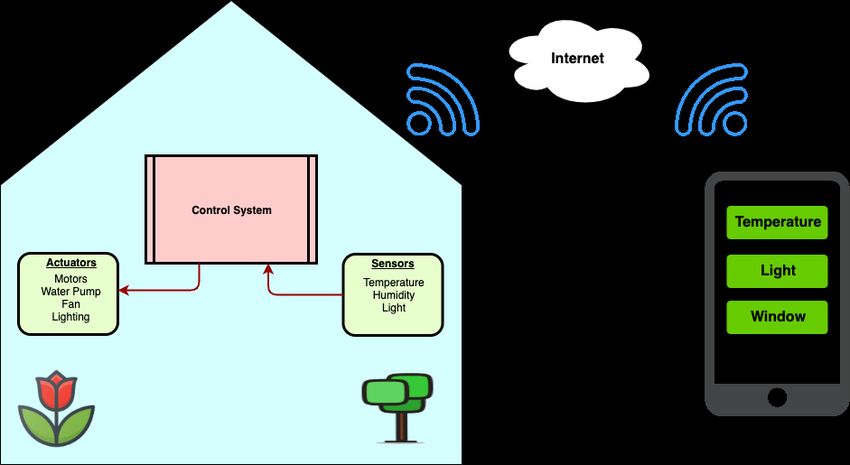
According to the architecture chapter 2.2, opportunities for architecture are many and different.
Picking the pieces out of the cake and customize an architecture aiming to fit this project are done
with aspects on a future Swedish market. To reduce dependency on internet and increases the
reliability most of the logic is put on a microcontroller. The microcontroller then communicates
with sensors and actuators via its I/O pins. Then to be able to reach the microcontroller remotely,
it is extended with a WiFi module. Web server and storage is outsourced and put into the cloud
both to avoid extra hardware and the functionality of existing web servers supplies. The server is
also working as a middle hand in between user and greenhouse. By posting a request to the web
server the user can both put instructions and retrieve data. HTTP will be used with a LAMP
stack placed in the cloud. Developing of an Android mobile application are taking place to fulfill
a full-scale system prototype.
15Figure 3.1 is an overview of the chosen system architecture and its components.
Figure 3.1: Proposed and chosen system architecture
3.1.2 Hardware
According to the related work 3.1.1 there is need for a microcontroller and WiFi module. The
chosen microcontroller is an ARM-based Atmel SAM3X8E that sits on a developer board named
Arduino Due. There are microcontroller boards that have build-in WiFi modules but the chosen
board is well known by the author’s and the limitation in time for the project made this choice to
ensure that implementation will be possible. There are few WiFi modules at the market today that
are small and provide a basic application programmer interface (API) build in to make transmission
control protocol (TCP) or user datagram protocol (UDP) connections. The WiFi module ESP8266
is successfully implemented in a similar system[26] and is therefore also selected in this prototype.
It has a small processor, low cost and a build-in API with AT commands[27] that can be used
without further configurations. Both modules also operate on the same voltage level, and the
WiFi module can be configured to act as both access point and station mode. Another feature for
further development are the deep sleep functionalities both modules includes, necessary for an end
product. More regarding the selection av hardware components can be found in the Mechatronic
Engineering parts report[5].
• Atmel SAM3X8E & Arduino Due board
The Arduino Due board consists of 54 digital I/O pins where twelve of them can be used
as PWM outputs. It also consists of twelve analog inputs with ADC built-in. It has four
dedicated ports for serial UART communication and can run with clock speed up to 84 Mhz.
The microprocessor placed at the board is a 32-bit ARM Cortex-M3 from Atmel. It has a
built-in flash of 512K bytes and a nested vector interrupt controller configurable for interrupts
on certain pins. This processor holds all the functionalities needed for the SGH.
• ESP8266
The ESP8266 is a stand-alone WiFi module from the China-based company SparkFun Elec-
tronics. It has a built-in microcontroller and a printed circuit board (PCB) WiFi antenna.
Except pins for ground and power, it has two dedicated pins for serial UART communica-
tion, two general-purpose input-output (GPIO) pins, one reset pin and one enable pin. The
ESP8266 version -01 comes with 4Mb flash memory, flashed with AT command[27] software.
The AT command version is 1.3.0.0.
• Segger j-link
For real-time hardware debugging software a Segger j-link is used, hoping to speed up the
developing process. The chosen developer board (Arduino Due) has support for connection
via a JTAG interface which is the same interface as the Segger j-link. The j-linker is also
hardware that can be borrowed from the university.
163.1.3 Software
Some parts of the software have been chosen based on the related work while other parts are
selected because of the capability of working together with the selected hardware. Parts of the
software are only used for testing and validation and speeding up the development process while
others are a part of the final prototype.
• SEGGER Embedded Studios
Segger Embedded Studios (SES) is and integrated developer environment (IDE) with the
main focus on hardware close programming. It is free of use for non-commercial, supports the
selected processor and includes necessary setup files. SES gives two language opportunities
such as C and C++ where C is chosen according to previous experience and in consolation
with the Mechatronics Engineering part. SES also works cross platforms between Windows,
Linux and OSX.
• Serial communication monitoring
While testing the ESP8266 module individually to ensure it performs as expected, a stand-
alone serial communication program where used. Both the Linux terminal program Moserial
and Arduino IDE were used to monitor serial communication.
• Android Studios
As described earlier in the report, developing a mobile application is taking place after
investigation according to 2.1 and recommendation from Willab Garden. Android Studios is
an IDE developed for developing mobile applications for the Android operating system, which
includes the feature of having an android virtual device (AVD, virtual mobile device). Java
and Kotlin are the two language opportunities, where Java is selected according to previous
experience.
• Web Server and Database
To not host own hardware and simulate the market shift towards renting resources in the
cloud[17], the webserver will be placed in Google Cloud. The chosen solution will be open
source and a commonly used solution to be able to make the project within the time limi-
tation. The system will consist of a general LAMP stack. LAMP stands for Linux, Apache,
MySql and PHP. Google Cloud also have full support and a separate service to install a
LAMP stack.
3.2 Measuring The Result
The result will be measured to confirm whether the project goals have been achieved. The three
most important factors are that the interface is pleasing to use, system reliability and system
responsiveness over a longer period. The table below describes the way the result will be measured.
• User Interface
A user interface is always self-judging in the simplicity of using it. The application will
be built around daily commonly used design and patterns that are well known for daily
smartphone users. This is to ensure a user-friendly layout and design. Since the project in
collaboration with Willab Garden aims to create a prototype as close to how a product could
look like therefore this is one of the most important measurements. A small survey will also
be done with potential users that have no experience or knowledge from the project to test
this. The survey will be setup in such way that the user shall do some predefined tasks and
execute them with no help. Then score how easy or hard it was. This measurement is done
to see if the goal of developing a mobile application prototype is fulfilled.
• System Responsiveness
This system contains both hardware that controls sensors and actuators, hardware for in-
ternet communication, web server and mobile application for the end-user. All these parts
are connected and the responsiveness will be measured in execution time, which implies the
time it takes to update the greenhouse from the webserver. of the project goals is to propose
a system architecture that can accommodate the technical and operational requirements.
This will describe how well the proposed architecture and implementation works. But also
measure how responsive the system is from a user perspective.
17• Cost
The system will be evaluated in therms of costs. Both the costs of all hardware parts that
the actual system includes, but also a monthly server-/database costs of having the system
running. A limit of 10.000 SEK is set to ensure the system is affordable to the private market.
• System Integration
The project is divided into two parts as described earlier and in the end, the two parts have
to merge and be implemented together to test the full system. All parts will be integrated
and tested inside a greenhouse provided by Willab Garden. Measurements and tests will be
done to ensure the system works as indented to satisfy the project goals. The system will also
be tested during a longer period to ensure it works properly over time. This measurement is
chosen to verify that the goal of being able to send sensor values and retrieve commands is
working as intended in the SGH.
18Chapter 4
Implementation
Implementations are divided into each module and described below. For the microprocessor, the
Atmel SAM3X/SAM3A data sheet is used as a reference manual.
4.1 Web Server
The system stores each sensor data in tables. This enables the user to show historical data views
but also to set up future automation algorithms that can be calculated in the cloud but also locally
in the embedded system, both are used in this implementation. This is to allow robustness in the
system so the system does not rely on internet connectivity to function but can close windows,
have some default watering intervals etc. Also since the embedded system is directly connected to
the internet thru a WiFi module, the ESP8266 WiFi module can be set up to be an access point
at the same time so the user could connect to the system to control it locally if needed.
Google Cloud (GC) is used as infrastructure for both storage and hosting of computational capacity
for the servers. CG is set up in such a way that it runs a Linux virtual machine that is placed at
the closest CG server from Sweden, currently Finland. The web server is configured as a LAMP
stack.
Figure 4.1: LAMP stack overview
The web server also serves the purpose of sharing information between the mobile application (the
user) and the SGH. Using a table for holding instruction values such as LED on/of enables this.
The only thing that needs to be configured on GC for Apache is to allow for outside incoming
connections over HTTP to get through the GC firewall.
4.1.1 PHP
The PHP script is created in such a way that they create URL endpoints for different functions.
It is not a full REST API used with all the HTTP methods but a simplified version. During
development, the functionalities of the script have been testes on a local setup LAMP stack. After
verifying the code works as intended it has been moved to GC.
19To enable the PHP scripts for accessing and querying the database the official MySql connec-
tion libraries (mysqli) have been used.
4.1.2 MySql
The database serves two purposes in this system which is to store historical data and status flags
of different modes and actuators. Historical data is stored from the embedded system at fixed time
intervals. Actual data that is being stored at fixed time intervals are:
• Air temperature.
• Air humidity.
• Wind speed.
Each type of data has it’s own table with a unique id and timestamp that is set by the database
when created. In this way the system can easily add more sensors and data points that are of
interest for storing.
Status flags are used slightly differently than sensor values that are accumulated in tables as
described above. The main purpose here is to have some data that describes the current state of
the greenhouse. The status flags that are stored are:
• Watering interval. The user can set how often per day the system should water.
• Watering time. Since the project assumes the user has a water supply in the greenhouse from
before with pressure a time in seconds is added for how long it should be watering.
• LED on/off. Holds the state of LED lighting.
• Roof window. Open or closes the window on a scale from 0-100%.
• Target temperature.
• Self Control and Autonomous mode. The user can set the system in self-control mode where
the user controllers all actuators manually. If switching to autonomous mode the system will
hold the target temperature and watering intervals with watering time. It can also hold a
specific moister level. The system then control’s the actuators for watering and roof windows
automatically.
When the status flags values are changed, current data points (rows in a table) values are updated.
This is to save storage space. Also after discussing what data is important to store for future
use gardener experts at Willab Garden recommended to start with the basics of temperature and
humidity since this is the two by large important values for optimal yield.
All data that is being exported (read) from the database and imported (write) is done by stored
procedures. In this way the PHP scripts can be kept at minimal and no SQL statements are
needed to be coded and sent for execution at the database. Multiple user accounts have been set
up depending on what rights are needed when modifying the database. The PHP scripts provides
a special user account with password to the database server otherwise no connection can be setup.
The storage logic is also set up in such way that the SGH can update sensor values often so the
mobile application can see real-time data. But new sensor values are only stored every 15 minutes.
204.2 Internet Connectivity
Since the WiFi module includes a flashed version of AT commands and communicates via the
UART interface, UART has to be configured on the microprocessor. UART theory is described in
section 2.6.1.
4.2.1 Internet connectivity implementation
To enable the microprocessor to handle characters sent over UART, some of its dedicated UART
pins have to be configured. This is a feature that is built in the microprocessor and can be ac-
tivated by configuring the UART registers. Since the WiFi module has a default baud rate of
115200, calculations then have to be done to set the same baud rate on the microprocessor.
According to SAM3X8E datasheet, calculations are as follows:
M CK
BaudRate =
16 ∗ CD
Figure 4.2: SAM3X8E baud rate equation
Where CD is a scaling factor and MCK is master clock speed. Both modules are also configured
to use eight-bit data packages with no parity bit. To avoid the microcontroller from polling to
check for data, it is configured to generate an interrupt for each character that arrives and stores
it in a buffer. Since the WiFi module itself has a flashed software from the factory that has AT
commands available and ready to use. This means that the WiFi module can directly be connected
to the selected and configured pins at the circuit board and be used with no more configurations.
Then by sending AT commands as a string to the WiFi module, it is forced to execute instructions.
Depending on sent AT command, the microprocessor masks out if the WiFi module is done by
searching for the ending line characters “\r\n”.
While testing the UART configurations an oscilloscope has been used to analyze voltage levels on
the TX/RX pins. Figure 4.3 shows the microprocessor sending a single character on the TX pin.
Figure 4.3: Oscilloscope UART monitoring
All the functionalities with the WiFi module and communication with the webserver was developed
in stand alone C files and header files. The purpose of this was to develop a simple API for the
other project group so they simple could make function calls from their code.
214.3 Mobile Application
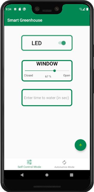
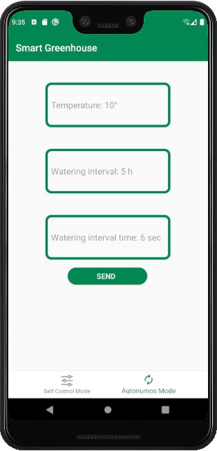
The smartphone application developed for this project is named Smart Greenhouse and developed
for smartphones using the Android operating system. It is divided into four action buttons, config-
ured with click listener for taking the user to different areas to control, monitor and overview data
of the greenhouse. The sections Live Monitoring, Control, Statistics and Web store are described
individually bellow.
Figure 4.4: Mobile application flowchart
4.3.1 Live Monitoring
In the live monitor view is where actual data from the greenhouse are displayed. It consist of
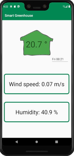
two parts, one temperature part and one dynamic scroll view part. Before displaying the con-
tent on the screen, an HTTP request is sent to the server where greenhouse data is stored.
Data is then returned in JSON array format
which in turn includes one JSON object for
each sensor. Each object consists of an id,
name and data, where the name is used by
the application to identify the type of data.
The application is going through every ob-
ject in the array and places data in a scroll
view, element after element. The scroll view
is implemented as a container of an element,
where each element is an object itself con-
taining three parts, description, data and
unit. That provides possibilities for further
development of adding new sensors for live
monitoring. A swipe to refresh function is Figure 4.5: Live monitor view
added to enables the user a swiping down
action over the screen to update the actual data. The application then sends a new HTTP request
every time a swipe action is performed and updates all objects with the newest measured data
from the database.
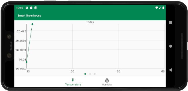
22You can also read