Characterization Of Dielectric Barrier Discharge (DBD) Produced In Air At Atmospheric Pressure And Its Application In Surface Modification Of ...
←
→
Page content transcription
If your browser does not render page correctly, please read the page content below
Journal of Technological and Space Plasmas, Vol. 1, Issue 1 (2020)

Characterization Of Dielectric Barrier Discharge (DBD) Produced In Air At
Atmospheric Pressure And Its Application In Surface Modification Of
High-Density Polyethylene (HDPE)
R. P. Guragain 1 * , H. B. Baniya 1, 2 * , S. Dhungana 1 , S. Gautam 3 , B. P. Pandey 4 , U.
M. Joshi 1 and D. P. Subedi 1
1
 Department of Physics, School of Sciences, Kathmandu University, Kavre, Nepal
2
 Department of Physics, Tri-Chandra College, Tribhuvan University, Kathmandu, Nepal
3
 Mechanical Engineering Department, University of California, Merced, 5200 N. Lake Road, Merced, CA
95343, USA
4
 Department of Chemical Science and Engineering, Kathmandu University, Kavre, Nepal

(Received: 08. May 2020, Accepted: 08. July 2020, Published online: 09. July 2020)

The low surface energy of HDPE limits its industrial uses as it is not suitable for printing and
adhesion. The main aim of this work is to improve the wetting properties of high-density
polyethylene (HDPE) using air dielectric barrier discharge (DBD) operating at the line frequency
(50 Hz). The estimation of electron temperature and electron density has been done by electrical
and optical methods. The surface roughness of the control and plasma treated polymer film is
analysed by contact angle (CA) measurement, surface energy measurement and scanning
electron microscope (SEM) analysis. The contact angle was found to be suppressed from
 0 0 0 0
93.1 ±2.0 to 64 ±1 after 10 sec of plasma treatment which implied that the surface property
had changed to a hydrophilic state caused by an increase in the surface roughness.
(DOI: 10.31281/jtsp.v1i1.11)
rayessprakash@gmail.com , hom.baniya@student.ku.edu.np

 I. Introduction physical (dry) as well as chemical (wet) methods
 have been in practice since the decade for the
High Density Poly Ethylene (HDPE) is a recyclable modification of the polymer surface. However,
thermoplastic polymer made from petroleum the chemical method is water-wasting and
product which is the most versatile plastic environment polluting. In contrast, the physical
materials around, and used in a wide variety of method has attracted much attention in recent
applications, including plastic bottles, toys, soda years [6-9].
bottles, trash cans, traffic cones bleach bottles,
cutting boards, and piping [1]. The main reason Plasma treatment is one of the versatile physical
for its wide range of applications is its superb methods for surface modification of polymers as
characteristics viz., high chemical resistance, good it does not leave any chemical residue on the
mechanical properties (high flexibility, high treated surface [10-12]. Because of the heat
tensile strength and ease of material processing), sensitivity of the polymer, non-thermal plasma
high recycling potential and low cost [2,3]. also called cold plasma is suited for its surface
However, the surface energy of HDPE is quite low modification and processing. Non-thermal
due to the absence of polar functional groups in plasma has the ability to modify the surface of
PE molecular chains [4,5], which limit their the polymer by adding specific functional groups
potential application in various fields. As a result, without altering the bulk properties of the
its surface properties such as hydrophilicity, material [13-15]. But the generation of non-
adhesivity and printability do not often meet the thermal plasma in low pressure and high
requirement for industrial applications. [5]. In frequency needs a vacuum system which
order to spread its uses in different sectors, its increases the budget of the operation and also
surface modification is necessary. Different makes it inconvenient for large scale treatment.

Vol. 1, Issue 1 - 27 © G-Labs 2020
R. P. Guragain et al. J. Technol. Space Plasmas, Vol. 1, Issue 1 (2020)

Thus, in order to minimize the operation cost and that both the contact angle and surface energy of
elaborate its uses in industrial level, the use of the material changed after being treated with the
atmospheric pressure plasma is grooming day by non-thermal plasma.
day [16-18]. In this paper, the effect of pre-
treatment of the polymer surface with non- II. Materials and Methods
thermal plasma produced at atmospheric
pressure using line frequency (50 Hz) has been Fig. 1 shows the typical experimental set up and
discussed. Non-thermal plasma generated by ac nature of the discharge used for the present
voltage source operating at the line frequency is study. The reactor system consists of a
used to modify the surface of the HDPE sample. transparent cylinder of height 10 cm, diameter 10
The surface properties of the treated materials cm and thickness 0.5 cm. An orifice is made on
were studied in terms of contact angle and the cylinder and a fibre optic cable is inserted
surface energy measurements. It was observed there and sealed.

 (1,2) Electrodes (3) Dielectric Sheet (PC) (4) Ballast Resistor (5) Shunt Resistor (6) Voltage Probe (7) Current
 Probe (8) Oscilloscope (9) Reaction Chamber (10) Vacuum Pump (11,12) Pipes (13) Pressure Gauge (14) High
 Voltage Transformer (15) Ground (16) Computer Interfacing

 Figure 1: Schematic diagram of the experimental setup and image of the discharge.

Both the electrodes used in the study are made between the electrodes was fixed at 3.5 mm. The
of brass (5.1 cm × 5.1 cm × 1.0 cm). A ac voltage applied to the reactor was measured
polycarbonate sheet of 2 mm thickness is by using a high- voltage probe (PINTEX HVP-28HF)
inserted between the two electrodes which and monitored on a digital oscilloscope (Tektronix
serves the purpose of the dielectric barrier. The TDS 2002, 60MHz). The attenuation ratio of the
reactor consists of two pipes. One of the pipes is high voltage probe is 1000:1. For displaying the
connected to a vacuum pump while the other waveform of the discharge current on the
pipe is connected to the analogue pressure oscilloscope, the reactor lower electrode was
gauge. The reactor is designed in such a way that grounded through a current measuring resistor
it can be made to operate in both the of 10 KΩ. A spectrometer of Ocean Optics (USB
atmospheric and reduced pressure (as low as 2000+) has been used for the measurement of
5300 Pa). For all DBD treatments the gap emission spectra. In this work, the operating ac

Vol. 1, Issue 1 - 28 © G-Labs 2020
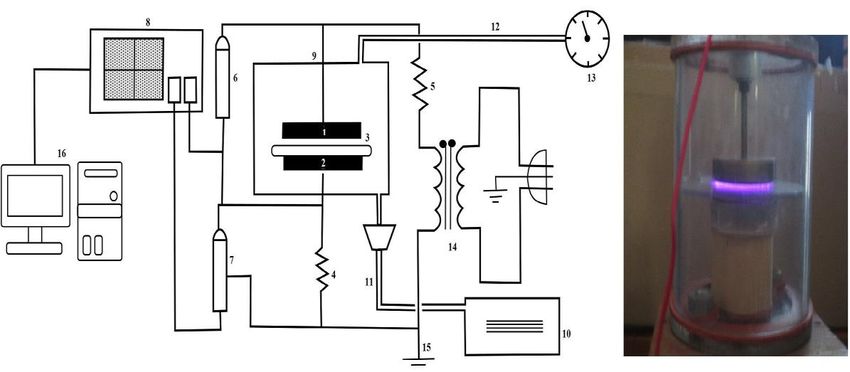
R. P. Guragain et al. J. Technol. Space Plasmas, Vol. 1, Issue 1 (2020) voltage and frequency were maintained at 11.76 and the current peaks of the falling part kV rms and 50 Hz respectively. Prior to the correspond to reverse negative polarity in which treatment, HDPE samples of dimension (50 mm × the accumulated charges are changed. The 15 mm × 0.05 mm) provided by Goodfellow, UK, current density J was obtained by dividing the were ultrasonically cleaned in distilled water for discharge current, I by the cross-sectional area of 20 minutes. To get rid of the organic plasma, A. contamination, the samples of HDPE were rinsed in methanol for 10 minutes and then dried at I room temperature in a clean environment. J (1) A The contact angle between a test liquid and the polymer surface was obtained by the sessile drop The average electron density ne can be method on a standard Rame-Hart goniometer, calculated from the following equation [19,20]. model 200 using the DROP Image software. The contact angle assessments were performed = (2) within 30 min after the treatments. All plasma treatments were administered in air at atmospheric pressure and ambient temperature. In our case, the cross sectional area of the plasma The contact angle measurement was done at four = cross sectional area of the electrodes = 20.41 different locations of the same samples and the cm², Discharge current = 22.8 mA, Applied average value of the contact angle thus obtained Voltage = 11.76 kV (rms), inter-electrode distance was used for the surface energy calculations. The (d) = 3.5 mm = 0.35 cm, electron mobility µe 552 maximum error in the contact angle assessments cm² [20, 21]. The electron mobility can be did not exceed 2%. In this work, LEO (500) /Zeiss calculated as follows: Field-emission scanning electron microscope (SEM) was used to examine surface morphology. = (3) Here, e represents the electronic charge, m represents the mass of the electron and m III. Results and Discussions represents the effective collisional frequency. III.a) Electrical Characterization The value of effective collision frequency for nitrogen is found to be [21]: 9 -1 -1 m = 4.2 x 10 s torr Substituting these values in Eq. (2), the electron mobility is estimated as 1 = 1.67 × 1015 × 3.192 ×1012 (4) → µ ≈ 552 2 / (5) Using all these values in Eq. (2), the electron 8 density was found to be in the order of 3.7 × 10 -3 cm . Figure 2: Typical current and voltage waveforms for 50 Hz DBD Fig. 2 shows the typical current and voltage waveform of DBD generated in air at atmospheric pressure condition. The current peak appears on both the rising and falling of the discharge voltage. The current peaks on the rising part correspond to positive polarity where some of the charges accumulate on the dielectric barrier Vol. 1, Issue 1 - 29 © G-Labs 2020
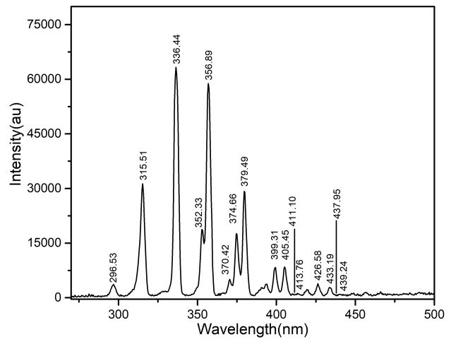
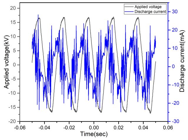
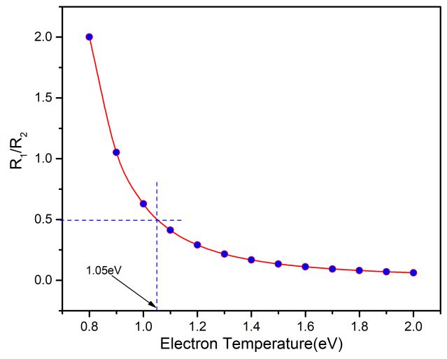
R. P. Guragain et al. J. Technol. Space Plasmas, Vol. 1, Issue 1 (2020) 1 1 2 = =( )( )( )( )( )( ) 2 3 4 − − + [− ] (6) Here, in Eq. (6), R is the ratio of the intensity of two lines, I is the intensity of the spectral line, Aij is the transition probability of the transition i j, gi is the statistical weight of the upper level, λ is the wavelength of the line radiation, Ei is the energy of the upper level, k is the Boltzmann constant and Te is the electron temperature. The values of λ and I are obtained from the Figure 3: Lissajous figure of the discharge observation, and the values of Aij, gi and Ei are at atmospheric pressure condition obtained from the National Institute of Standards and Technology (NIST) Atomic Spectra Database Fig. 3 shows the voltage-versus-charge plot or the [24]. so-called Lissajous figure of the discharge operating using line frequency at atmospheric Tab. 1 shows the corresponding values of the condition. The energy dissipated per cycle is ratio of the intensity of the spectral lines with the found to be 0.4184 mJ per cycle. change in electron temperature. III.b) Optical Characterization of the Table 1: Electron temperature and its discharge corresponding intensity ratio Fig. 4 shows the spectra of the discharge and Electron Ratio of intensity of their corresponding intensities at atmospheric Temperature (Te) Spectral Lines (R2/R1) pressure condition. 0.8 2.00173 0.9 1.05178 1.0 0.62855 1.1 0.41248 1.2 0.29038 1.3 0.21576 1.4 0.16727 1.5 0.13415 1.6 0.1106 1.7 0.09327 Figure 4: Spectra of the discharge at a 1.8 0.08017 frequency of 50 Hz in an atmospheric condition. 1.9 0.07001 The line intensity ratio method was employed for 2.0 0.06197 the estimation of electron temperature [22,23]. In this method four suitable lines; two for N I (413.7640 nm, 439.241 nm) and two for N II (411.1039 nm, 437.9585 nm) were chosen from spectral lines of Nitrogen obtained from the discharge. Vol. 1, Issue 1 - 30 © G-Labs 2020
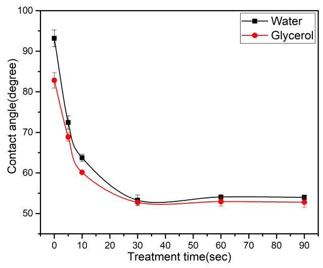
R. P. Guragain et al. J. Technol. Space Plasmas, Vol. 1, Issue 1 (2020)

 Eqs. (8) and (9). The sum of these two quantities
 eventually gives the total surface energy of the
 solid.

 The influence of treatment time on the wettability
 was investigated, using a Rame Hart contact
 angle goniometer (model 200) using two test
 liquids (water and glycerol) on the surface of the
 HDPE.

 Figure 5: Plot of R1/R2 as a function of T.

From Fig. 5, the electron temperature is found to Figure 6: Water contact angle of control (a)
be about 1.05 eV. This temperature is favourable and plasma treated(b) HDPE thin films for
for the surface modification of the polymeric 10 sec.
 Fig. 6 shows the images of the untreated and
films as the discharge used for material
 9 12 plasma treated high density polyethylene films
processing typically have densities of 10 -10 .
 3 for 60 seconds. When polymers are exposed to
/cm and electron temperature in the range 1-10
 plasma, basically two phenomena occur
eV [25,26].
 simultaneously. First is etching of the polymer
 surface through the reaction of atomic oxygen
 III.c) Polymer wettability
 with the surface carbon atoms, giving volatile
 reaction products. Second is the formation of
The wettability of polymer indirectly indicates its
 oxygen functional groups at the polymer surface
susceptibility to molecular interaction with the
 through the interaction between the active
liquid phase and the presence of polar groups on
 species in plasma and the surface atoms [30].
the surface. WCA measurements can provide
some qualitative information about the polymer
surface modification [27].

For an ideal, smooth and homogeneous surface,
the water contact angle and surface free energy
are measured at the equilibrium according to the
Young's equation and Owens Wendt Kaeble
methods respectively [28,29].

 −
 = (7)

Where, γsv is the surface free energy of the solid
substrate, γsl is the interfacial tension (interfacial
free energy) between the solid and the liquid and
γlv is the surface tension of the liquid.
 Figure 7: Variation of the contact angle as a
For two liquids j and k, function of treatment time.

 Fig. 7 shows the water contact angle (WCA) of
 (1 + ) = 2( )1/2 + 2( )1/2 (8)
 DBD-treated HDPE films as a function of
 treatment time. Here, the water contact angle of

 1/2
 (1 + ) = 2( ) + 2( )1/2 (9) the untreated sample of HDPE was found to be
 0 0
 93 ±2 . After 10 sec of plasma treatment, the
Using the values of the surface tension, polar and water contact angle was significantly decreased
dispersion components of the test liquids, 0 0
 to 64 ±1 as depicted in Fig. 7 exhibiting that DBD
components of surface free energy of the solid, treatment can be used for improving the surface
 p d
i.e. γ s and γ s can be determined by solving the wettability. This might be due to the

Vol. 1, Issue 1 - 31 © G-Labs 2020
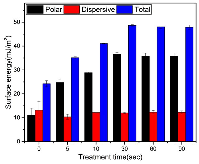
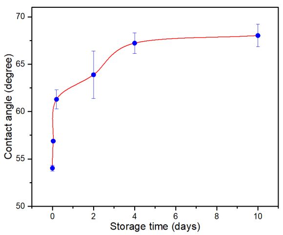
R. P. Guragain et al. J. Technol. Space Plasmas, Vol. 1, Issue 1 (2020)

incorporation of new oxygen related functional III.d) Ageing effect:
groups on the surface. However, the extension of
the treatment time did not result in further One of the most important challenges in plasma
improvement of polymer hydrophilicity and the processing is to achieve a long-lasting treatment
WCA of plasma modified HDPE attained effect. The change in the contact angle of the 60
 0 0
saturation value of around 54.1 ±0.3 . This might seconds plasma treated HDPE films was
suggest that the etching and the oxidation come monitored for 10 days. Distilled water was only
to a saturation when the surface of samples are used for the measurement of contact angle.
exposed to the air-DBD [30,31].

 Figure 9: Variation of contact angle with
 Figure 8: Variation of the surface free
 storage time
 energy as a function of treatment time.

 It is seen that the water contact is found to be
Fig. 8 shows the variation of surface energy as a changed more rapidly for the first few hours and
function of treatment time. The surface energy of then changes very slowly to reach a stable value
 2
the untreated HDPE film was 24±1 mJ/m . Plasma 0
 of about 68 which is still smaller than the
treatment appears to increase the surface energy untreated HDPE films. The change in the contact
up to 30 seconds exposure time; and thereafter angle might be due the change in the polymer
tending to saturate. This may be due to the lack chain motion, reorientation of the polar group
of any change in the oxygen content incorporated into the polymer bulk or only within the modified
into the surface, as the exposure time increased. surface. The decay in wettability might be due to
Finally, the surface energy saturates at 48±1 the reduction of the hydrophilic functional groups
 2
mJ/m . Similar trend is observed for the polar and partially due to hydrocarbon re-adsorption.
component. It might be due to the incorporation
of polar groups such as C=O, -OH, -COO etc. III.e) Surface morphology:
[31,32]. The dispersive component almost
remains constant. This component does not have During plasma treatment, energetic plasma
any contribution to increase the wettability of species bombard and cause etching of HDPE
HDPE films. Hence the increase in surface energy films surface, leading to an increase in the
is mainly due to the incorporation of polar groups surface roughness [32,33].
onto the HDPE surface. The details of this
oxidation, leading to the enhanced hydrophilicity Fig. 10 shows the SEM morphology of untreated
observed has been assessed by ATR-FTIR, XPS and plasma treated HDPE films at 60 seconds.
analyses by various researchers [30-32]. The morphology of the control sample is
 smoother than that of the plasma-treated one.
 The gradual increment in the particle grain size
 with the image scan area can be realized. The
 increase in the surface roughness of the HDPE
 film could have been caused by the excited
 reactive species from the discharge plasma in the
 ambient air. These highly reactive species could
 have etched and roughened the film surface. This

Vol. 1, Issue 1 - 32 © G-Labs 2020
R. P. Guragain et al. J. Technol. Space Plasmas, Vol. 1, Issue 1 (2020)

increase in the surface roughness might be in contact with the air is activated, ionized and
responsible for the decrease in the contact angle. dissociated in the discharge to give extremely
 reactive oxygen species which can readily react
 with the HDPE films. Ageing effect showed that
 the so-called hydrophobic recovery of the HDPE
 films occurred as the storage time increased. The
 results from the SEM measurement showed a
 gradual increase in the surface roughness of the
 plasma treated surface with treatment time. The
 morphological changes made on the surface of
 HDPE films lead to increase in hydrophilic
 properties. It is further seen that there is a direct
 relationship between the roughness of the
 surface and the wettability. The results from
 sessile drop examination confirmed that contact
 angle of HDPE decreases as surface roughness
 increases. The effect will find attraction on
 industrial applications. In the present study, it is
 evident that more than 40% decrease in the value
 of water contact angle is achieved in just 30
 second of exposure to plasma. Therefore, quick
 hydrophilization of HDPE using cost-effective
 plasmas devices could be the novelty of the
 present work. Thus, the results from our
 experiment showed that the atmospheric
 pressure plasma treatment operating at 50 Hz
 could be a cost-effective technology to improve
 the wettability of HDPE films as compared to rf-
 sources operating at high frequencies.

 Figure 10: SEM images of the V. Acknowledgments
 control(untreated) and Plasma treated HDPE
 films The authors would like to thank Prof. Andrzej
 Huczko and his team of University of Warsaw,
Several other authors have also reported a Poland for their valuable help and support for the
similar roughness trend for the plasma-treated SEM analysis of the polymer samples. The
polymers [31-35]. corresponding author was supported by the
 Nepal Academy of Science and Technology
 (NAST), Nepal, through Grant No. (2076/077). The
 IV. Conclusions
 authors would also like to acknowledge Prof.
 Johannes Gruenwald, Prof. Duc Ba Nguyen and all
In this work, an atmospheric pressure plasma has
 the researchers of Kathmandu University Plasma
been used to modify HDPE film surfaces using
 Physics Laboratory who provided valuable
line frequency (50 Hz). Electron density and
 suggestions and help for the completion of the
temperature of the discharge were found to be
 8 3 work.
3.7×10 /cm and 1.05 eV respectively. The plasma
treatment can greatly change the surface
chemistry as well as morphology of HDPE films. VI. References
The polar functional groups generated due to
plasma treatment on the surface of HDPE films [1] G. Wypych, “HDPE high density polyethylene,
cause decrease in contact angle and rise in Handbook of Polymers”, Elsevier., p.150-156,
surface energy. The reduction of the water 2012.
contact angles on treated HDPE films as [2] H. Ulrich, “Introduction to Industrial
compared to the untreated (control) one shows Polymers”,2
 nd
 edition, Hanser Publishers.,
the strong increased wettability induced by the New York, 1993.
air-DBD even after such short treatment time.
This behaviour can be attributed to strong [3] S. Bhowmik, P. K. Ghosh, and S. Ray,
surface oxidation. The molecular oxygen which is “Surface modification of HDPE and PP by

Vol. 1, Issue 1 - 33 © G-Labs 2020
R. P. Guragain et al. J. Technol. Space Plasmas, Vol. 1, Issue 1 (2020)

 mechanical polishing and DC glow discharge [13] M. Nitschke, “Plasma Modification of
 and their adhesive joining to steel”, Journal Polymer Surfaces and Plasma
 of Applied Polymer Science., 80(8),1140– Polymerization”. In: Stamm M. (eds) Polymer
 1149, 2001. Surfaces and Interfaces. Springer, Berlin,
 Heidelberg, 2008.
[4] J.-S. Lim, M.-S. Kook, S. Jung, H.-J. Park, S.-H.
 Ohk and H.-K. Oh, “Plasma Treated High- [14] A.P. Napartovich, “Overview of Atmospheric
 Density Polyethylene (HDPE) Medpor Pressure Discharges Producing Nonthermal
 Implant Immobilized with rhBMP-2 for Plasma”, Plasmas and Polymers., 6, 1–14,
 Improving the Bone Regeneration”, Journal 2001.
 of Nanomaterials., 1–7, 2014.
 [15] R. P. Guragain, S. Gautam, D. P. Subedi and
[5] H. Drnovská, L. Lapčík, V. Buršíková, J. R. Shrestha, “Effect of Plasma Treatment on
 Zemek and A. M. Barros-Timmons, “Surface the Surface of Polyethylene Terephthalate
 properties of polyethylene after low- with 50Hz Dielectric Barrier Discharge at
 temperature plasma treatment”, Colloid and Near Atmospheric Pressure”, International
 Polymer Science., 281(11): 1025–1033, 2003. Journal of Recent Research and Review.,
 9(4),34-37, 2016.
[6] U. M. Joshi and D. P. Subedi, “Surface
 treatment of high-density polyethylene [16] S. K. Nemani, R. K. Annavarapu, B.
 (HDPE) film by 50 Hz dielectric barrier Mohammadian, A. Raiyan, J. Heil, M. A.
 discharge produced in air and argon/air Haque, H. Sojoudi, “Surface Modification of
 mixture at atmospheric pressure”, Int. Polymers: Methods and Applications”.
 Journal of Engineering Research and Advanced Materials Interfaces., 1801247: 1-
 Applications., 5(3): 1-9, 2015. 26, 2018.

[7] W. Kun, L. Jian, R. Chunsheng, W. Dezhen [17] H. M. S. Iqbal, S. Bhowmik, and R.
 and W. Younian, “Surface Modification of Benedictus, “Surface modification of high-
 Polyethylene (PE) Films Using Dielectric performance polymers by atmospheric
 Barrier Discharge Plasma at Atmospheric pressure plasma and failure mechanism of
 Pressure”, Plasma Science and Technology., adhesive bonded joints”. International
 10(4): 433–437, 2008. Journal of Adhesion and Adhesives., 30(6),
 418–424, 2010.
[8] J. Gruenwald, K. Fricke, M. Fröhlich, J. F. Kolb
 and M. Polak, “Deposition of Copper Oxide [18] H. Dvořáková, J. Čech, M. Stupavská, L.
 Coatings with an Atmospheric Pressure Prokeš, J. Jurmanová, V. Buršíková, J. Ráhel
 Plasma Source: II -Characterization of the and P. St’ahel, “Fast Surface Hydrophilization
 Films”, Plasma Processes and Polymers, via Atmospheric Pressure Plasma
 13(8), 766–774, 2016. Polymerization for Biological and Technical
 Applications”. Polymers (Basel)., 11(10):
[9] R. P. Guragain, S. Gautam, R. Shrestha, and
 1613, 2019.
 D. P. Subedi, “Surface modification of
 polycarbonate by treatment with 50Hz [19] F. Martinek, “Thermodynamic and electrical
 dielectric barrier discharge at near properties of nitrogen at high
 atmospheric pressure”, International Journal temperatures”. in Proc. Int. Symp. Thermal
 of Science and Research., 5(2), 1468–1470, Properties, IN, US, p. 130, 1959.
 2016.
 [20] A. El-Zein, M. Talaat, G. El-Aragi, and A. El-
[10] M. J. Shenton and G. C. Stevens, “Surface Amawy,“Electrical Characteristics of
 modification of polymer surfaces: Nonthermal Gliding Arc Discharge Reactor in
 atmospheric plasma versus vacuum plasma Argon and Nitrogen Gases”. IEEE
 treatments”, Journal of Physics D: Applied Transactions on Plasma Science.,
 Physics., 34(18), 2761–2768, 2001. 44(7),1155–1159, 2016.

[11] Rory A. Wolf, “Atmospheric Pressure Plasma [21] J. P. Rajzer. “Gas discharge physics”. Berlin:
 for Surface Modification”, John Wiley and Springer, 1997.
 Scrivener Publishing, 2012.
 [22] C. S. Wong, & R. Mongkolnavin. “Elements of
[12] M. Strobel, C.S. Lyons and K.L. Mittal, Plasma Technology”, Springer Briefs in
 “Plasma Surface Modification of Polymers: Applied Sciences and Technology., 2016.
 Relevance to Adhesion”. CRC Press, 1994.
 [23] H. B. Baniya, R. Shrestha, R. P. Guragain, M.
 B. Kshetri, B. P. Pandey and D.P. Subedi,

Vol. 1, Issue 1 - 34 © G-Labs 2020
R. P. Guragain et al. J. Technol. Space Plasmas, Vol. 1, Issue 1 (2020)

 “Generation and Characterization of an surface modifications and the relevance for
 Atmospheric-Pressure Plasma Jet (APPJ) and adhesion”, International Journal of Adhesion
 Its Application in the Surface Modification of and Adhesives., 24(2): 171–177, 2004.
 Polyethylene Terephthalate”, International
 [32] A. P. Kharitonov, G. V. Simbirtseva, A.
 Journal of Polymer Science, 1687-9422, 2020.
 Tressaud, E. Durand, C. Labrugère, and M.
[24] A. Kramida, Y. Ralchenko, J. Reader, and NIST Dubois, “Comparison of the surface
 ASD Team. NIST Atomic Spectra Database, modifications of polymers induced by direct
 2019. https://physics.nist.gov/asd fluorination and rf-plasma using fluorinated
 gases”, Journal of Fluorine Chemistry., 165:
[25] E. H. Lock, R. F. Fernsler and S. G. Walton.
 49–60, 2014.
 “Experimental and theoretical evaluations of
 electron temperature in continuous electron [33] G. Borcia, C. A. Anderson, and N. M. D.
 beam generated plasmas”, Plasma Sources Brown, “Dielectric barrier discharge for
 Science and Technology., 17(2), 025009, surface treatment: application to selected
 2008. polymers in film and fibre form”, Plasma
 Sources Science and Technology., 12(3),
[26] H. B. Baniya, R. P. Guragain, B. Baniya and D.
 335–344, 2003.
 P. Subedi, “Experimental Study of Cold
 Atmospheric Pressure Plasma Jet and Its [34] C.-S. Ren, K. Wang, Q.-Y. Nie, D.-Z. Wang, and
 Application in the Surface Modification of S.-H. Guo, “Surface modification of PE film by
 Polypropylene”, Reviews of Adhesion and DBD plasma in air”, Applied Surface Science.,
 Adhesives, Scrivener Publishing, 1-14, 2020. 255(5): 3421–3425, 2008.

[27] K. G. Kostov, T. M. C. Nishime, L. R. O. Hein, [35] V. Švorčík, K. Kolářová, P. Slepička, A.
 and A. Toth, “Study of polypropylene surface Macková, M. Novotná, and V. Hnatowicz,
 modification by air dielectric barrier “Modification of surface properties of high
 discharge operated at two different and low-density polyethylene by Ar plasma
 frequencies”, Surface and Coatings discharge”, Polymer Degradation and
 Technology., 234: 60–66, 2013. Stability.,91(6),1219–1225, 2006.
[28] Y. Yuan and T. R. Lee, “Contact angle and
 wetting properties,” in Surface Science
 Techniques, G. Bracco and B. Holst, Eds.,vol.
 Open Access. This article is licensed under a Creative
 51 of Springer Series in Surface Sciences,
 Commons Attribution 4.0 International License, which
 Springer, Berlin, Heidelberg, 2013. permits use, sharing, adaptation, distribution and
[29] D. K. Owens, and R. C. Wendt, “Estimation of reproduction in any medium or format, as long as you
 give appropriate credit to the original author(s) and the
 the surface free energy of polymers”, Journal
 source, provide a link to the Creative Commons license,
 of Applied Polymer Science., 13(8), 1741–
 and indicate if changes were made. The images or other
 1747, 1969. third party material in this article are included in the
[30] M. Morra, E. Occhiello, and F. Garbassi, article s Creative Commons license, unless indicated
 otherwise in a credit line to the material. If material is
 “Surface characterization of plasma-treated
 not included in the article’s Creative Commons license
 PTFE”, Surface and Interface Analysis., 16(1- and your intended use is not permitted by statutory
 12): 412–417, 1990. regulation or exceeds the permitted use, you will need
 to obtain permission directly from the copyright holder.
[31] M. Noeske, J. Degenhardt, S. Strudthoff and
 To view a copy of this license, visit:
 U. Lommatzsch, “Plasma jet treatment of
 http://creativecommons.org/licenses/by/4.0/.
 five polymers at atmospheric pressure:

Vol. 1, Issue 1 - 35 © G-Labs 2020
You can also read