Method to determine the local load cycles of a blade bearing using flexible multi-body simulation
←
→
Page content transcription
If your browser does not render page correctly, please read the page content below
Forsch Ingenieurwes
https://doi.org/10.1007/s10010-021-00457-y

 ORIGINALARBEITEN/ORIGINALS

Method to determine the local load cycles of a blade bearing using
flexible multi-body simulation
S. Leupold1      · R. Schelenz1 · G Jacobs1

Received: 22 December 2020 / Accepted: 4 March 2021
© The Author(s) 2021

Abstract
Conventional methods for designing rolling bearings against fatigue assume that a bearing ring is fully rotating and that the
load is ideally distributed over the rolling elements. Blade bearings in wind turbines, are operated under oscillating motions
and dynamic loads. The load distribution is strongly dependent on the stiffness of the bearing rings and the surrounding
structural components. This has been shown in numerous studies using FEM simulations for static load cases. In this
paper a method is presented that reduces the calculation effort of the deformation of the bearing rings, so that a flexible
integration into an aeroelastic mbs model of a wind turbine is possible. Thereby an average accuracy of 6.5% between
FEM and mbs could be achieved. The model allows the determination of time series of the global load distribution of each
raceway. By data processing of the simulation results, the number of load cycles and the maximum contact pressure for
individual segments of the raceways could be determined and their fatigue probability could be estimated using the linear
damage hypothesis according to Palmgren-Miner.

Methode zur Bestimmung der lokalen Lastwechsel von Rotorblattlagern mithilfe der flexiblen
Mehrkörpersimulation

Zusammenfassung
Konventionelle Methoden zur Auslegung von Wälzlagern gegen Ermüdung gehen davon aus, dass ein Lagerring voll um-
läuft und die Last ideal auf die einzelnen Wälzkörper verteilt wird. Blattlager in Windkraftanlagen, werden hingegen unter
oszillierenden Bewegungen und dynamischen Belastungen betrieben. Die Lastverteilung ist stark von der Steifigkeit der La-
gerringe und der umgebenden Strukturbauteile abhängig. Dies wurde in zahlreichen Studien anhand von FEM-Simulationen
für statische Lastfälle gezeigt. In dieser Arbeit wird eine Methode vorgestellt, die den Berechnungsaufwand für die Verfor-
mung der Lagerringe reduziert, so dass eine flexible Integration in ein aeroelastisches MKS-Modell einer Windkraftanlage
möglich ist. Dabei konnte eine durchschnittliche Genauigkeit von 6,5% zwischen FEM und MKS erreicht werden. Das
Modell erlaubt die Simulation von Zeitreihen der globalen Lastverteilung jeder Laufbahn. Durch Datenverarbeitung der
Simulationsergebnisse werden die Anzahl der Lastzyklen und die maximale Kontaktpressung für einzelne Segmente der
Laufbahnen bestimmt und deren Ermüdungswahrscheinlichkeit unter Verwendung der linearen Schädigungshypothese nach
Palmgren-Miner abgeschätzt.

                                                                 1 Introduction

                                                                 Blade bearings in wind turbines connect the hub and the ro-
                                                                 tor blade, so that a rotation of the blade is possible and thus
                                                                 the power input and occurring wind loads can be controlled.
 S. Leupold
    samuel.leupold@cwd.rwth-aachen.de
                                                                 Since the blade bearing is also part of the supporting struc-
                                                                 ture, a failure of the blade bearing can lead in the worst
1
    Center for Wind Power Drives, RWTH Aachen,                   case to a loss of the rotor blade.
    Campus-Boulevard 61, 52074 Aachen, Germany                      In the majority of wind turbines of the 3 MW classes,
                                                                 double-row four-point contact bearings are used as blade

                                                                                                                     K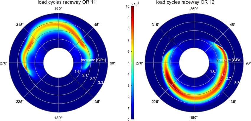
Forsch Ingenieurwes

                                                                           Due to the unusual movement pattern and the resulting poor
                                                                           lubrication of the rolling contact, most common damages
                                                                           of the rotor blade bearings are related to wear, e.g. false
                                                                           brinelling [2]. However, control strategies such as individ-
                                                                           ual pitch control (IPC), which increase the movement ac-
                                                                           tivity of the bearing, can also bring fatigue damages of the
                                                                           raceway to the fore [3].
                                                                               In conventional approaches for blade bearing design, the
                                                                           cross-section loads and pitch movements are determined by
                                                                           a aeroelastic multi-body simulation (mbs) model of the tur-
                                   Fig. 1 Cross section of a two           bine. Then the occurring oscilltions movements are counted
                                   row four point bearing. The             and classified by the oscillation angle [4, 5]. The load is av-
                                   load is transferred in the marked       eraged during the oscillation movement. The load direction
                                   diagonals for axial force and           and load cycles due to dynamic loads while the bearing is
                                   bending moments
                                                                           standing still are usually neglected. The influence of the
                                                                           stiffness of the surrounding structural components such as
                                                                           hub and rotor blade on the global load distribution on the
bearings. As shown in Fig. 1, the bearing consists of two                  individual rolling elements is well investigated for static
rows of rolling elements and eight raceways. Depending                     load cases but usually only simplified considered during
on its direction the load is transmitted between the inner                 the design of the bearing against fatigue [5–9].
and outer ring via four possible load diagonals. The angle                     In this paper, a method of determining the global load
at which the loads are transmitted changes with increasing                 distribution through flexible mbs and local load counting to
load. Under normal conditions only one diagonal of each                    determine the load cycles of each raceway segment is pre-
rolling elements is loaded.                                                sented. Thereby, the change of the global load distribution
   In comparison to conventional bearings, blade bearings                  due to the deformation of the bearing rings, the distribution
are not operated in full rotation, but stand still for a large             of the load on different raceways, the dynamic load and
part of the operating time or oscillating with small angles in             load direction are taken into account.
the range of approx. 0.2–10°. Additionally, high dynamic
bending moments occur due to wind and weight forces [1].

Fig. 2 Overview of the used tool chain to simulate the local load cycles

K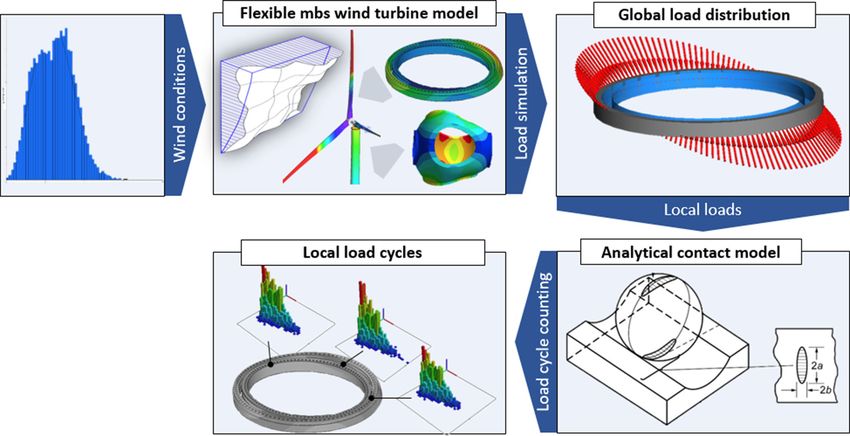
Forsch Ingenieurwes

2 Methods                                                         Table 1 Design Parameter of the turbine and pitch bearing
                                                                  Parameter                             Value                 Unit
An overview of the presented method for determining the           Rated Power                           3.0                   MW
local load cycles on individual sections of the bearing race-     Rotor diameter                        100                   m
ways over the entire service life of the wind turbine is          Hub height                            85                    m
shown in Fig. 2. In a first step, an aero elastic mbs wind        Wind class (IEC 61400)                IA                    –
turbine model [10] is extended by a flexible hub and bearing      Controller                            CPC, variable speed   –
rings. Using force elements [11], time series of the global       Wind speed (cut in/rated/cut out)     3/12/25               m/s
load distribution on each rolling element can be calculated,      Pitch bearing diameter                2.3                   m
under consideration of the deformation of the surround-           Ball number                           139                   –
ing structural components. All relevant design load cases         Ball diameter                         45                    mm
according to IEC 61400 [12] can be simulated. The time
series of the global load distribution are converted to a local
contact pressure distribution using Hertzian contact theory.         In the mbs environment Simpack the individual rolling
Finally, the pressure cycles occurring on each single seg-        element loads are calculated using the force element 88:
ment over time are counted using a load counting algorithm        “Rolling Bearing”. The stiffness of the rolling contact is
and extrapolated to the total service life of a turbine.          calculated using the Hertzian contact theory and modelled
                                                                  with non-linear springs. As shown in Fig. 3, for every time
2.1 Flexible mbs wind turbine model                               step the displacement of each spring is determined by the
                                                                  two closet flexible nodes of outer and ring. The calculated
The starting point of the calculation of the global load dis-     normal force is applied locally on these flexible nodes. The
tribution is a conventional aeroelastic model of a turbine,       load is distributed to both nodes on the inner and outer
modelled in Simpack. The general design parameters of the         ring using a spline interpolation. This allows larger relative
wind turbine and the blade bearing are given in Table 1. To       rotation between both bearing rings and thus a realistic rep-
determine an accurate global load distribution in the bear-       resentation of the pitch movement without load jumps on
ing, the flexibility of the bearing rings and the surrounding     the flexible bearing rings.
structural components must be taken into account. For this           With the described mbs model, time series of the bearing
purpose, two separate parts are modelled in FEM, the hub          load distribution and the position of the rolling elements are
connected the outer ring and the inner ring connected rotor       calculated for the most fatigue relevant design load case
blade. Additional 27 retained nodes with three translatory        DLC 1.1, according IEC 61400. [5]. For each average wind
degrees of freedom are defined on each bearing row and            speed in the range of 3–25 m/s six different wind filed with
connected to a local area of the raceway. To be able to use       a length of 800 s are simulated.
the bodies in the mbs environment, both are modally re-
duced using the Craig-Bampton method [13]. In contrast to         2.2 Analytical contact model
FEM, the deformation of the bodies in mbs is calculated
using constraint modes and constrained normal modes. The          Based on the Hertzian contact theory [14] the width (w)
constraint modes represent the static deformation of the re-      and the contact pressure distribution p(x) of the contact
tained nodes under load. They are calculated by fixing all        ellipse can be calculated for the simulated normal forces of
but one degree of freedom of the retained nodes and de-           each rolling contact. An increase of the maximum contact
termining the static shape of the deformation. Thus, the          pressure due to a truncation of the contact ellipse at high
number of constraint modes corresponds to the number of           loads is neglected. The geometry parameters of the bearing
degrees of freedom of the retained nodes. The constrained         are given in Table 1. As shown in Fig. 4, each raceway
normal modes represent the natural vibration of the body.         is divided into 12,371 individual segments leading to an
They are calculated by fixing all degrees of freedom of the       element width of 0.58 mm. Depending on the position of
retained nodes and calculating the eigenmodes of the body.        the rolling element, the local pressure is applied on specific
In Simpack deformation caused by external forces and con-         areas of the raceway. Both the motion of the inner ring
straints are evaluated only for the defined retained nodes.       and the rolling elements are taken into account. It can be
Thereby, the degrees of freedom are reduced enormously            assumed that the rolling elements migrates over time. This
and thus the computation time. The number of retained             means that at a certain pitch angle, not always the same
nodes of the reduced model was selected in such a way             raceway segments are loaded. In order to take this into
that a good agreement with simulation results of static load      account, the pressure distribution calculation is carried out
cases in the FE model is guaranteed.                              for different starting positions of the rolling elements in

                                                                                                                          K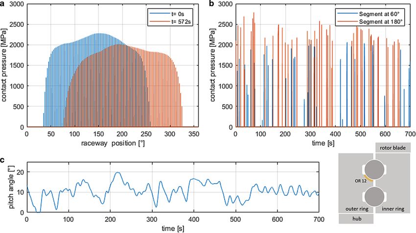
Forsch Ingenieurwes
Fig. 3 Scheme for calculating
the local rolling element load Fig. 4 Calculation of the local pressure according to the Hertzian con-
tact theory
the range between 0–2.56° which corresponds to the ball havior varies a lot within a bearing type, a large number of
distance. tests are necessary for reliable results. Currently, not enough
tests have been carried out to determine a reliable service
2.3 Local load counting life. The damage factors presented in this paper are only
given to clarify the method.
Based on the time series of the local contact pressure, the
number of overrollings is counted for each segment. By
means of a bin counting, the number of load cycles are de- 3 Results
termined and classified according to the maximum contact
pressure. The interval width of the bin counting is 25 MPa. 3.1 Flexible mbs wind tubrine model
Thus, the absolute frequency for different maximum con-
tact pressures can be determined for each segment. Load Comparison of static load cases In a first step simulation
cycles due to dynamic loads when the bearing is not mov- results of the global load distribution with the conventional
ing are neglected in this this work, but can be taken into modelling approach in FEM and the simplified modelling
account with the presented method without much additional in mbs for static load cases are compared. Therefor a model
effort. The amount of load cycles determined for the differ- consists of a rotor blade, stiffening ring, blade bearing and
ent wind speeds are extrapolated for a wind turbine lifetime hub is built up. The hub is fixed at the flange to the main
of 20 years based on the probability of occurrence for an shaft in all degrees of freedom. At the rotor blade in 20 m
IA wind location. The probability of occurrence of the indi- distance to the blade bearing forces in flap- and edgewise
vidual wind speeds is determined by means of the Rayleigh direction are applied, so that for each load case a resulting
function Pr given in DIN 61400. bending moment of 8 MNm is applied to blade bearing.
2 These loads correspond to the maximum load during power
V0
Pr .V0 / = 1 − e
− 20m=s
(1) production determined in the aeroelastic mbs model. The
load direction is varied between –45°, 0° and 45° and the
To estimate the fatigue behaviour, the damage equivalent pitch angle between 0 and 35°.
load (DEL) is determined for each segment. The different Fig. 5 shows, the global load distribution of the FEM
load collectives are summarized using the Palmgren-Miner and MBS model for six different load cases. Additionally,
linear damage hypothesis [15]. the theoretical load distribution for rigid bearing rings is
shown. The colors represent the four possible load diago-
j
X ni nals, which are shown in Fig. 1. The influence of flexible
D= (2)
Ni bearing rings depends on the load direction and pitch an-
i
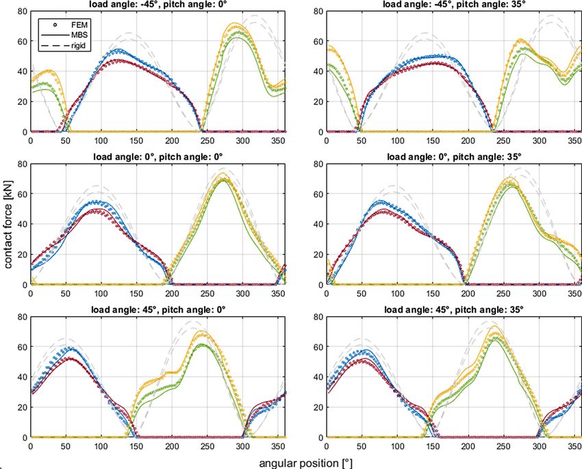
gle. The influence is very high for a load angle of –45° with
Where i is load case number, j the total number of loads, a maximum difference of 100% between the FEM model
ni the number of load cycles and Ni number of load cycles and rigid system. The reason therefor is a comparatively
to failure. low stiffness in the area around of 320°. This results in
The number of load cycles to failure Ni, is determined a high reduction of the load distribution in this area. For
based on a fatigue test carried out on a full-size blade bear- a load angle of 0°, the influence is with a difference of 25%
ing and a slope of a single logarithmic S-N curve of –0.33, much lower, due to a comparatively homogeneous stiffness
which is usual for ball bearings [16]. Since the fatigue be- in the highest loaded area.
K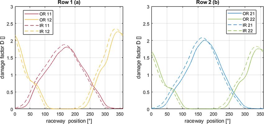
Forsch Ingenieurwes

Fig. 5 Comparison of the global load distribution of the FEM- and MBs model for different load directions and pitch angles. The different colors
represented the four possible load diagonals of the bearing. The grey lined represent the load distribution for ideal stiff bearing rings

   The load distributions simulated with the reduced mbs                  In only one of the three rotor blades the blade bearing is
model show a very good agreement with the results of the                  implemented. The simulation time increases by a factor of
FEM model for all load cases. The average error is 6.5%                   4 compared to an aeroelastic mbs model with flexible ro-
considering all rolling elements above a load of 10 kN. The               tor blades and tower considering natural frequencies up to
maximum positive deviation is 5.6 kN, the maximum neg-                    20 Hz.
ative is –3.8 kN. The difference of the service life time                    Fig. 6 shows an example of the load distribution of the
according to ISO TS 16281 [17] is about 1.5% between the                  load diagonal 12, according to Fig. 1, for six different time
FEM and mbs model and about 56% between the FEM and                       steps, of a simulation of a wind field with an average wind
the rigid model.                                                          speed of 14 m/s. Visible is the angular shift of the load max-
   The simulation time is reduced from about 1.2 h to about               imum due to a changing load direction and the increase of
2 sec. Thus a sufficient model reduction could be achieved                the maximum normal forces due to an increased amplitude
to integrate the blade bearing into the aeroelastic wind tur-             of the applied bending moment. In addition, the influence of
bine model.                                                               the stiffness of the structural components on the load distri-
                                                                          bution is shown by their deviation from an ideal sinusoidal
Load series for the turbine model The mbs wind turbine                    shape.
model is able to simulate time series for the global load
distribution for the four load diagonals and the pitch angle.

                                                                                                                                    K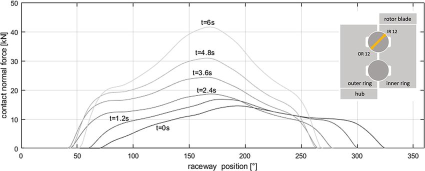
Forsch Ingenieurwes

Fig. 6 Global load distribution of load diagonal 12 for different time steps

Fig. 7 a Contact pressure distribution off all segments for two different time steps. b Time series of the occuring lod cycles for two different
raceway segments. c Time series of the simulates pitch angle

3.2 Local pressure distribution                                                   Fig. 7a shows the contact pressure for all segments of
                                                                               raceway OR 12 according to Fig. 1, for two different time
Using Hertzian contact theory, the simulated normal forces                     steps. Due to the dynamic load and direction, the shape of
are converted into local pressures and assigned to specific                    the load distribution varies and different segments of the
segments of the eight different raceways, based on the pitch                   raceway are loaded due to a different pitch angle.
angle-dependent position of the rolling element set and                           Fig. 7b shows the time series of the contact pressure for
bearing rings.                                                                 two different segments of the same raceway. It can be seen
                                                                               that the level of the contact pressure and the number of load

K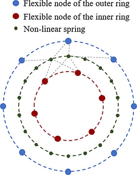
Forsch Ingenieurwes

Fig. 8 Polar histogram of the load cycles for each segment of both raceways of the upper row of the outer ring for a 20 years wind turbine life
time. The interval width of the bin counting is 25 MPa

Fig. 9 Damage factors for every
segment of all raceways of the
bearing calculated using the
Palmgren-Miner linear damage
hypothesis

cycles at the segment at 180° is greatly increased compared              raceways of the upper bearing row of the outer ring. The
to the segment at 60°. The temporal succession of the load               main wind direction is at 180°. Due to the dominant bending
cycles is strongly dependent on the pitch activity shown in              moment caused by the thrust, both raceways are loaded
Fig. 7c. This shows oscillations in the range of 0–20°.                  mostly one sided. The size of the loaded area is approx.
                                                                         205° for raceway OR 11 and 260° for raceway OR 12.
3.3 Local load counting                                                  The highest contact pressure occur on both raceways with
                                                                         a slight offset for the main wind direction.
First, the maximum pressure and number of load cycles                       In order to estimate the service life of the bearing, the
for each surface segment is determined for each of the 136               damage factor is determined according to Eq. 2. The dam-
time series. The individual time series are weighted based               age factors of each individual segment of the raceways is
on their probability of occurrence of its individual average             shown in Fig. 9. All of them show a clear highest loaded
wind speeds defined in DIN 61400 and extrapolated for                    zone and thus a clear preferred location of fatigue can be
a turbine lifetime of 20 years.                                          identified. This results from the dominant bending moments
   Fig. 8 shows the absolute frequency of load cycles as                 with a clear preferred load direction. However, the load
a function of contact pressure for each segment of the two               zones are wider than the load distribution of static load

                                                                                                                                   K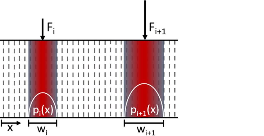
Forsch Ingenieurwes

cases shown in Fig. 5, which results from the consideration                  included in the article’s Creative Commons licence, unless indicated
                                                                             otherwise in a credit line to the material. If material is not included
of the shifting load direction. Similar to the load distri-
                                                                             in the article’s Creative Commons licence and your intended use is not
butions of the static load cases, it is noticeable that the                  permitted by statutory regulation or exceeds the permitted use, you will
individual raceways are loaded differently and thus there is                 need to obtain permission directly from the copyright holder. To view
a different risk of fatigue.                                                 a copy of this licence, visit http://creativecommons.org/licenses/by/4.
                                                                             0/.
   Naturally, the normal forces for the inner ring and outer
ring of one load diagonal are similar. The raceways of the
outer ring are concave and those of the inner ring are con-                  References
vex, so that the contact pressures for the same normal forces
are slightly higher. Since the diameter of the bearing is                     1. Leupold S (2019) Detailed load analyses of pitch bearings of
                                                                                 a 3 MW turbine based on multi body. In: Wind Energy Science
much bigger then the ball diameter this effect is compara-                       Conference Cork
tively small. Due to the movement of the inner ring up to                     2. Schwack F, Prigge F, Poll G (2018) Finite element simulation and
30°, the load is distributed over a larger area compared to                      experimental analysis of false brinelling and fretting corrosion. Tri-
the outer ring, which leads to a slightly reduced number of                      bol Int 126:352–362
                                                                              3. Bossanyi EA (2003) Individual blade pitch control for load reduc-
load cycles. These two effects lead to a different damage                        tion. Wind Energy 6:119–128
factor distribution of both raceways. Notable is a large over-                4. Fischer JPM (2019) Challenges for the design process of pitch bear-
lap of the damage factors of the raceways of one bearing                         ings and contribution of test benches. In: CWD Conference Aachen
row in the range of 50° and 250°. For assembly reasons,                       5. Harris T, Rumbarger JH, Butterfield CP (2009) Wind turbine design
                                                                                 guideline DG03: yaw and pitch rolling bearing life. In: NREL
there is a filler plug at one position of the raceway to fill the             6. Chen G, Wen J (2012) Load performance of large-scale rolling
raceways with rolling elements. This is a weak spot at the                       bearings with supporting structure in wind turbines. J Mech Des
raceway and should therefore be as unloaded as possible.                         134:1087
This is not possible if the load zones overlap strongly.                      7. Daidié A, Chaib Z, Ghosn A (2008) 3D simplified finite elements
                                                                                 analysis of load and contact angle in a slewing ball bearing. J Mech
                                                                                 Des 130:421
                                                                              8. Liu R, Wang H, Pang BT, Gao XH, Zong HY (2018) Load distri-
4 Conclusion                                                                     bution calculation of a four-point-contact slewing bearing and its
                                                                                 experimental verification. Exp Tech 42:243–252
                                                                              9. Krynke M, Kania L, Mazanek E (2011) Modelling the contact be-
In this paper a method was presented to simplify common                          tween the rolling elements and the raceways of bulky slewing bear-
FEM modeling approaches for the simulation of global load                        ings. KEM 490:166–178
distribution in blade bearings, so that an integration into an               10. Berroth J, Jacobs G, Kroll T, Schelenz R (2016) Investigation on
aeroelastic mbs wind turbine model is possible. It is able to                    pitch system loads by means of an integral multi body simulation
                                                                                 approach. J Phys Conf Ser 753:112002
calculate time series of the global load distribution for all                11. Dassault Systèmes Simulia Corp (ed) (2020x) SIMULIA user as-
raceways of the bearing. Thereby an average accuracy of                          sistance
6.5% could be achieved compared to the modeling in FEM.                      12. Deutsche Kommission Elektrotechnik, Elektronik, Information-
   By further data processing the number of load cycles for                      stechnik (2019) DIN EN IEC 61400-1 (VDE 0127-1), Winden-
                                                                                 ergieanlagen. Teil 1, Auslegungsanforderungen (IEC 61400-
individual areas of the blade bearing could be determined.                       1:2019): = Wind energy generation systems. Part 1, Design re-
It could be shown that the load distribution function for                        quirements (IEC 61400-1:2019), 61400th edn. VDE, Berlin
the individual segments is very different. Additionally, the                 13. Roy CR, Bampton MCC (1968) Coupling of substructures for dy-
areas with the highest risk for fatigue damage could be                          namic analyses. AIAA J 6:1313–1319
                                                                             14. Hertz HR (1882) Über die Berührung fester elastischer Körper und
identified. The modeling method could be used in the long
                                                                                 über die Härte. Universitätsbibliothek Johann Christian Sencken-
run to design rotor blade bearings against fatigue.                              berg), Frankfurt am Main
   Load cycles due to dynamic loads with stationary blade                    15. Lundberg G, Palmgren A (1947) Dynamic capacity of rolling bear-
bearings have not been considered so far. This could also be                     ings. Ingeniörsvetenskapsakademiens handlingar, vol 196. Gener-
                                                                                 alstabens Litografiska Anstalts Förl, Stockholm
taken into account in subsequent work. In addition, fatigue
                                                                             16. Leupold S, Schelenz R, Jacobs G (2020) Investigation of the indi-
criteria such as Fatemi—Socie [18] or Dang Van [19] could                        vidual load distribution of a blade bearing test rig by means of finite
also be applied on the simulation results.                                       element simulation. J Phys Conf Ser 1618:52056
                                                                             17. ISO International Organization for Standardization (2008) Rolling
Funding Open Access funding enabled and organized by Projekt                     bearings—Methods for calculating the modified reference rating
DEAL.                                                                            life for universally loaded bearings (ISO/TS 16281)
                                                                             18. Fatemi A, Socie DF (1989) Multiaxial fatigue: damage mechanisms
Open Access This article is licensed under a Creative Commons At-                and life predictions. In: Branco CM, Rosa LG (eds) Advances in
tribution 4.0 International License, which permits use, sharing, adapta-         fatigue science and technology. Springer, Dordrecht, pp 877–890
tion, distribution and reproduction in any medium or format, as long as      19. Van Dang K, Griveau B, Message O (1989) On a new multiaxial
you give appropriate credit to the original author(s) and the source, pro-       fatigue limit criterion: theory and application. EGF, vol 3, Mechan-
vide a link to the Creative Commons licence, and indicate if changes             ical Engineering Publication, London, 479–496
were made. The images or other third party material in this article are

K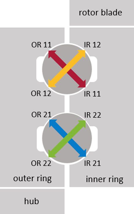
You can also read