CHILLED WATER AIR CONDITIONERS FOR IT COOLING - FROM 4 TO 25 kW CLOSE CONTROL AIR CONDITIONERS
←
→
Page content transcription
If your browser does not render page correctly, please read the page content below
IT COOLING
             CLOSE CONTROL AIR CONDITIONERS

                                   CHILLED WATER AIR
                                   CONDITIONERS FOR IT COOLING
                                   FROM 4 TO 25 kW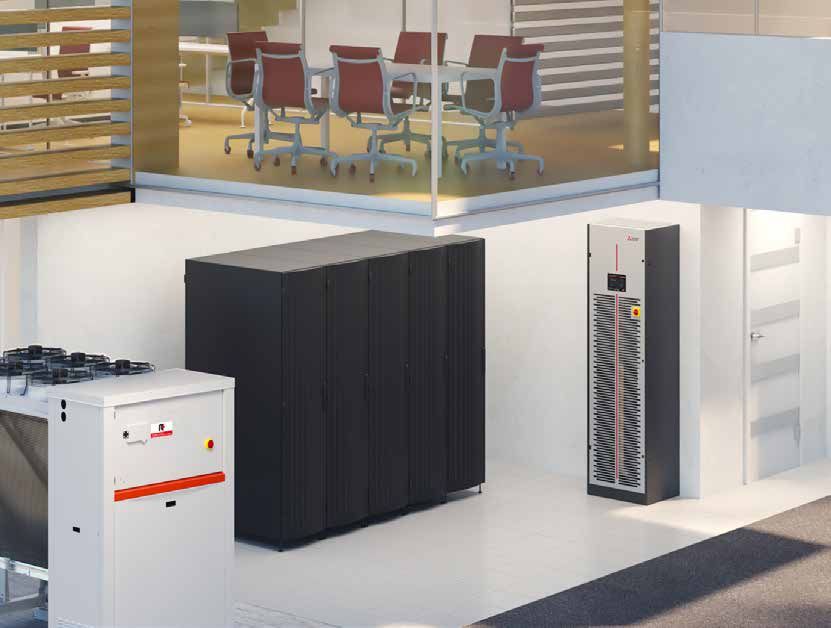
IT COOLING
               CLOSE CONTROL AIR CONDITIONERS

    Mitsubishi Electric presents w-MEXT:
    the new chilled water close control
    air conditioner designed for small
    and medium data centers.

02 / 03
02 / 03
The new chilled water unit is the result of
the highest quality and reliability standards
of Mitsubishi Electric applied to IT Cooling
applications.
w-MEXT is a guarantee of precise, reliant and
efficient air conditioning.
w-MEXT UNDER/OVER 06/07
Chilled Water Close Control Air Conditioner with downflow air delivery
w-MEXT DL
DISPLACEMENT VERSION 08/09
Chilled Water Close Control Air Conditioner with front air delivery
w-MEXT DF
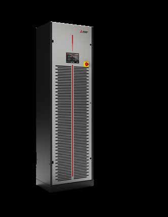
DUAL FLUID VERSION 10/11
Chilled water Close Control Air Conditioner with downflow
or upflow air delivery
IT COOLING
                         CLOSE CONTROL AIR CONDITIONERS

                                                       LAN FUNCTIONS: CONNECT UP TO 15
                                                       UNITS, WITH DYNAMIC MASTER

                                                     Advanced LAN logics manage up to 15 units and, in case
                                                     of a master unit failure, another master will be elected
                                                     automatically, for utmost dependability.

                                   ADVANCED SOFTWARE WITH
                                   USER-FRIENDLY INTERFACE

                                 New graphical user interface designed for a quick and
                                 intuitive navigation.

          ACTIVE REDUNDANCY

          Devoted group controls effectively share
          the load among all the connected units,
          leveraging on redundancy to reach
          higher efficiency.

04 / 05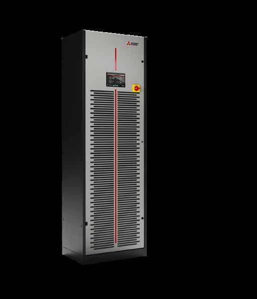
04 / 05

Higher efficiency, brilliantly embedded in a more
compact layout.

                                               HIGHER COOLING CAPACITY
                                               IN A COMPACT DESIGN

                                              New compact design that reduces the overall footprint and
                                              ensures the best kW/m3 ratio on the market.

                                  FLEXIBLE CHOICE OF AIR FLOW DIRECTION

                              Achieve any cooling requirement thanks to the possibility of
                              choosing between 3 types of air delivery:
                              Front, top and bottom.

                    MAINTENANCE-FREE EC FANS

                 Plug fans with EC electric motor:
                 4Maintenance-free motor
                 4Impeller in aluminium which greatly reduces of power
                   consumption.

 QUICK INSTALLATION AND EASY MAINTENANCE

 All components are integrated inside the unit for a
 plug and play installation.
 Totally removable panelling on the front to facilitate
 maintenance.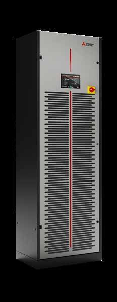
IT COOLING
                       CLOSE CONTROL AIR CONDITIONERS

                                       Chilled Water Close Control Air Conditioner
                                       with upflow or downflow air delivery

   w-MEXT WITH                                                w-MEXT WITH
   DOWNFLOW AIR DELIVERY                                      UPFLOW AIR DELIVERY
   The air distribution is from the bottom by                The air distribution is from the top of the unit
   means of the plenum between the building                  directly into the room by a plenum (or duct).
   floor and the raised floor.                               The supply air flow can be directed through the
   This solution is most favourable when the load            adjustable fins of the plenum grilles.
   is uniformly distributed in all areas of the room.

   TYPICAL INSTALLATION: DATA CENTERS WITH OR WITHOUT RAISED FLOOR

06 / 07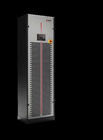
06 / 07

w-MEXT UNDER/OVER
MODEL                                                           6           9           11           13          16           22          26
SIZE                                                           F1          F1           F1           F1          F2           F2          F2
VERSION                                   (1)                  U/O         U/O          U/O          U/O         U/O          U/O         U/O
COOLING CAPACITY                          (2)
Total                                              kW         4.74        7.90         9.66         12.5         15.4        20.4         25.6
Sensible                                           kW         4.74        7.90         9.66         12.5         15.4        20.4         25.6
SHR                                       (3)                  1.0         1.0          1.0          1.0          1.0         1.0          1.0
“EC” SUPPLY FAN                                    No.          1           1            1            1            2           2            2
Air flow                                          m3/h        1500        2200         2500         2700         4300        5000         5400
Nominal external static pressure                   Pa          20          20           20           20           20          20           20
Maximum external static pressure                   Pa         201         471          384          268          277         362          246
Power input                               (4)      kW         0.07        0.21         0.32         0.45         0.40        0.68         0.95
COOLING COIL
Water flow rate                           (2)     m3/h        0.83        1.37          1.66        2.16         2.66        3.50         4.40
dP coil + valve                           (2)     kPa         37.1        61.1          32.2        55.7         46.5        80.2         108
Water content                                      l          1.6         2.3           3.1         4.7          4.4         5.9          8.9
UNIT ELECTRIC DATA
Electric panel power input                         kW         0.015       0.015        0.015        0.015       0.015        0.015       0.015
SOUND LEVEL ISO 3744                      (5)
Pressure level                                    dB(A)        42          56            58          60           53          60           62
Power level                                       dB(A)        58          72            74          76           69          76           78
AIR FILTERS                                        No.          1           1             1           1            2           2            2
Extended filtering surface                         m2         0.68        0.68          0.68        0.68         1.05        1.05         1.05
Efficiency (ISO EN 16890)                        COARSE       60%         60%           60%         60%          60%         60%          60%
ENERGY EFFICIENCY INDEX                   (2)
EER Energy Efficiency Ratio                      kW/kW        67.7        37.6          30.2        27.8         38.5        30.0         26.9
DIMENSIONS
Length                                            mm           600         600          600          600        1000         1000         1000
Depth                                             mm           500         500          500          500         500          500          500
Height                                            mm          1980        1980         1980         1980        1980         1980         1980
NET WEIGHT OVER                                   kg          103         109          116          120         163          173          181
NET WEIGHT UNDER                                  kg          110         118          126          130         173          183          191
CONNECTIONS
Cooling coil inlet/outlet – ISO 228/1-G              Ø         3/4”        3/4”         3/4”         1”         1+1/4”      1+1/4”       1+1/4”
Condensate                                (6)     Ø mm          19          19           19          19           19          19           19
Power supply wiring cable                 (7)   No. x mm2     3G1.5       3G1.5        3G1.5        3G1.5       3G1.5       3G1.5        3G1.5

The cooling capacity does not consider the supply fan motor thermal load

Notes:
1 U = Under, downflow / O = Over, upflow.                                 4   Corresponding to the nominal ESP=20Pa.
2 Gross value. Characteristics referred to entering air at 26°C-40% RH;   5   Sound pressure level on air return at 1m.
  Chilled water temperature 10-15°C – glycol solution 0%; ESP=20Pa.       6   Rubber pipe – referred to internal diameter.
3 SHR = Sensible cooling capacity / Total cooling capacity.               7   Minimum section of the power cable for units without accessories.
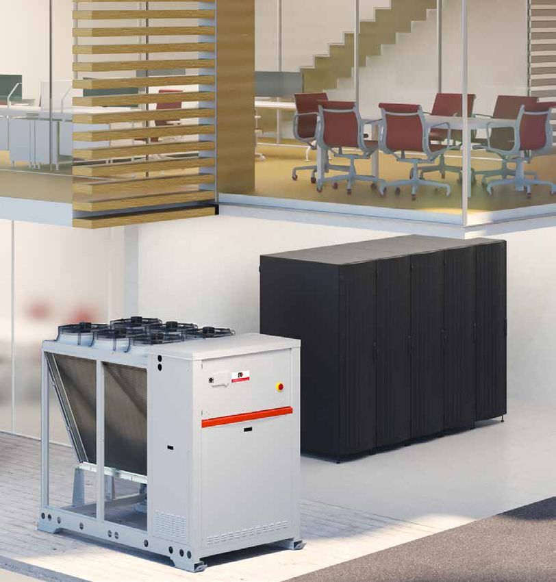
IT COOLING
                        CLOSE CONTROL AIR CONDITIONERS

                                      Chilled Water Close Control Air Conditioner
                                      with front air delivery

   w-MEXT WITH
   FRONT AIR DELIVERY

    Suitable for server racks with vented
    front and rear doors.
    Air suction is from the top of the unit
    and air delivery is horizontal into the
    cold aisle for cooling the racks
    The hot air is expelled from the racks at
    the top or from the back.

   TYPICAL INSTALLATION: DATA CENTER WITHOUT RAISED FLOOR

08 / 09
08 / 09 w-MEXT DL MODEL 6 9 11 13 16 22 26 SIZE F1 F1 F1 F1 F2 F2 F2 VERSION (1) DL DL DL DL DL DL DL COOLING CAPACITY (2) Total kW 4.68 7.64 9.32 10.8 14.9 19.2 21.8 Sensible kW 4.68 7.64 9.32 10.8 14.9 19.2 21.8 SHR (3) 1.0 1.0 1.0 1.0 1.0 1.0 1.0 “EC” SUPPLY FAN No. 1 1 1 1 2 2 2 Air flow m3/h 1050 1540 1750 1750 3010 3500 3500 Nominal external static pressure Pa 20 20 20 20 20 20 20 Maximum external static pressure Pa 127 304 347 316 302 334 314 Power input (4) kW 0.06 0.18 0.26 0.28 0.33 0.53 0.56 COOLING COIL Water flow rate (2) m3/h 0.79 1.33 1.62 1.87 2.56 3.30 3.74 dP coil + valve (2) kPa 36.5 57.7 30.2 42.6 44.0 72.4 81.3 Water content l 1.6 2.3 3.1 4.7 4.4 5.9 8.9 UNIT ELECTRIC DATA Electric panel power input kW 0.015 0.015 0.015 0.015 0.015 0.015 0.015 SOUND LEVEL ISO 3744 (5) Pressure level dB(A) 46 54 57 57 56 59 59 Power level dB(A) 62 70 73 73 72 75 75 AIR FILTERS No. 1 1 1 1 2 2 2 Extended filtering surface m2 0.68 0.68 0.68 0.68 1.05 1.05 1.05 Efficiency (ISO EN 16890) COARSE 60% 60% 60% 60% 60% 60% 60% ENERGY EFFICIENCY INDEX (2) EER Energy Efficiency Ratio kW/kW 78.0 42.4 35.8 38.6 45.2 36.2 38.9 DIMENSIONS Length mm 600 600 600 600 1000 1000 1000 Depth mm 500 500 500 500 500 500 500 Height mm 2120 2120 2120 2120 2120 2120 2120 NET WEIGHT kg 116 121 130 134 182 187 195 CONNECTIONS Cooling coil inlet/outlet – ISO 228/1-G Ø 3/4” 3/4” 3/4” 1” 1+1/4” 1+1/4” 1+1/4” Condensate (6) Ø mm 19 19 19 19 19 19 19 Power supply wiring cable (7) No. x mm2 3G1.5 3G1.5 3G1.5 3G1.5 3G1.5 3G1.5 3G1.5 The cooling capacity does not consider the supply fan motor thermal load Notes: 1 DL = Displacement air flow. 4 Corresponding to the nominal ESP=20Pa. 2 Gross value. Characteristics referred to entering air at 30°C-30% RH; 5 Sound pressure level on air return at 1m. Chilled water temperature 10-15°C – glycol solution 0%; ESP=20Pa. 6 Rubber pipe – referred to internal diameter. 3 SHR = Sensible cooling capacity / Total cooling capacity. 7 Minimum section of the power cable for units without accessories.
IT COOLING
                      CLOSE CONTROL AIR CONDITIONERS

                                     Chilled Water Close Control Air Conditioner
                                     with upflow or downflow air delivery

    w-MEXT WITH UPFLOW OR
    DOWNFLOW AIR DELIVERY
   The DUAL FLUID units allow the connection to two             This solution represents the perfect choice to provide
   independent chilled water loops. The control automatically   redundancy to the system or in case of heterogeneous
   manages the use of the two cooling coils.                    cooling source availability (e.g. chillers and dry coolers).

   TYPICAL INSTALLATION:
   DATA CENTERS WITH OR WITHOUT RAISED FLOOR

10 / 11
10 / 11 w-MEXT DF MODEL 9 16 SIZE F1 F2 VERSION (1) U/O U/O COOLING CAPACITY (2) Total kW 7,9 15,4 Sensible kW 7,9 15,4 SHR (3) 1.0 1.0 “EC” SUPPLY FAN No. 1 2 Air flow m3/h 2200 4300 Nominal external static pressure Pa 20 20 Maximum external static pressure Pa 445 241 Power input (4) kW 0.24 0.47 COOLING COIL Water flow rate (2) m3/h 1,36 2,65 dP coil + valve (2) kPa 61,1 46,5 Water content l 2.3 4.4 UNIT ELECTRIC DATA Electric panel power input kW 0.015 0.015 SOUND LEVEL ISO 3744 (5) Pressure level dB(A) 56 53 Power level dB(A) 72 69 AIR FILTERS No. 1 2 Extended filtering surface m2 0.68 1.05 Efficiency (ISO EN 16890) COARSE 60% 60% ENERGY EFFICIENCY INDEX (2) EER Energy Efficiency Ratio kW/kW 32,9 32,8 DIMENSIONS Length mm 600 1000 Depth mm 500 500 Height mm 1980 1980 NET WEIGHT OVER kg 116 177 NET WEIGHT UNDER kg 125 187 CONNECTIONS Cooling coil inlet/outlet – ISO 228/1-G Ø 3/4” 1+1/4” Condensate (6) Ø mm 19 19 Power supply wiring cable (7) No. x mm2 3G1.5 3G1.5 The cooling capacity does not consider the supply fan motor thermal load Notes: 4 Corresponding to the nominal ESP=20Pa. 1 U = Under, downflow / O = Over, upflow. 5 Sound pressure level on air return at 1m. 2 Gross value. Characteristics referred to entering air at 26°C-40% RH; 6 Rubber pipe – referred to internal diameter. Chilled water temperature 10-15°C – glycol solution 0%; ESP=20Pa. 7 Minimum section of the power cable for units 3 SHR = Sensible cooling capacity / Total cooling capacity. without accessories.
IT COOLING
                      CLOSE CONTROL AIR CONDITIONERS

   NEW TOUCH KEYBOARD
    A completely redesigned interface improves the user experience.

    The 7” touch screen display (opt.) with easy-to-read color graphics ensures the immediate
    visualization of the units’ status and provide simple alarms and event management.

   Dedicated menus show the main operating parameters like
   temperature, humidity, and ventilation.

                                                                  7” TOUCH DISPLAY
                                                 MULTILANGUAGE

                                                                                         INTUITIVE ICONS
                                                                                         for a better user experience

                                                                                         QUICK MENU ACCESS

                                                                                         REAL-TIME DISPLAY
                                                                                         of main operating variables

12 / 13
12 / 13
INNOVATIVE KIPLINK INTERFACE
Based on proprietary technology, KIPlink is an option that allows one to operate the unit
directly from a mobile device smartphone, tablet, or notebook.
EASIER ON-SITE OPERATION
View and change all parameters
thanks to an easy-to-understand
interface and dedicated tooltips.
Get devoted "help" messages for
alarm reset and troubleshooting.
REAL-TIME GRAPHS AND TRENDS
Monitor the immediate labour
status of main components.
View the real-time graphs of the
key operating variable trends.
DATA LOGGER FUNCTION
View history of events and use the
filter for a simple search. Enhance
diagnostics with data and graphs
of 10 minutes before and after
each alarm. Download all the data
for detailed analysis.IT COOLING
CLOSE CONTROL AIR CONDITIONERS
KIPLINK CONNECTIVITY
Keep in touch with your unit’s
control with KIPlink.
LOCAL WI-FI
LAN PORT
14 / 1514 / 15
WI-FI KEYBOARD
Close to the unit with MEHITS APP access
MOBILE DEVICE
01234567
Master 8910
Unit
iFXQ2
Direct access to the control is achieved by scanning
the QR-code positioned on the front side of the unit.
012345678910 iFXQ2
Master Unit
REMOTE CONTROL
In local network (LAN) of building with internet browser
BROWSER
With a simple Ethernet connection, it is possible to connect KIPlink to the facility LAN
and get full access to the unit’s control with a browser.
All the menus and functions are available with total security.www.melcohit.com/EN
You can also read