Cisco Extended Enterprise Design Guide non-fabric and SD-Access - February 2020 - Cisco Systems, Inc.
←
→
Page content transcription
If your browser does not render page correctly, please read the page content below
Cisco Extended Enterprise Design Guide
non-fabric and SD-Access
February 2020

                Cisco Systems, Inc.   www.cisco.com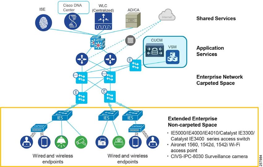
THE SPECIFICATIONS AND INFORMATION REGARDING THE PRODUCTS IN THIS MANUAL ARE SUBJECT TO CHANGE
WITHOUT NOTICE. ALL STATEMENTS, INFORMATION, AND RECOMMENDATIONS IN THIS MANUAL ARE BELIEVED TO BE
ACCURATE BUT ARE PRESENTED WITHOUT WARRANTY OF ANY KIND, EXPRESS OR IMPLIED. USERS MUST TAKE FULL
RESPONSIBILITY FOR THEIR APPLICATION OF ANY PRODUCTS.
THE SOFTWARE LICENSE AND LIMITED WARRANTY FOR THE ACCOMPANYING PRODUCT ARE INCORPORATED HEREIN BY
THIS REFERENCE. IF YOU ARE UNABLE TO LOCATE THE SOFTWARE LICENSE OR LIMITED WARRANTY, CONTACT YOUR
CISCO REPRESENTATIVE FOR A COPY.
The Cisco implementation of TCP header compression is an adaptation of a program developed by the University of California,
Berkeley (UCB) as part of UCB’s public domain version of the UNIX operating system. All rights reserved. Copyright © 1981,
Regents of the University of California.
NOTWITHSTANDING ANY OTHER WARRANTY HEREIN, ALL DOCUMENT FILES AND SOFTWARE OF THESE SUPPLIERS ARE
PROVIDED “AS IS” WITH ALL FAULTS. CISCO AND THE ABOVE-NAMED SUPPLIERS DISCLAIM ALL WARRANTIES, EXPRESSED
OR IMPLIED, INCLUDING, WITHOUT LIMITATION, THOSE OF MERCHANTABILITY, FITNESS FOR A PARTICULAR PURPOSE AND
NONINFRINGEMENT OR ARISING FROM A COURSE OF DEALING, USAGE, OR TRADE PRACTICE.
IN NO EVENT SHALL CISCO OR ITS SUPPLIERS BE LIABLE FOR ANY INDIRECT, SPECIAL, CONSEQUENTIAL, OR INCIDENTAL
DAMAGES, INCLUDING, WITHOUT LIMITATION, LOST PROFITS OR LOSS OR DAMAGE TO DATA ARISING OUT OF THE USE OR
INABILITY TO USE THIS MANUAL, EVEN IF CISCO OR ITS SUPPLIERS HAVE BEEN ADVISED OF THE POSSIBILITY OF SUCH
DAMAGES.
Any Internet Protocol (IP) addresses and phone numbers used in this document are not intended to be actual addresses and
phone numbers. Any examples, command display output, network topology diagrams, and other figures included in the
document are shown for illustrative purposes only. Any use of actual IP addresses or phone numbers in illustrative content is
unintentional and coincidental.
All printed copies and duplicate soft copies of this document are considered uncontrolled. See the current online version for
the latest version.
Cisco has more than 200 offices worldwide. Addresses, phone numbers, and fax numbers are listed on the Cisco website at
www.cisco.com/go/offices.

Cisco and the Cisco logo are trademarks or registered trademarks of Cisco and/or its affiliates in the U.S. and other countries. To view a list of Cisco trademarks, go to this URL:
www.cisco.com/go/trademarks. Third-party trademarks mentioned are the property of their respective owners. The use of the word partner does not imply a partnership relationship
between Cisco and any other company. (1721R)

                                                                                              2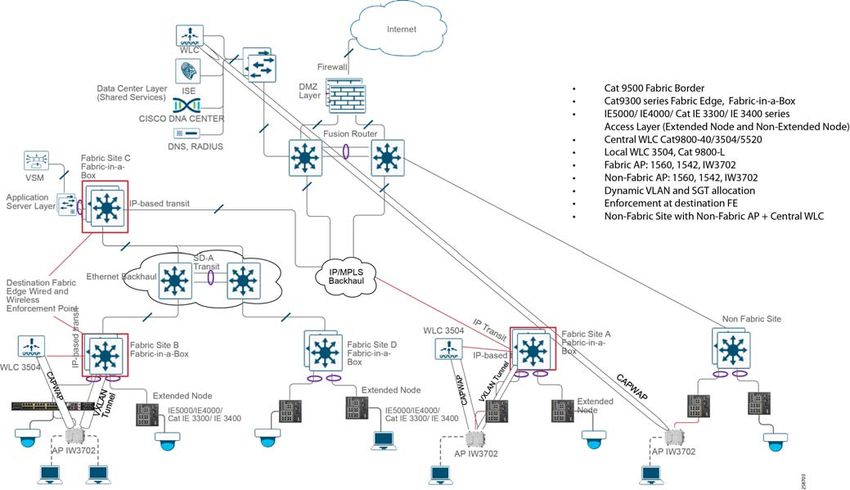
Contents
   Extended Enterprise Introduction . . . . . . . . . . . . . . . . . . . . . . . . . . . . . . . . . . . . . . . . . . . 1
   System Design . . . . . . . . . . . . . . . . . . . . . . . . . . . . . . . . . . . . . . . . . . . . . . . . . . . . . . . . 10
      Enterprise Network Overview . . . . . . . . . . . . . . . . . . . . . . . . . . . . . . . . . . . . . . . . . . 10
         Hierarchical Model . . . . . . . . . . . . . . . . . . . . . . . . . . . . . . . . . . . . . . . . . . . . . . . . 11
         Enterprise Access Layer . . . . . . . . . . . . . . . . . . . . . . . . . . . . . . . . . . . . . . . . . . . 11
         Enterprise Distribution Layer . . . . . . . . . . . . . . . . . . . . . . . . . . . . . . . . . . . . . . . . 12
         Enterprise Core Layer . . . . . . . . . . . . . . . . . . . . . . . . . . . . . . . . . . . . . . . . . . . . . 12
         Enterprise Endpoints . . . . . . . . . . . . . . . . . . . . . . . . . . . . . . . . . . . . . . . . . . . . . . 12
         Cisco DNA Center . . . . . . . . . . . . . . . . . . . . . . . . . . . . . . . . . . . . . . . . . . . . . . . . 13
         Cisco DNA Center Appliance . . . . . . . . . . . . . . . . . . . . . . . . . . . . . . . . . . . . . . . . 13
         Shared Services . . . . . . . . . . . . . . . . . . . . . . . . . . . . . . . . . . . . . . . . . . . . . . . . . 13
         SD-Access Overview . . . . . . . . . . . . . . . . . . . . . . . . . . . . . . . . . . . . . . . . . . . . . 13
         SD-Access Roles Summary. . . . . . . . . . . . . . . . . . . . . . . . . . . . . . . . . . . . . . . . . 14
         SD-Access Extended Nodes . . . . . . . . . . . . . . . . . . . . . . . . . . . . . . . . . . . . . . . . 15
         Enterprise Security Overview . . . . . . . . . . . . . . . . . . . . . . . . . . . . . . . . . . . . . . . . 15
         Security Attacks in IoT Devices . . . . . . . . . . . . . . . . . . . . . . . . . . . . . . . . . . . . . . 15
         Enterprise QoS Design Overview . . . . . . . . . . . . . . . . . . . . . . . . . . . . . . . . . . . . . 16
         Enterprise Wireless Network . . . . . . . . . . . . . . . . . . . . . . . . . . . . . . . . . . . . . . . . 17
      Extended Enterprise Network Design . . . . . . . . . . . . . . . . . . . . . . . . . . . . . . . . . . . . 17
         Extended Enterprise Design Considerations. . . . . . . . . . . . . . . . . . . . . . . . . . . . . 19
         Extended Enterprise Non-Fabric Design . . . . . . . . . . . . . . . . . . . . . . . . . . . . . . . 22
         Extended Enterprise SD-Access Design Overview. . . . . . . . . . . . . . . . . . . . . . . . 23
         Extended Enterprise Wireless Access . . . . . . . . . . . . . . . . . . . . . . . . . . . . . . . . . 28
         Choice of Wireless LAN Controller. . . . . . . . . . . . . . . . . . . . . . . . . . . . . . . . . . . . 33
      Extended Enterprise Security Policy Design. . . . . . . . . . . . . . . . . . . . . . . . . . . . . . . . 34
         The Rationale for Securing the Extended Enterprise Network. . . . . . . . . . . . . . . . 34
         Segmentation . . . . . . . . . . . . . . . . . . . . . . . . . . . . . . . . . . . . . . . . . . . . . . . . . . . 34
         TrustSec Overview . . . . . . . . . . . . . . . . . . . . . . . . . . . . . . . . . . . . . . . . . . . . . . . 35
         SGT tag mapping and propagation in a multi-site fabric environment. . . . . . . . . . 36
         Design the Security Policy in Extended Enterprise Network . . . . . . . . . . . . . . . . . 38
         Security Design Considerations for Non-Fabric Deployments . . . . . . . . . . . . . . . 41
         Security Design Considerations for SD-Access Deployments . . . . . . . . . . . . . . . 49
         Security Implementation Differences Between Fabric and Non-Fabric Deployments
             54

                                       Cisco Systems, Inc.          www.cisco.com

                                                               1
Managing Device Software Images . . . . . . . . . . . . . . . . . . . . . . . . . . . . . . . . . .                       54
   Extended Enterprise QoS Policy Design . . . . . . . . . . . . . . . . . . . . . . . . . . . . . . . . . .                    55
   Extended Enterprise Network Data Flows for Non-Fabric Deployments . . . . . . . . . .                                        59
   Extended Enterprise Network Data Flows for SD-Access Deployments . . . . . . . . . .                                         65
      SD-Access network Data Flow between Fabric Sites . . . . . . . . . . . . . . . . . . . . .                                67
   Extended Enterprise High Availability . . . . . . . . . . . . . . . . . . . . . . . . . . . . . . . . . . . .                69
   Extended Enterprise Scale and Dimensioning . . . . . . . . . . . . . . . . . . . . . . . . . . . . .                         70
Extended Enterprise Single Pane of Glass Management . . . . . . . . . . . . . . . . . . . . . . . .                             73
Summary . . . . . . . . . . . . . . . . . . . . . . . . . . . . . . . . . . . . . . . . . . . . . . . . . . . . . . . . . . .   75
Appendix A-Related Documentation . . . . . . . . . . . . . . . . . . . . . . . . . . . . . . . . . . . . . . .                  75
Appendix B—Glossary . . . . . . . . . . . . . . . . . . . . . . . . . . . . . . . . . . . . . . . . . . . . . . . . . .         76

                                                                  2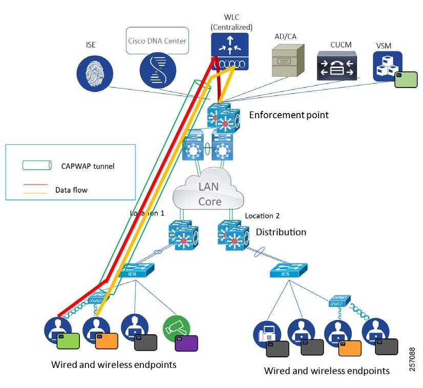
Cisco Extended Enterprise Design Guide
non-fabric and SD-Access
Extended Enterprise Introduction
Extended Enterprise helps you to transform your business by extending intent-based networking to the IoT Edge. The
Extended Enterprise Cisco Validated Design (CVD), which is documented in this Design Guide, provides a design
foundation for incorporating a broad set of technologies, features, and applications to help customers extend the
enterprise information technology (IT) services to outdoor spaces and production, storage, and distribution facilities.
CVDs provide the foundation for systems design and are based on common use cases or engineering system priorities.
Each guide has been comprehensively tested by Cisco engineers to help ensure a faster, more reliable, and fully
predictable deployment.
Extended Enterprise CVD
An enterprise has production, storage, distribution, and outdoor facilities. IT reach extends beyond the traditional
carpeted space to non-carpeted spaces as well. IT can now extend network connectivity, security policy, and
management to the outdoors, warehouses, and distribution centers-with the same network operating systems and
network management offering automation, policies, and assurance. The Cisco Digital Network Architecture (Cisco DNA)
is an architecture based on automation and analytics to deliver policy end-to-end at scale. Cisco DNA enables customers
to capture business intent and activate it network wide in the campus and in non-carpeted spaces where the operations
happen.
This CVD outlines the steps for both IT and operations teams to accomplish business goals by digitizing the operations
in the outdoor spaces of an enterprise. It includes design guidance for implementing Extended Enterprise use cases with
the customer's existing Cisco DNA Center using the Cisco industrial networking portfolio.
References
To learn more about Extended Enterprise solutions, please visit:
https://www.cisco.com/go/extendedenterprise
https://www.cisco.com/go/iotcvd
Scope and Audience for this Document
This design guide provides an overview of the requirements driving the evolution of Extended Enterprise network designs
followed by a discussion of the latest technologies and designs that are available for building an extended network to
address those requirements. It is a companion to the associated Design and Deployment Guides (DDGs) for enterprise
networks, which provide configurations explaining how to deploy the most common implementations of the designs as
described in this guide. The intended audience are technical decision makers who want to understand the Cisco
Extended Enterprise offerings, the technology options available, and the leading practices to design the best network for
the needs of an extended enterprise.
This guide provides:
A reference design for extending the enterprise network with the Cisco DNA Center to non-carpeted spaces
Design of a centralized policy matrix using the Cisco DNA Center and the Identity Service Engine (ISE)
Cisco Systems, Inc. www.cisco.com
1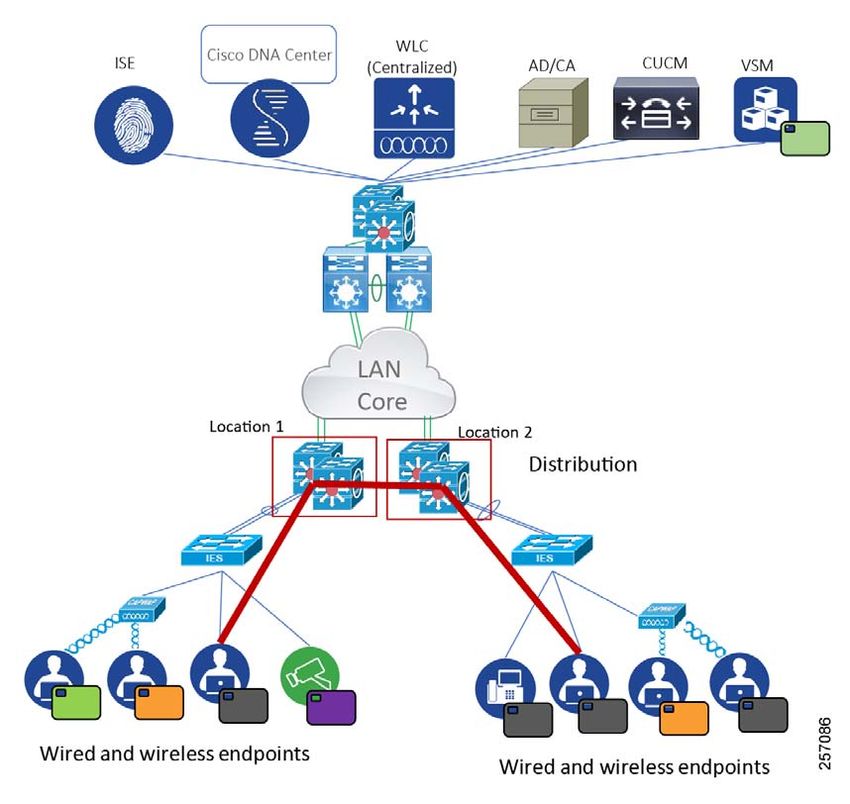
Cisco Extended Enterprise Design Guide non-fabric and SD-Access
Extended Enterprise Introduction
Design and implementation of security segmentation for Extended Enterprise endpoint points such as cameras,
phones, laptops, and others.
Guidance on how to deploy and manage extended nodes - IE switches using the Cisco DNA Center.
For the associated deployment guides, related design guides, and white papers, see the following pages and Appendix
A-Related Documentation, page 75:
Cisco Enterprise Networking design guides at the following URL:
— https://www.cisco.com/go/designzone
Cisco IoT Solutions design guides at the following URL:
— https://www.cisco.com/go/iotcvd
Cisco Extended Enterprise Solutions overview, design and implementation guides at the following URL:
— https://www.cisco.com/go/extendedenterprise
The Value of the Extended Enterprise CVD to an Organization
As your organization grows, you must plan how to extend the enterprise network infrastructure to support the network
requirements of non-carpeted spaces. Planning, testing, and implementing various components and shared services for
an extended network poses a large challenge for organizations. In contrast, by using the Extended Enterprise CVD's
modular approach that tests and validates the foundation infrastructure, security, automation, assurance, and shared
services, organizations can reduce costs, risks, and operational issues and increase deployment speed.
An organization can benefit in the following ways by deploying the Extended Enterprise CVD:
Summarized and simplified design choices for accelerating design, deployment, and operation of the extended
networks
Simplicity through a single pane of glass (SPOG) for managing carpeted and non-carpeted spaces-including design,
policy enforcement, provisioning, and assurance for all network devices
Intent-based policies for IoT end points
Reduced cost of zero touch deployment (ZTD) through Plug and Play (PnP) for provisioning Industrial Ethernet (IE)
switches and outdoor wireless access points (APs)
Scalability provided by intent-based networking, assurance, guided remediation, and troubleshooting
High availability and reliability in non-carpeted spaces for resilient operations
Business Overview
Introduction to Cisco® Digital Network Architecture (DNA)
The top-of-mind issue in IT organizations today is digital transformation. The enterprise network is at the heart of every
digital transformation. Most enterprises have thousands of users, thousands of applications, and often tens of thousands
of network-enabled devices. Global IP traffic is projected to nearly triple from 2017 to 2022; additionally, 10 billion more
Internet of Things (IoT) devices are expected to come online within the same time frame (according to Cisco Visual
Networking Index™ forecasts1).
Each year various new devices in different form factors with increased capabilities and intelligence are introduced and
adopted in the market. A growing number of machine-to-machine (M2M) applications, such as smart meters, video
surveillance, healthcare monitoring, transportation, and package or asset tracking, are providing a major contribution to
the growth of devices and connections. By 2022, M2M connections will be 51 percent of the total devices (according to
Cisco Visual Networking Index™ forecasts).
1. https://www.cisco.com/c/en/us/solutions/service-provider/visual-networking-index-vni/index.html
2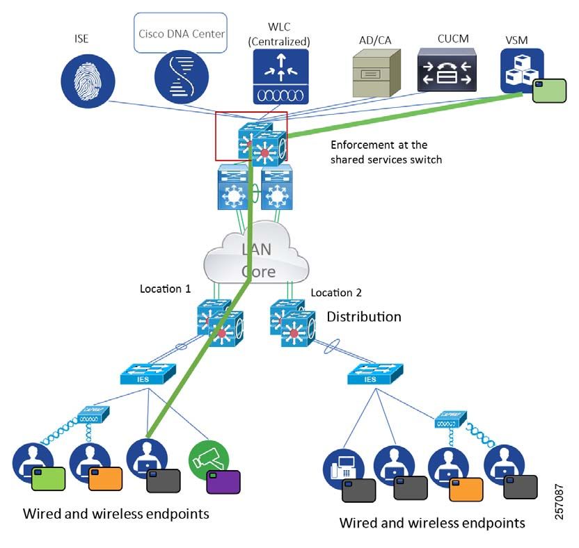
Cisco Extended Enterprise Design Guide non-fabric and SD-Access
Extended Enterprise Introduction
Manual management of network operations is becoming increasingly untenable for IT departments, a challenge that is
exacerbated by the myriad inconsistent and incompatible hardware and software systems and devices in the enterprise.
In contrast, an intent-based, closed-loop architecture that includes automation and analytics platforms significantly frees
up IT time and resources, and allows them to be reallocated to driving strategic projects and digital transformation. Cisco
DNA Center™ is the platform that introduces automation and analytics into the enterprise network. Cisco DNA Center is
a single pane of glass for designing a network, provisioning the network, administering policy for the network, and
assuring the network.
The primary purpose of the automation platform in Cisco DNA Center is to “talk” to the network-in other words, to
translate the expressed business intent into optimal platform-specific configurations on the network devices. In a
complementary manner, the primary role of the analytics platform is to “listen” to the network, specifically to gather,
correlate, and make sense of all the network telemetry generated by network devices, in order to correlate this data with
the expressed business intent.
The Cisco Digital Network Architecture provides a road map to digitization and a path to realize immediate benefits of
network automation, assurance, and security. Cisco Software-Defined Access (SD-Access) is the Cisco DNA evolution
from traditional campus LAN designs to networks that directly implement the intent of an organization. SD-Access is
enabled with an application package that runs as part of the Cisco DNA Center software for designing, provisioning,
applying the policy, and facilitating the creation of an intelligent campus wired and wireless network with assurance.
Fabric technology, an integral part of SD-Access, enables wired and wireless campus networks with programmable
overlays and easy-to-deploy network virtualization, permitting a physical network to host one or more logical networks
as required to meet the design intent. In addition to network virtualization, fabric technology in the campus network
enhances control of communications, providing software-defined segmentation and policy enforcement based on user
identity and group membership.
SD-Access support for extended nodes is about extending the enterprise network to provide more connectivity to
non-carpeted spaces of an enterprise. The products for extending the enterprise network are different, but the
processes and techniques to build it out are the same.
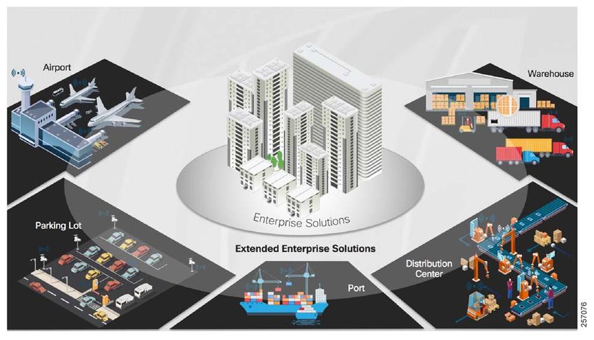
Introduction to Extended Enterprise
The Extended Enterprise is where business operations happen-outdoor and non-carpeted spaces such as distribution
centers, warehouses, ports, or campus parking lots. Enterprises are looking to innovate and differentiate their offerings
by digitizing their operations beyond the traditional carpeted spaces. However, the initiatives on digitizing the operations
require network connectivity to be extended beyond the traditional air-conditioned spaces-to connect and manage IoT
devices, as well as deploying traditional enterprise end devices in outdoor and non-carpeted environments.
Customers require ruggedized Ethernet switches, routers and outdoor wireless APs to extend network connectivity to
non-carpeted spaces because of the harsh environments in outdoor spaces. In addition, security concerns for extended
networks should be addressed with consistent network policies. Customers require speed with agility to deploy and
manage networks in non-carpeted spaces while meeting the required compliance and regulatory goals, as illustrated in
Figure 1.
With digitization, enterprises are challenged to improve operational efficiency, deliver new service offerings, and increase
customer satisfaction. Delivering these business outcomes require a new, intent-based approach to networking in order
to manage the challenges of scale and security faced by the enterprise.
3
Cisco Extended Enterprise Design Guide non-fabric and SD-Access
Extended Enterprise Introduction
Figure 1 Extended Enterprise Objectives and Challenges
By connecting the Extended Enterprise to your core IT managed networks, you can:
Unleash the power of data from the edge to gain operational insights and improve processes and systems
Enable new digital experiences for your customers and increase customer satisfaction
Generate new incremental revenue for your business by digitizing your extended enterprise
Manage the entire enterprise network centrally and reduce operating expenses (OpEx)
Simplify, secure, and control IT-run industrial Extended Enterprise environments
4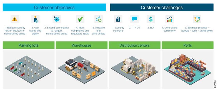
Cisco Extended Enterprise Design Guide non-fabric and SD-Access

Extended Enterprise Introduction

Extended Enterprise Network Requirements
      Many enterprises have warehouses, parking lots, and distribution centers; typically, more than one. Because of dust,
      heat, cold, dampness, and humidity, these outdoor facilities require ruggedized networking products. Enterprises want
      to replicate operations as much as possible to save on capital expenditures and operational costs.

      Figure 2    Extended Enterprise Use Cases

      With the explosive growth in IoT and industrial devices connecting to the core network, combined with the need to secure
      against threats and secure network access, IT must oversee, manage, and secure extended spaces, and ensure business
      integrity. Therefore, network teams are being asked to extend network connectivity beyond the air-conditioned spaces
      more and more in order to connect and manage IoT devices as well as traditional enterprise end devices being deployed
      in outdoor or extreme-temperature environments. The overall goal is to drive efficiency and reduce OpEx in the
      non-carpeted spaces with industrial networking.

      Outdoor facility networking requirements need IT to be able to quickly provision devices and services, manage the
      network device inventory, manage the software versions of the network devices, and do it all securely.

      Most enterprises also have a need to enable outdoor connectivity to campus parking lots in adverse weather conditions
      for assets such as IP cameras, video encoders, and Wi-Fi APs.

      Enterprises that have distribution centers need reliable network operation without air conditioning costs. Operational
      efficiency of the connected equipment is of key interest to distribution centers and IT executives. Consolidation of
      warehouse and distribution center networks into one centrally-managed network greatly simplifies Extended Enterprise
      networks managed by IT through the Cisco DNA Center and SD-Access fabric. The Cisco DNA Center can provide a
      SPOG for managing enterprise and Extended Enterprise networks.

                                                              5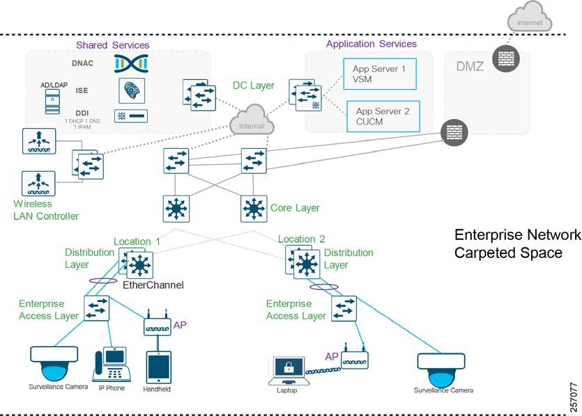
Cisco Extended Enterprise Design Guide non-fabric and SD-Access

Extended Enterprise Introduction

      This Extended Enterprise Design Guide addresses the network requirements described below.

      Flexible Industrial Ethernet Network Foundation for Harsh Environments in Non-Carpeted Spaces
      Extended enterprise environments require network devices to operate in very hot (+70°C), very cold (-40°C), and dusty
      environments. Extended enterprise network devices need to be hardened for vibration, shock and surge, and noise
      immunity while adhering to overall IT network design, compliance, and performance requirements.

      Extended enterprise deployments in outdoor spaces, warehouses, and distribution centers require high-speed gigabit
      Ethernet connectivity in a compact form factor modular design, which is flexible for rapid expansion, bandwidth, and
      capacity planning to grow with the needs of operations.

      The industrial Ethernet network in non-carpeted spaces must comply with stringent industry standards for
      electromagnetic emissions, immunity, and safety.

      Cisco is the leading manufacturer of managed Industrial Ethernet switches at both Layer 2 and Layer 3, including >1 GB
      Ethernet ports. Cisco Industrial Ethernet switches support industrial characteristics such as DIN rail/rack mount/
      embedded form factors, extended operating temperatures, passive cooling, redundant components, industrial
      connectors, higher IP rating and several industrial network protocols. The switches also offer copper, fiber, and Power
      over Ethernet (PoE) port options. The platform provides the flexibility to adapt your growing network connectivity needs
      and helps to future-proof your investments.

      Cisco Industrial Ethernet switches can be managed through Cisco DNA Center platform, enabling IT to extend
      Intent-Based Networking and single security policy framework from the data center, through the enterprise network, to
      the ruggedized network.

      Extend Secure Connectivity to Outdoor Non-Carpeted Spaces for Users, Traditional IT Endpoints, and Things
      Enterprises have an ever-increasing requirement to securely connect IoT endpoints (things) in outdoor environments. The
      Cisco IE switching products are a great example of providing networking connectivity outside the wiring closet. These
      devices are deployed outdoors, in the ceiling, or in roadside cabinets. The extended access network should have the
      ability to support high-density industrial PoE/PoE+ providing in-line power for devices such as IP cameras and phones,
      badge readers, and Wireless APs.

      Most Extended Enterprise environments need IP video surveillance for security, APs for mobility, IP phones, desktop PC
      access, and networked printers--the same types of networked end devices that you would find within an air-conditioned
      office building.

      Capture and Translate Business Intent into Network Policies and Consistently Enforce the Policies across the Entire
      Network
      The Cisco 2017 Security Capabilities Benchmark Study found that nearly a quarter of the organizations that have suffered
      an attack lost business opportunities as a result. Four in ten said those losses are substantial. One in five organizations
      lost customers due to an attack, and nearly 30 percent lost revenue. Because they are common targets for security
      attacks, hardening the security of the network devices is essential.

      Intent-based networking (IBN) enables conventional practices that require the alignment of manually-derived individual
      network-element configurations to be replaced by controller-led and policy-based abstractions that easily enable
      operators to express intent (desired outcome) and subsequently validate that the network is doing what they asked of it.
      The controllers, which provide the automation and controls that make up the IBN, reduce risk by ensuring that security
      policies are being applied consistently across the extended network, and help ensure that policies are compliant with
      Extended Enterprise business requirements. They capture and translate business intent into network policies and activate
      them across the infrastructure.

      Operations intent-based groupings provide consistent policy and access independent of network topology in carpeted
      and non-carpeted spaces. Creating group-based policies leveraging attributes such as device type and location
      provides a much easier and scalable way to manage security policies for access control across the extended enterprise.
      Security Group Tags (SGTs) that are assigned from group-based policies can provide micro-segmentation within a virtual
      network.

                                                                   6
Cisco Extended Enterprise Design Guide non-fabric and SD-Access
Extended Enterprise Introduction
Simple, Centralized Network Management across the Carpeted and Non-Carpeted Spaces
Managing network operations manually is becoming increasingly untenable for IT departments, a challenge that is
exacerbated by the myriad inconsistent and incompatible hardware and software systems and devices in the enterprise.
Adding more devices to the extended network increases the management complexity. To drive simplicity, it is important
for enterprises to have a SPOG for designing, provisioning, and administering policies, and ensuring the network
consistently across carpeted and non-carpeted spaces. The goal is for network engineers to see everything going on in
the network, everywhere in the world, from one interface.
To drive business growth and innovation, a complete network management system that is centralized across carpeted
and non-carpeted spaces is required. Customers need a network management system that can automate the
deployment, connectivity, and lifecycle of your infrastructure and proactively maintain the quality and security of your
applications so that IT staff can focus on networking projects that enhance your core business.
Reduce Day Zero Deployment Time of Networks in the Non-Carpeted Spaces
Many Extended Enterprise environments do not have an on-site IT network engineer and the extended network must be
managed remotely. IT staff need to be able to quickly deploy new devices and new services. Time is critical and
expensive since the installer is likely an hourly contractor or has to travel from the corporate office to be on site.
An extended network should automatically remotely provision and onboard new network devices with minimal network
administrator and field personnel involvement. A workflow should define a network device provisioning process that
includes a series of actions such as installing a software image, applying a device configuration, renumbering a switch
stack, or specifying a switch stack license.
The Cisco DNA Center provides the PnP feature for zero-touch network deployment in non-carpeted spaces. With PnP,
you should be able to ship new industrial networking devices directly to the warehouse or a distribution center where a
local person will power it up. The switch will automatically connect to the Cisco DNA Center to retrieve the correct code
based on its serial number. PnP can significantly reduce the time for provisioning the extended network and for spending
on upgrades by automating the steps.
Compliance to Latest Security Patches of Industrial Networking
Network administrators are always challenged when it comes to upgrading their network, whether it is planned or
ad-hoc, in order to remediate a security vulnerability. As Extended Enterprise networks become more and more complex,
it becomes even harder to manage the software versions and deploy the new security patches when they become
available.
To determine whether software image standards comply with the deployed devices, it is imperative that device auditing
is automated and flag devices that are not compliant with standardized software image updates. Patching provides small
updates to react quickly to security fixes. The Cisco DNA Center simplifies the version management and routine
deployment of software updates to your network devices by helping customers plan, schedule, download, monitor, and
standardize software image updates.
Secure Outdoor Wireless Connectivity in Non-Carpeted Spaces
Extended enterprise networks require rugged outdoor Wi-Fi coverage for their outdoor clients. Wireless video cameras
monitor security. In large installations, the roaming functionality provided by multiple APs enables wireless users to move
freely throughout the facility while maintaining uninterrupted access to the network. The security requirements described
above should be consistent for wired Ethernet or wireless LAN.
With the latest 802.11ac Wave 2 technology, transmitting data at speeds beyond 1Gbps can accommodate growth in
wireless usage in outdoor spaces. One key part of 802.11ac Wave 2 technology that can help keep extended networks
ahead of the capacity crunch is Multi-user multiple-input and multiple-output (MU-MIMO). MU-MIMO allows an access
point to transmit to multiple clients at the same time instead of sending data to a single client at a time. These parallel
transmissions improve RF efficiency when client devices also support 802.11ac Wave 2.
7Cisco Extended Enterprise Design Guide non-fabric and SD-Access
Extended Enterprise Introduction
Cisco outdoor APs can be deployed as traditional access points or wireless mesh access points. Cisco Flexible
Antenna-Port technology uses software that is configurable for either single- or dual-band antennas. It allows customers
to use the same antenna ports for either dual-band antennas to reduce footprint or single-band antennas to optimize
radio coverage.
Simplify Deployment of QoS across the Extended Network
Extended networks can have a variety of business needs for Quality of Service (QoS). A safety and security operations
business may want to ensure a high-quality images for video cameras in the campus parking lots for video surveillance.
A distribution center may want to guarantee voice quality to meet enterprise standards.
The principle goal of a QoS policy for an extended network is to express the strategic QoS policy with maximum fidelity
and to generate platform-specific configurations. The Cisco DNA Center can simplify the deployment of QoS across the
extended enterprise.
Network Assurance-Visibility and Analytics on the Health of Industrial Network Devices
As networks grow in complexity, research show that network IT spends four times more time collecting the data than
analyzing the problem. In a world of device explosion and extended networks, this problem will only get worse. The
traditional response to onboarding incidents involves many manual steps, such as checking user credentials and DHCP
issues, and radio channel analysis, all of which adds to a high incident response time.
It is imperative an extended network has onboarding analytics across the entire network-both wired and wireless. Cisco
DNA Center Assurance uses anomaly-driven telemetry from 240+ real-time events coming from the wireless and wired
infrastructure on client onboarding that helps to evaluates the time to connect and possible stages for the delay. Any
delays in onboarding will be spotted and flagged by the Cisco DNA Center before the user has a chance to report the
problem.
Guided Remediation and Troubleshooting of Issues in the Extended Network
A very common challenge facing IT is isolating problems; in other words, IT personnel are faced with finding the needle
in a haystack. Further, unlike wired networks with their relative predictability, wireless networks are easily impacted by
more dynamic and fluctuating variables (such as Received Signal Strength Indicators and Signal-to-Noise Ratios). As
such, the challenge is exacerbated and can be more aptly described as trying to find a randomly appearing and
disappearing needle within a haystack! Issues come and go as more rogue devices come online. And if IT cannot
replicate such transient and fluctuating Wi-Fi issues, they cannot resolve them.
To guide remediation to a network issue, it is important to have a holistic view of users, clients, applications, and the
network with full context of the interactions between these elements. Furthermore, troubleshooting is not limited to
currently occurring issues, but Cisco DNA Center allows operators to “go back in time” via a time-series database of all
measured data points to diagnose and root-cause issues that have occurred in the past.
Cisco DNA Center Assurance provides a 14-day look back, giving the full contextual network data and interrelationships
and eliminating the need to replicate the issue in order to identify and resolve a problem. All information on the user or
the network device changes to the selected time.
Extend Shared Services to Extended Networks in Non-Carpeted Spaces
Most extended network deployments require access to shared services in the form of identity services, Dynamic Host
Configuration Protocol (DHCP), Domain Name System (DNS), IP Address Management, IP voice/video collaboration
services, application servers, and data center applications. It is important that these shared services are designed
correctly in order to preserve the isolation between different virtual networks sharing those services. Most deployments
require shared services across all virtual networks and other inter-virtual network communication.
High Availability, Reliability, and Scale of Extended Networks to Meet Operational Needs
Most Extended Enterprise network deployments have to cater to the needs of business-critical operations. Therefore,
extended network designs should enable end-to-end redundancy and high availability. The design should extend
geographical scalability where longer-distance connectivity is required.
8Cisco Extended Enterprise Design Guide non-fabric and SD-Access
Extended Enterprise Introduction
Example Use Case: Secure Connectivity for Campus Parking Lots
Many enterprise campuses have a number of parking lots to cater to the needs of their employees and guests. Campus
parking lots are typically monitored by safety and security operations teams responsible for theft prevention and for
ensuring safety of the employees and the guests. Digitizing the campus parking lots can help improve the overall
experience of the employees such as a mobile application tracking a free electric vehicle charging station near a campus
building. In addition, enabling secure outdoor wireless connectivity in the campus parking lots is desirable for business
collaboration.
The safety and security operations would like to have IP video surveillance cameras installed in the parking lots to ensure
the safety of employees and the guests entering or leaving the parking lot. Live streaming and video retention to comply
with local policies is critical for the safety and security operations agents to monitor from remote locations. Appropriate
QoS policies for campus or WAN network bandwidth allocation is needed for live video monitoring by remote agents.
How can we address such network requirements in outdoor spaces where network devices need to be able to work in
ruggedized spaces, connecting PoE-powered end devices such as IP cameras, phones, wireless access points, sensors,
and more? The network devices should be hardened to withstand harsh environments, temperature ranges (-40°C to
+75°C), vibration, shock, surge, and electrical noise. More importantly, the network devices should comply to the safety
standards and certifications with high Mean Time Between Failures (MTBF).
The Cisco IE switches, routers, and outdoor wireless APs have been designed specifically to withstand the harshest
industrial environments in a compact, form-factor, modular switch that is purpose-built for a wide variety of Extended
Enterprise applications, such as campus parking lot environments. The IE switches provide bandwidth and capacity to
grow with a customer's networking needs: full gigabit Ethernet interfaces to connect high-speed wireless APs,
high-definition (HD) IP cameras, and programmable logic controllers (PLCs).
An employee or guest's mobile device or a parking lot IoT sensor, when compromised by malware, may change network
communication behavior to propagate and infect other endpoints. Cisco ISE and Cisco SD-Access can address the need
for complete isolation between the IoT sensors, traditional IT endpoints such as IP cameras, and the enterprise network
by using macro segmentation, and adding devices into different overlay networks, thus enabling the isolation.
Flexible policy creation allows the ability to have groups of device types and user roles to restricted communication within
a group or amongst groups. By extending the secure connectivity to campus parking lots, IT should be able to leverage
the existing investments in their campus network for non-carpeted spaces.
The primary solution components are Cisco IE switches, outdoor APs, Cisco DNA Center, Cisco ISE, and the Cisco DNA
Assurance Engine. The Cisco DNA Center is the primary application for designing, defining policy, and provisioning the
network infrastructure-a SPOG across the carpeted and non-carpeted spaces of an enterprise. The ISE provides the
security behind the solution. The Cisco DNA Assurance Engine gives insight into network and user performance.
Deploying the intended outcomes for the needs of the Extended Enterprise operations is simplified using the automation
capabilities built into the Cisco DNA Center, and those simplifications span the wired and wireless domains.
9Cisco Extended Enterprise Design Guide non-fabric and SD-Access
System Design
System Design
Extending the enterprise is about leveraging already existing campus networks and adding connectivity to outdoor and
non-carpeted spaces using the Cisco industrial networking portfolio. The design addresses both extended enterprise
SD-Access as well as non-fabric deployments. Most concepts discussed in the design apply to both. Differences and
specific details will be highlighted when applicable.
This chapter, which discusses the end-to-end system design starting with an overview of the enterprise network and
followed by a detailed design for the Extended Enterprise network, includes the following major topics:
Enterprise Network Overview, page 10
Extended Enterprise Network Design, page 17
Extended Enterprise Security Policy Design, page 34
Extended Enterprise QoS Policy Design, page 55
Extended Enterprise Network Data Flows for Non-Fabric Deployments, page 59
Extended Enterprise Network Data Flows for SD-Access Deployments, page 65
Extended Enterprise High Availability, page 69
Extended Enterprise Scale and Dimensioning, page 70
Enterprise Network Overview
The enterprise could be a geographically-distributed organization spread across multiple sites and campuses. The
overall enterprise network is managed by the Cisco DNA Center. Wireless and wired connectivity is provided across the
enterprise. Several types of hosts or endpoints such as video surveillance cameras, Wi-Fi clients, IP phones, and video
terminals are connected to the enterprise network for different services. The application services are centrally hosted
and have restricted access to authorized clients. Enterprise-wide shared services such as the DHCP server, IP Address
Management (IPAM), DNS, and ISE are hosted in the data center along with the Cisco DNA Center. Enterprise internet
connectivity is protected by the firewall. Internet access is available across the organization. The Cisco DNA Center
requires internet access for regular cloud updates.
The enterprise network, depending on the size and its needs, can be a two-layered or three-layered architecture. The
design considerations and design details for the Extended Enterprise apply equally well to both architectures. For
illustration purposes, a three-layered architecture, as shown in Figure 3, is considered to be the Enterprise Network
Architecture. The three layers are the core, distribution, and access. The following section describes a high-level
overview of these hierarchical layers and respective roles.
10Cisco Extended Enterprise Design Guide non-fabric and SD-Access
System Design
Figure 3 Enterprise Network Design
Hierarchical Model
The hierarchical network design model breaks the design into modular layers. Each layer implements specific functions,
thus helping simplify network design, deployment, and management, and also making the network scalable. Modular
structuring of the network also improves scalability and facilitates resiliency through improved fault isolation. Cisco
Enterprise Network Design CVDs cover these architectures (please see Appendix A-Related Documentation, page 75).
The three-layered architecture consists of the following:
Access Layer-Provides endpoints and users direct access to the network.
Distribution Layer-Aggregates access layers and provides connectivity to services.
Core Layer-Provides connectivity between distribution layers for large LAN environments. Capacity, density, and
features are the primary differences that drive what platform to select.
Enterprise Access Layer
The access layer, which is placed at a close proximity, provides connectivity to user devices and clients that are
connected to the network. The access layer provides both wired and wireless connectivity and contains features and
services that ensure security and resiliency for the entire network. Typically incorporating Layer 2 switches, it provides
different functionalities that include:
Layer 2 connectivity - fiber or copper and wireless to endpoints (e.g., laptops, cameras, and IP phones)
Can provide PoE power to wired endpoints
Enforces security by end user authentication and security policy enforcement
11Cisco Extended Enterprise Design Guide non-fabric and SD-Access
System Design
Acts as a QoS trust boundary (Classification, Marking)
Labels packets to enforce segmentation
Enterprise Distribution Layer
The distribution layer has several important services. It aggregates access layers and provides connectivity services. It
aggregates traffic from several access layer switches and provides uniform transportation. The important features
provided by distribution layer devices include:
Layer 3 connectivity to the core layer and Layer 2 into the access
Broadcast domain control
Aggregation of access layer traffic and provide connectivity services
Routing between LAN and VLANs
Route aggregation and summarization
Policy-based security and QoS
Scalability, fault domain isolation, high availability, and resiliency
Typically, a Layer 3 router or a Layer 3-capable switch is used
It can act as the fog computing platform
Enterprise Core Layer
A third layer serving as the backbone and central point of the network is often needed while catering to a large distributed
network spread across multiple geographically-dispersed buildings. Having a distribution layer switch in each of the
buildings helps to reduce costly fiber runs. As networks grow beyond three distribution layer switches, organizations
should use a core layer to optimize the design.
The key value-adds and features of the core layer include:
Uninterrupted connectivity to the distribution layer
Provides site-wide redundancy, fault tolerance, resiliency, and reliability having Layer 3 connectivity to and from the
core layer
Provides high-speed switching (in other words, fast transport) to support a large-scale network
Very low latency, avoiding CPU-intensive packet manipulations
Non-disruptive in-service upgrades
Enterprise Endpoints
The devices that connect to the enterprise access switch are called endpoints. Endpoints may be either wired clients
that directly connect to the access switch node or wireless clients attached to an AP. Endpoints could be a security
camera, IP phone, user laptop, tablet, or mobile phone connected to the network. Endpoints are increasing due to
workforce mobility, which helps users to be less tethered to the desk, but an ever-increasing risk of endpoints loaded
with insecure applications, with consistent exposure to malware across Internet protocols, exists. Therefore, endpoint
security consisting of authentication, posturing, profiling, and authorization is becoming critical.
12Cisco Extended Enterprise Design Guide non-fabric and SD-Access
System Design
Cisco DNA Center
The Cisco DNA Center is an open and extensible management platform with a SPOG solution for the entire enterprise to
realize intent-based networking that provides network automation, assurance, and orchestration. It enables management
of a large-scale network of thousands of devices. It can configure and provision thousands of network devices across
an enterprise in minutes instead of hours.
The major priorities for any large enterprise network are security, service assurance, automation, and visibility. These
requirements are to be guided by enterprise policy or intent. The Cisco DNA Center enables intent based network
management by automatically translating the policies to individual device specific commands and executes them
automatically in the entire network scope,
The Cisco DNA Center has the following operations workflow areas:
Design—Configures device global settings, network site profiles for physical device inventory, DNS, DHCP, IP
addressing, software image inventory, network templates, and wireless design.
Policy—Defines business intent for provisioning into the network, including creation of virtual networks, security
policies, and application policies.
Provision—Provisions devices for management and PnP, has device inventory. Provides tools to provision fabric
infrastructure and onboard devices.
Assurance—Enables proactive monitoring and insights to confirm user experience meets configured intent, using
network, client, and application health dashboards, issue management, and sensor-driven testing.
Platform—Allows system integration with third-party systems.
Cisco DNA Center Appliance
The Cisco DNA Center software application package is designed to run on the Cisco DNA Center Appliance. When the
Cisco DNA Center Appliance becomes unavailable, the network still functions, but automated provisioning and network
monitoring capabilities are lost. For high-availability, it is recommended to configure three Cisco DNA Center Appliances
to form a three-node cluster. The Cisco DNA Center cluster is accessed using a single GUI interface hosted on a virtual
IP address, which is serviced by the resilient nodes within the cluster. Multi-node clusters inherently can perform service
or load distribution, database, and security replication. Clusters will survive loss of a single node.
Note: The first generation M4-based appliances are end-of-life declared; second generation M5-based appliances
should be used.
https://www.cisco.com/c/en/us/products/collateral/cloud-systems-management/dna-center/eos-eol-notice-c51-7
42000.pdf
Shared Services
Shared services, as the name indicates, is a common set of resources for the entire network and accessible by devices
or clients across all scalable groups. Usually, shared services are located at a central location. Major shared services of
the enterprise include DNA Center, ISE, IPAM, DHCP, DNS, next-generation firewall (NGFW), and Syslog. Figure 5 shows
the shared services design in the enterprise network.
SD-Access Overview
The following sections contain references to SD-Access elements and concepts; for this reason, this section is included
as a quick overview. For more details, refer to the Software-Defined Access Design Guide.
The SD-Access architecture is supported by fabric technology implemented for the campus, which enables the use of
virtual networks (overlay networks) running on a physical network (underlay network) in order to create alternative
topologies to connect devices.
13Cisco Extended Enterprise Design Guide non-fabric and SD-Access
System Design
The underlay network is defined by the physical switches and routers that are used to deploy the SD-Access network.
All network elements of the underlay must establish IP connectivity via the use of a routing protocol. Instead of using
arbitrary network topologies and protocols, the underlay implementation for SD-Access uses a well-designed Layer 3
foundation inclusive of the campus edge switches (also known as a routed access design), to ensure performance,
scalability, and high availability of the network.
In SD-Access, the underlay switches support the end-user physical connectivity. However, end-user subnets are not
part of the underlay network-they are part of a programmable Layer 2 or Layer 3 overlay network.
An overlay network is created on top of the underlay to create a virtualized network. The data plane traffic and control
plane signaling is contained within each virtualized network, maintaining isolation among the networks in addition to
independence from the underlay network. The SD-Access fabric implements virtualization by encapsulating user traffic
in overlay networks using IP packets that are sourced and terminated at the boundaries of the fabric sites. The fabric
boundaries include borders nodes for ingress and egress to a fabric, fabric edge switches for wired clients, and fabric
APs for wireless clients. Multiple fabric sites can be interconnected with a transit network. Transit is also used for
connecting a fabric site to an external network, such as the Internet or shared services.
Overlay networks run across the underlay network devices. Multiple overlay networks can run across the same underlay
network to support multi-tenancy through virtualization. Each virtual network (overlay network) appears as a virtual
routing and forwarding (VRF) instance for connectivity to external networks. You preserve the overlay separation when
extending the networks outside of the fabric by using VRF-lite, maintaining the network separation within devices.
Typically, you maintain the separation of overlay networks using VRF-lite when connecting the fabric to external
networks, while still allowing connectivity from some or all overlay networks to services that are available throughout the
enterprise network. These shared services, such as domain name services, or data center applications, often reside
within the global routing table or are assigned to a dedicated VRF. The connectivity from the fabric border to the external
networks is often accomplished using a handoff to a fusion router-a device specifically configured for the role of
governing the access between the VRFs and the shared services.
SD-Access configures the overlay network with a fabric data plane by using virtual extensible LAN (VXLAN) technology.
VXLAN encapsulates and transports complete Layer 2 frames across the underlay, with each overlay network identified
by a VXLAN Network Identifier (VNI). The VXLAN header also carries the SGTs required for security. The mapping and
resolving of endpoints require a control plane protocol, and SD-Access uses Locator/ID Separation Protocol (LISP) for
this task. LISP brings the advantage of routing based not only on the IP address or MAC address as the endpoint identifier
(EID) for a device but also on an additional IP address that it provides as a Routing Locator (RLOC) to represent the
network location of that device. The EID and RLOC combination provides all the necessary information for traffic
forwarding, even if an endpoint uses an unchanged IP address when appearing in a different network location.
Simultaneously, the decoupling of the endpoint identity from its location, known as subnet stretching, allows addresses
in the same IP subnetwork to be available behind multiple Layer 3 gateways.
SD-Access Roles Summary
This section provides a quick reference for the following SD-Access concepts that are explained in previous section:
Control Plane Nodes—Host database that manages Endpoint ID to device relationships.
Fabric Border Nodes—A fabric device (e.g., core or distribution switch) that connects external Layer 3 network(s) to
the SDA fabric.
SD-Access Transit Network—Domain-wide control plane that enables native SD-Access (LISP, VXLAN, Cisco
TrustSEc) fabric inter-site communication.
Fabric Edge Nodes—A fabric device like an access switch that connects wired endpoints to the SDA fabric.
Fabric Wireless Controller—WLC that is fabric-enabled.
Fabric Mode Access Points—APs that are fabric-enabled.
14Cisco Extended Enterprise Design Guide non-fabric and SD-Access
System Design
SD-Access Extended Nodes
SD-Access support for extended nodes is a fabric feature that extends consistent, policy-based automation to IE
switches. An extended node runs in Layer 2 switch mode. Authentication and policy application happen at the fabric
edge layer connected to the extended node. Every packet that enters an extended node with destination outside the
same node is forwarded to the fabric edge, which decides what to do with the packet. Policy segmentation and
automation benefits of the fabric are available to the extended switch ports too by static assignment.
Some benefits are:
A simple user interface for operators with minimal networking experience.
Zero-touch configuration, with a few clicks to a new IoT node.
Ability to set group-based policies for cameras, lighting, and other IoT equipment.
When IE switches are connected to the fabric, they become extended nodes. The following is a list of extended node
implementation:
Extended nodes connect to edge nodes using 802.1Q trunk EtherChannel.
Extended nodes are onboarded to fabric edge nodes using zero-touch PnP.
Switch ports on the extended node can then be statically assigned to an appropriate IP pool.
Policy tagging is done on the fabric edge nodes when using IP subnet to SGT mapping.
In the current Cisco DNA Center release, an SGT is assigned statically by assigning a specific IP host pool to an
extended node switch port.
In the current Cisco DNA Center release, endpoint authentication for devices connected to extended nodes is not
supported.
The Extended Enterprise SD-Access design leverages extended nodes to provide connectivity to outdoor and
non-carpeted spaces.
Enterprise Security Overview
An ever-growing number of cyber attacks that are carried out by individuals, organized syndicates, and state-sponsored
hackers are launched daily against organizations of all types. Whether for financial gain through acquiring credit card
data, extortion through ransomware, identity theft or disruption of services through access to personal data, these
attacks are growing in frequency and sophistication. Furthermore, with the ever-growing availability of open-source code
bases and tools, these attacks no longer require a high level of skill, enabling them to be launched by less sophisticated
threat actors. To understand how to defend against today's critical threats, please refer to the Cisco Cybersecurity 2019
threat report.
Security Attacks in IoT Devices
It is expected that a code written today will have vulnerabilities in the future. For example, the Heartbleed Bug
vulnerability, which is a vulnerability in OpenSSL that puts millions of devices at risk because they use common source
code, was discovered well after many devices had adopted the OpenSSL library as a common cryptographic library. The
Heartbleed Bug vulnerability was not just meant for Web servers, but also IoT devices became a victim of this
vulnerability. Attacks exploiting security vulnerabilities in IoT devices are not uncommon. Reports of security attacks on
IoT devices that exploit the vulnerabilities of the device frequently occur. Using default passwords and poor patching are
often the common culprits.
The extensive Cisco security solution protects the enterprise network. In Extended Enterprise Security Policy Design,
page 34, we discuss how to secure the Extended Enterprise network.
15Cisco Extended Enterprise Design Guide non-fabric and SD-Access
System Design
Enterprise QoS Design Overview
QoS refers to the ability of a network to provide preferential or differential services to selected network traffic. QoS can
ensure efficient usage of network resources while still adhering to the business objectives. An end-to-end QoS policy
of a network can be configured using application policies provided by the Cisco DNA Center.
The Cisco DNA Center Application Policy constructs and their organization is depicted in Figure 4.
Applications and Application Sets—Applications are the software programs or network signaling protocols. The
Cisco DNA Center comes with a set of distinct applications listed in Cisco Next Generation Network-Based
Application Recognition (NBAR2) library. Each application is mapped into similar industry standards-based traffic
classes, as defined in RFC 4594. The traffic classification defines a DSCP marking, queuing, and dropping policy to
be applied based on the business relevance group to which it is assigned.
Custom applications can be defined for wired devices that are not included in NBAR2. Custom applications can be
defined based on server name, IP address and port, or URL. DSCP and port can also be specified for custom
applications.
Site Scope—Network hierarchy or sites to which an application policy is applied. If you configure a wired policy, the
policy is applied to all the wired devices in the site scope. Likewise, if you configure a wireless policy for a selected
service set identifier (SSID), the policy is applied to all of the wireless devices with the SSID defined in the site scope.
Wired and wireless devices can have differences in the behavior, in terms of bandwidth and packet loss. Individual
wireless segments may exhibit further variations. Customized policies can be created matching the characteristics
of the segment and applied.
Queuing Profile—Queuing profiles define interface bandwidth allocation based on the interface speed and the traffic
class.
Business-Relevance—Three classes of business-relevance groups are defined:
— Business Relevant—Maps to industry best-practice preferred-treatment recommendations prescribed in IETF
RFC 4594.
— Default—Maps to a neutral-treatment recommendation prescribed in IETF RFC 2474 as “Default Forwarding.”
— Business Irrelevant—Maps to a deferred-treatment recommendation prescribed in IETF RFC 3662.
Unidirectional and Bidirectional Application Traffic—By default, the Cisco DNA Center configures all applications on
switches and wireless controllers as unidirectional, and on routers as bidirectional. However, any application within
a particular policy can be updated as unidirectional or bidirectional.
Consumers and Producers—A traffic relationship between applications (a-to-b traffic flow) can be defined that
needs to be handled in a specific way. The applications in this relationship are called producers and consumers.
Setting up this relationship allows you to configure specific service levels for traffic matching this scenario.
The Cisco DNA Center takes all of these parameters and translates them into the proper device CLI commands. When
you deploy the policy, the Cisco DNA Center configures these commands on the devices defined in the site scope. The
Cisco DNA Center configures QoS policies on devices based on the QoS feature set available on the device.
For more information about QoS implementation, refer to the Cisco DNA Center User Guide at the following URL:
https://www.cisco.com/c/en/us/support/cloud-systems-management/dna-center/products-user-guide-list.html
16You can also read