Cloud RAN and MEC: A Perfect Pairing - ETSI
←
→
Page content transcription
If your browser does not render page correctly, please read the page content below

ETSI White Paper No. 23

Cloud RAN and MEC:
A Perfect Pairing
First edition – February 2018

ISBN No. 979-10-92620-17-7

Authors:
Alex Reznik, Luis Miguel Contreras Murillo, Yonggang Fang, Walter Featherstone, Miltiadis Filippou,
Francisco Fontes, Fabio Giust, Qiang Huang, Alice Li, Charles Turyagyenda, Christof Wehner, Zhou
Zheng

ETSI
06921 Sophia Antipolis CEDEX, France
Tel +33 4 92 94 42 00
info@etsi.org
www.etsi.org

About the authors
     Editor: Alex Reznik (HPE)
     Luis Miguel Contreras Murillo (Telefonica)
     Yonggang Fang (ZTE)
     Walter Featherstone (Viavi)
     Miltiadis Filippou (Intel)
     Francisco Fontes (Altice Labs / Portugal Telecom)
     Fabio Giust (NEC)
     Qiang Huang (ZTE)
     Alice Li (Vodafone)
     Charles Turyagyenda (InterDigital)
     Christof Wehner (Artesyn)
     Zhou Zheng (Huawei)

Cloud RAN and MEC: A Perfect Pairing                     2
Contents
       About the authors                                     2
       Contents                                              3
       Executive Summary                                     4
       CRAN and MEC: benefits of co-deployment               5
       Co-location: Deployment Scenarios and Architecture    7
       Challenges in co-location                             9
       Management                                            9
       Security                                             11
       Networking                                           12
       Regulatory                                           12
       Enabling and Exposing RAN Services in MEC            14
       RNI API                                              14
       Location API                                         16
       UE Identity API                                      17
       Bandwidth Management API                             18
       Conclusion                                           19
       Abbreviations                                        20
       References                                           22

Cloud RAN and MEC: A Perfect Pairing                             3
Executive Summary
     CRAN and MEC are highly complementary technologies. Collocating these helps make the economics of
     each of them significantly more attractive. Collocating CRAN and MEC also helps an MNO to support (and
     generate revenue from) some of the key 5G applications that it would not be able to support otherwise.

     However, to realize these advantages, mobile operators have to overcome challenges associated with co-
     location, as well as maximize the return that can be made from MEC. We identify and discuss challenges
     in the management, security, networking and regulatory domains. We argue that these issues are
     surmountable and the industry is well-positioned to deploy this potentially revolutionary new
     technology.

     Moreover collocation can also enable MEC services (e.g. the ETSI defined Radio Network Information API,
     Location API, UE Identity API and Bandwidth Management API) to exploit CRAN and enable MEC
     applications to exploit CRAN information. Mobile operators could, for example, resolve the management
     complexities associated with multiple IaaS stacks, while monetizing services like RNIS, which are unique to
     MEC edge clouds.

Cloud RAN and MEC: A Perfect Pairing                                                                        4
CRAN and MEC: benefits of co-deployment
     Edge presence is viewed as absolutely necessary to enable certain use case classes defined for 5G. The 5G
     use cases have been classified into three service types (see, e.g. [1]): eMBB (enhanced Mobile Broad
     Band), URLLC (Ultra Reliability and Low latency Communications), and mMTC (massive Machine Type
     Communications). In particular, the URLLC service type includes use cases related to Tactile Internet,
     Interactive Gaming, Virtual Reality, automotive, industry and automation. A common characteristic of
     these use cases is the need for low end-to-end latency. Physical limitations (i.e., speed of light) prohibit
     execution of these use cases in the traditional “deep” or “remote” cloud. The eMBB service type
     encompasses another kind of challenge - a previously unseen volume of upstream data associated with,
     for example, high-definition video sharing. Finally, the mMTC set of use cases covers applications where a
     large number of IoT devices, such as sensors, are sending data upstream, collectively creating a significant
     data volume passing through the network. Moreover, this data is highly localized and is often associated
     with a requirement (due to privacy, data ownership, etc.) that it shall not cross certain domain
     boundaries. It can, therefore, be concluded that the 5G use cases all call for some processing of data
     and/or proximity at the edge of the Radio Access Network (RAN).
     From a Mobile Network Operator’s (MNO) point of view, a major challenge in enabling applications
     associated with the 5G use cases is the significant investment required to deploy a sufficiently extensive
     network of edge computing Points-of-Presence (PoPs), so that it becomes attractive to develop
     applications exploiting the edge processing infrastructure in mind. Moreover, this investment must be
     made in advance of applications being ready to take advantage of it – i.e., this is an investment in
     anticipation of future revenue, but without any guaranteed near-term returns. One way to mitigate the
     significant cost (and risk) of such strategic investment is to bootstrap a Multi-Access Edge Computing
     (MEC) deployment to the deployment of a Cloud RAN (CRAN): the cost of providing additional processing
     power across an already planned pool of centralized processing points (e.g., a pool of Base Band Units
     (BBUs)), should be significantly lower than a standalone MEC deployment.
     Conversely, deployment of a CRAN across generic computing infrastructure (as opposed to dedicated,
     RAN-optimized hardware) is itself a significant investment for an MNO. In addition to the costs of
     deploying CRAN processing units themselves, there is the cost of moving towards virtualized RAN
     appliances, testing, integration and maintenance of these new solutions. While the operational flexibility
     and network re-configurability offered by virtualization may carry significant long-term benefits, the near-
     term effort and costs can make it a tough pill to swallow. The significant strategic benefits of MEC can
     make the decision a much clearer one.

     Among the investments in mobile network infrastructure, the RAN represents the major part of the
     MNO’s Capital Expenditure (CAPEX) - this is in addition to the cost of the spectrum itself, while
     maintenance, possible use of leased transport network lines and network optimization add significant
     additional Operational Expenditure (OPEX). Given this situation, a CRAN deployment which virtualizes
     much of the RAN functionalities on standard General-Purpose Processors (GPPs), is seen as an important
     technology enabler for reducing the Total Cost of Ownership (TCO), associated with the RAN. The amount
     of investment and the Operation and Maintenance (OAM) costs are expected to decrease fast thanks to
     maturing cloud technologies and deployment experience. The CRAN approach facilitates a faster radio
     deployment, drastically reducing the time needed in conventional deployments. There are evident CAPEX
     and OPEX benefits derived from a more efficient site management (less rented space and energy, easier
     negotiation with owners, etc.), energy savings, network simplicity (for current and advanced

Cloud RAN and MEC: A Perfect Pairing                                                                          5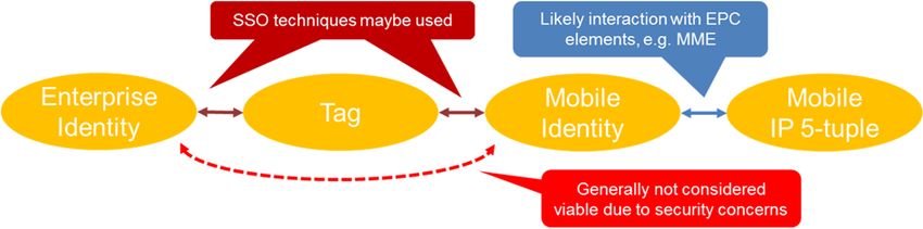
functionalities like radio coordination) and higher levels of security. On top of that, CRAN also facilitates
     the introduction of Artificial Intelligence (AI) in RAN to truly turn it into a “smart” RAN.
     The business models of MNOs have already changed fundamentally from offering bit pipes through their
     networks towards a data centric network driven by the services offered there. With regards to such a new
     data centric network, the network resources are efficiently utilized by virtual datacentres (vDCs). In
     contrast to past deployments, where an MNO had to deploy hard infrastructure everywhere from the city
     centre to the far end, in a modern service-driven network some of the traditional network sites and
     functions are becoming redundant. A RAN functionality can be flexibly deployed across multiple different
     locations over the same generic compute substrate. For example, a CRAN processing node can be
     deployed anywhere from what used to be the Central Office (CO) of a Public Switched Telephone Network
     (PSTN) (now more like a datacentre) to an in-field aggregation site for several cell-sites, to a cell-tower co-
     located hut. And because a CRAN deployment requires a substantial amount of processing power, any
     such site automatically becomes a MEC site – easily scalable to support other workloads.
     To summarize, CRAN and MEC are highly complementary technologies. When considered together, they
     make the near term economics of deploying CRAN hubs based on generic processing components much
     more attractive, while positioning an MNO to support (and generate revenue from) some of the key 5G
     applications that it would not be able to support otherwise.

Cloud RAN and MEC: A Perfect Pairing                                                                             6
Co-location: Deployment Scenarios and Architecture
     As noted above, CRAN and MEC are perfectly paired to accommodate emerging services, especially those
     requiring low latency or high bandwidth. Moreover, an attractive aspect of a cloud-based approach is that
     it enables a scalable solution, in particular making the capacity of the CRAN dynamic. How close a
     CRAN/MEC site is located to cell-sites will often determine how well it can support certain applications –
     or whether it can support them at all. As with most other things, it is a trade-off between cost and
     performance – locating a CRAN/MEC site in a CO is often less expensive than doing so in the field, but the
     cost is higher latency. Therefore, a careful understanding of the use-cases – i.e. which applications are
     likely to run at such a site – is critical. Table 1 presents a summary of such a use case analysis from [2].
                                        Table 1: Exemplary use case analysis
      Service            Content     Characteristic                        Cloud-Edge       Possible
                         Sever       Latency Bandwidth        Privacy      Coordination     Location
      AR/VR              Local       20Mbps       No           Processed        Access ring
      Surveillance                                                         data real-       (Edge DC)
                                                                           time Sync
      Smart factory      Local
The following scenario illustrates the usage of such an infrastructure. Suppose an MNO wants to run the
following applications at the edge:
An MNO’s own applications, which are Virtualized Network Functions (VNFs) that run on, e.g.,
OpenStack
Third-party Cloud Applications using a cloud-native based stack such as Microsoft’s Azure Stack
A CRAN implementation, which runs on bare-metal
Cloud-native containerized applications (using, e.g., Docker, AWS Greengrass, Microsoft Azure IoT
Stack)
Since both OpenStack and AzureStack are complete stacks, co-located deployment of these features
requires support for at least two independent OAM stacks. Moreover, at least one of these stacks must
support the “Containerized Domain” (or else a third OAM stack may be needed). Finally, bare metal
resources need to be managed by one of these OAM stacks (e.g. using OpenStack’s Ironic), or else also be
considered a separate (fourth!) “OAM stack”.
To summarize, co-location of MEC and CRAN – while technologically and economically attractive –
presents several challenges which much be addressed so that the value of the co-location can be fully
realized. The next sections delve deeper into this subject.
Cloud RAN and MEC: A Perfect Pairing 8Challenges in co-location
Repurposing existing CRAN deployments as MEC deployments is a frequent subject of on-going
discussions. Ideally, this should result in cost as well as rack space and power savings. But is this really the
case? Or does it make sense to deploy MEC next to, or near, CRAN instead? The answer depends on the
actual use case and deployment scenario.
For deployment, we need to think about brownfield vs greenfield. In a brownfield deployment, existing
equipment is being partially replaced, or augmented, with new MEC capable equipment. On the other
side, in a greenfield deployment all-new equipment and virtual functionality is deployed.
The use case dependency is more complex. For instance, in a shopping mall, systems are probably going
to find themselves in a difficult-to-handle environment at the edge, rather than a well-controlled
datacentre-style site. Such a challenging environment drives the need for dense, high performance
compute outside of the datacentre and creates a need for diversity in MEC infrastructure. Datacentre like
MEC deployments can easily use standard computing equipment; however, such infrastructure is not
optimized for the environment we described above. Such environments require Commercial-of-the-Shelf
(COTS) designs that have the capability to meet strict space constraints as well as to operate in dusty, less-
well maintained, less temperature-regulated conditions. What follows is an analysis of important
considerations to take into account when thinking about co-locating CRAN and MEC.
Management
The MEC system consists of functional as well as management and orchestration (MEC-MANO) entities,
which enable applications to run as virtual machines in a virtualized computing environment, following
the Infrastructure-as-a-Service (IaaS) model. Through the MEC management interfaces [3], [4], the MEC
system supports operations such as on-boarding applications, creating instances and orchestrating
services. In an incremental brownfield deployment approach, the MEC system would likely appear as a
standalone managed object sitting next to the existing CRAN implementation. Jointly managing the two
would require some kind of a posteriori intervention aimed at harmonizing the MEC-MANO part with the
CRAN. Such activity can be extremely challenging if the CRAN part requires its own components for
infrastructure management, e.g., when the CRAN sits on bare metal, which shares little with the MEC
components for virtualized infrastructure management.
Network Function Virtualization (NFV) is a powerful emerging technique in the telecom industry used to
decouple the network functions from dedicated physical network hardware and allow the network
services to be operated in a virtualized environment. Therefore, NFV is deemed to facilitate CRAN
deployments; in fact, CRAN contains non-real time functions (such as RRC, PDCP, etc.) and real time
functions: whereas the latter would be still implemented as physical network functions (PNF) the non-real
time functions could be virtualized as per the NFV paradigm.
ETSI ISG NFV is the leading Standard Developing Organization (SDO) in the NFV space, with the NFV
management and orchestration (NFV-MANO) system being one of the achievements most relevant to the
market. Like NFV, which provides the virtualized infrastructure to run network functions, MEC also uses a
virtualization platform to run the applications. Therefore there is the possibility for MEC and NFV to share
the same MANO and NFV Infrastructure (NFVI) systems to manage, orchestrate and execute the
applications and services. ETSI ISG MEC has issued a study [5] on MEC operating in an NFV environment to
allow MEC to re-use NFVI as virtualized infrastructure in either standalone or shared with NFV. Assuming
Cloud RAN and MEC: A Perfect Pairing 9both MEC and CRAN are built on the top of same NFVI, an approach under investigation of ISG MEC is to
have MEC MANO to communicate with NFV MANO to invoke the services by NFVI at IaaS layer. Therefore
MEC would be able to use the MANO and VNFs of CRAN to orchestrate its applications and services. But
the challenge of this approach is to maintain two MANO systems to manage the applications.
The MEC system not only interfaces to CRAN, but also interacts with applications. In Internet services,
many applications are running in clouds, such as Amazon Web Service (AWS) Greengrass, Microsoft Azure
and Google Cloud. Those clouds may use different virtualization stacks then CRAN. Therefore, it would be
a challenge for MEC to support porting such applications from the cloud and managing them running on
NFV based MEC without any modification.
A potential approach under investigation in ISG MEC is support of container-based virtualized
environment for MEC applications. For example, the orchestration engine of container-based
virtualization would be treated as a resource of IaaS and the Operating System (OS) image for containers
could be run as a virtual machine. Therefore the container-based virtualized environment would be able
to run as an independent Platform-as-a-Service (PaaS). As it is operated on different virtualization
infrastructure from the NFV, the MEC MANO may not be the same as NVF MANO, which would be helpful
to separate two different virtualization environments. But the challenge to this approach remains in the
management systems, i.e. the CRAN operator needs to maintain two separate MANO systems.
There are several factors limiting the codeployment of existing RAN or CRAN systems. One of them is
service availability. To date, few CRAN system have been deployed with sufficient provisioning for both
radio access and service delivery capacity. As radio access is the current revenue driver, it is unlikely that
MNO service providers will be inclined to risk service disruption. Thus, delivery of services requires a
separate virtualized computing environment that has access to radio data, such as location and possibly
user-plane data, and billing systems tied to the service consumer or the advertiser.
In private environments, e.g., shopping malls, the most likely scenario is that initial deployments will have
equipment placed separately from the existing (working) RAN, following the IT motto “never change a
running system”. Additionally, this enables a seamless cutover to add the new functionality, whereas a
replacement may result in a day-long period without local connectivity, which is undesirable. Integration
of CRAN into the fully managed virtual environment would still happen, but at a later time.
The benefits of augmenting existing systems are many, but the primary driver is revenue generation. The
ability to provide location-aware services sets the stage for an entirely new revenue stream based on local
advertisers addressing local shoppers. Provided security concerns are addressed the compute platform
needs only connection to appropriate data from the radio system to be application ready.
In contrast, in a greenfield scenario, one can take advantage to jointly deploy equipment for both radio
and MEC services, implementing the appropriate optimizations and/or customizations. In the shopping-
mall or stadium environment, where most early deployments are expected, opportunities for applications
and promotion within applications based on location arise (such as: “come buy dinner get free dessert”).
The key role of a MEC platform is to provide the necessary baseline support for applications, including the
ability to route traffic to and from them, pointers to the appropriate Domain-Name-System (DNS) records
and persistent storage. In addition, through the service registry the platform can keep track of and
advertise the services available in that MEC host, so that consumer applications (or the platform itself)
can discover services, and producer applications can make their services visible.
Cloud RAN and MEC: A Perfect Pairing 10The scope of the MEC platform is, generally speaking, the MEC host, which is defined as the entity
managed by MEC MANO stack. This implicitly restricts the host to a single IaaS domain under the control
of a single VIM instance. Nevertheless, with the appropriate level of abstraction and interfaces, complex
MEC deployments may span across multiple IaaS domains. As an example, one may think of an application
in a containerized environment like AWS Greengrass which consumes the Radio Network Information
(RNI) Service from an application running in the conventional MEC environment.
This abstraction and interfacing layer turns out to be necessary in order to grant inter-domain
communication, where different coupling levels can be envisioned:
Loose coupling refers to the ability of the MEC platform to make the service registry usable by non-
MEC applications, i.e., those applications managed through a MANO stack different from MEC. In
other words, loose coupling exposes MEC service APIs to applications sitting in other clouds.
Tight coupling requires additional logic to propagate MEC-defined management instructions to
other cloud domains, in order to concentrate management decisions at a single entity, e.g., to use
the capabilities of the MEC platform manager in order to program the data plane from another
cloud domain.
As already mentioned, MEC is already tackling the tight coupling problem between MEC and NFV
domains. This should cater for exposing MEC platform services to the CRAN when the latter is deployed as
a VNF, as per the ETSI-defined NFV system, including an optimized integration of the CRAN and MEC data
planes.
Security
MEC allows the provision of new types of services, which also introduces potential security threats and
vulnerabilities.
A likely model for MEC in a CRAN architecture is that MEC applications will run on the same physical
platforms as some network functions. These applications may be third party applications, not controlled
by the MNO directly. There are risks that these applications may exhaust resources needed by the
network functions. There are also risks that some poorly designed applications could offer hackers an
attack vector to infiltrate the platform and, hence, affect the network functions running on the platform –
or even risks that malicious applications do the same thing themselves.
In particular, some MEC applications are intended to influence the mobile network configuration
(including both RAN and Core Network (CN) parameters) in real time in order to improve network
efficiency and customer experience. If this influence is too large, it could cause severe degradation, or
denial of service to other users. Some applications might starve competitor applications (and their
customers) of radio resources, either accidentally or maliciously.
It is, thus, paramount for service providers to be sure that a system malfunctioning in the MEC
environment does not impact the CRAN part. Whether this malfunctioning comes from application
malicious behaviour or a system crash is up to the service provider to troubleshoot and fix. In all cases,
protection and isolation mechanisms should be in place in order to ensure that the CRAN components are
still in service and able to deliver the mobile coverage to end users.
Meanwhile, where MNOs host third party applications in a MEC system, there is an opportunity for MNOs
to provide security / assurance services for those applications. The example services include performing
integrity assurance checks on applications at installation or upgrade, or after a server restart, and
Cloud RAN and MEC: A Perfect Pairing 11exposing security services APIs to sufficiently trusted third party MEC applications, e.g. for user
identification.
Networking
In order to benefit from all expected MEC advantages (e.g. low latency, backhaul traffic reduction and local
breakout), the closest point to UEs for MEC deployments is close to the eNBs, which may be distributed or
centralized. That location presents challenges related to mobility event handling (item being addressed by
ETSI MEC) and guaranteeing execution of operations required on the mobile traffic that, with MEC close to
eNB, may not reach the SGi interface.
CRAN, via the centralization it provides, has the potential to reduce the number of MEC hosts required to
provide a service to the same population. However, different CRAN deployment strategies may be followed.
The splitting point of functions between the distributed Remote Radio Heads (RRHs) and the centralized
BBUs is just one aspect. For 4G, CPRI is commonly adopted, with RRH units only executing RF functions. For
5G this may be different due to the higher demanded bandwidths and the recently specified eCPRI [15] that
will contribute to the solution. While this aspect shall not influence MEC, the type of BBU centralization
(hostelling vs. pooling) determines the number of mobility events to be handled by MEC and, thus, overall
system efficiency and the user experience.
By concentrating BBUs (hostelling) or reducing the BBU number (pooling), actions to be taken related to
user mobility are local or even inexistent whenever the UE moves inside the geographical area covered by
the centralized BBUs. Thus, the geographical area a UE can move without changing servicing MEC host gets
bigger.
Running MEC close to CRAN in a scenario where the CRAN is virtualized, creates the conditions for MEC to
share the same virtualization infrastructure. In such scenario the interfaces to be handled are established
inside that infrastructure, provided the required handling and forwarding are available. In a scenario where
the BBU may be implemented as a chain of modular functions, MEC may be inserted in that chain prior to
S1 encoding.
Many of these challenges will also exist with 5G, which also uses GTP, and with other access technologies,
whenever users’ traffic crosses the edge encapsulated, with the sessions anchor point, QoS enforcement,
IP addresses assignment, Lawful Interception (LI) and usage accounting being done deeper in the
network, e.g. at a Broadband Network Gateway. The difference for 5G is that, being a technology
currently under specification, it already accounts for edge computing, with 5G architecture entities (e.g.
the User Plane Function) close to the UE, supporting those functions and allowing traffic to be steered by
the Application Functions (AFs). Other features are being added, like a ‘Common API Framework’, to
complement that.
Regulatory
MNOs are required to provide Law Enforcement Agency (LEA) support including Lawful Interception (LI)
and Retained Data (RD) capabilities for traffic carried on their networks. Typically this functionality is
supported by core network elements for all data passing through these elements.
When implementing MEC, some traffic may be generated or manipulated inside the MEC system or may
come from a local breakout connection, thus not passing through the core network and not supported by
the existing LI solution in the network.
Cloud RAN and MEC: A Perfect Pairing 12Moreover, in the context of MEC, placing multiple additional LI points around the network edge raises
security risks:
there will be many more LI points than in traditional deployments
edge nodes are likely to be more exposed to attack than core nodes.
It is therefore recommended that LI and RD collection functions are implemented at the edge of the
network, alongside or as part of the functionality being intercepted. Any edge node including LI / RD
collection features must support strong physical security requirements similar to core network sites.
Further work would be required to examine specifically how and where the LI/RD functionality should be
included in a network architecture.
Cloud RAN and MEC: A Perfect Pairing 13Enabling and Exposing RAN Services in MEC
Two key issues of CRAN deployment with MEC are a) the ability of the CRAN to exploit the MEC service
APIs within the CRAN, and b) the exposure of CRAN information to MEC applications. In the remainder of
this section, we will focus on the role and possible benefits of exploiting the following MEC service APIs
within a CRAN towards service optimization (e.g., measured by means of the Quality-of-Experience –
QoE):
Radio Network Information (RNI) API [6];
Location API [7];
UE Identity API [8];
Bandwidth Management API [9].
The reference provided for each API refers to the respective ETSI MEC Group Specification (GS). To
complement the specifications, ETSI ISG MEC also provides a supplementary description file compliant to
the OpenAPI specification [10]for each of these APIs. OpenAPI is a specification for machine-readable
interface files for describing, producing, consuming and visualizing RESTful web services. The description
files are hosted on the ETSI Forge site: https://forge.etsi.org/.
RNI API
The Radio Network Information Service (RNIS) is a service that provides radio network related information
to MEC applications and to MEC platforms. Typical information provided by RNIS includes radio
conditions, user plane related measurements, radio access bearer information and corresponding change
notifications.
In further detail, radio network information can be broadly classified into the following groups.
Radio Access Bearer (RAB) information, which contains data about existing E-RABs associated with
a specific MEC application instance. In addition to existing E-RABs, RNIS also provides information
on RAB establishment, RAB modification and RAB release.
Public Land Mobile Network (PLMN) information, which contains data about the underlying
mobile network that the MEC application is associated to.
S1 Bearer information, which represents data about the S1-U bearer. In addition to existing S1
bearers, the RNI service also provides information on S1 bearer establishment, modification and
release.
Cell change information, which includes the following information elements: handover status,
PLMN information and E-UTRAN cell global identifier
UE RRC measurement reports
UE timing advance, which is necessary to ensure that uplink and downlink sub frames are
synchronized at the eNB.
The RNI service exposes the radio network information to the RNI service consumers using a RESTful API.
The standard RESTful methods, i.e., GET, PUT, POST and DELETE, can be utilised for RNI requests and
responses, which support individual requests for information as well as subscription to notifications.
Cloud RAN and MEC: A Perfect Pairing 14RESTful RNI Request
RESTful RNI Response
RNI Service RNI Service
Consumer
Figure 2: RESTful RNI API
A MEC application instance which is running at a MEC host can leverage the RNIS to optimize
performance or to provide new types of services based on up-to-date radio network information. A
typical example is Virtual Reality/ Augmented Reality (VR/AR) applications that can adjust TCP congestion
windows and video formats that are adaptive to the air interface throughput. The key point of
optimization of those services is the accuracy of radio network information which leads to a real-time
interaction requirement between CRAN and MEC.
5G CRAN supports centralizing the upper layers of the radio stacks at a Central Unit (CU), while
distributing the lower layers into Distributed Units (DUs). Different protocol stack functional splits with
ideal/non-ideal fronthaul are also supported between the CU and the DUs. This flexible architecture of 5G
CRAN ensures that the radio information from not only long-term Radio Resource Management (RRM)
but also short term RRM could be pulled out from the CU directly. With the enhanced real-time 5G RAN
L3/L2/ L1 status information (e.g., beam info, Sounding Reference Signal (SRS) measurements), RNIS will
be widely used in many scenarios, such as indoor positioning navigation in shopping malls, rapid RAT
selection in V2X, etc.
Since MEC is deployed much closer to the RAN, the best way for RNIS to get radio information is direct
interaction with CRAN rather than taking a long route through a network function of the core network
(e.g., Network Exposure Function). Especially when co-located with CRAN, MEC may share the same NFVI
with CRAN. The interaction between MEC and CRAN could be performed via internal interfaces, which
could improve communication efficiency and support real time applications effectively by leveraging the
performance advantage of the shared infrastructure.
Figure 3 shows how the RNIS could obtain radio information from co-located CRAN with a shared NFVI. F1
is an interface between the CU and the DU defined by 3GPP. Mp1 is a reference point defined by ETSI
MEC for exposing the RNIS to authorized applications. The interaction between CRAN and MEC calls for
further investigation.
Cloud RAN and MEC: A Perfect Pairing 15Figure 3: MEC obtains RAN information directly from CRAN
Location API
The Location Service is a service that provides location related information to MEC platforms and MEC
applications, e.g., AP/eNodeB location, UE location, UEs in a specific area, or notifications of UE(s)
entering an area. It leverages the Zonal Presence service described by the Small Cell Forum [11], [12] and
is accessible through the API defined in the Open Mobile Alliance (OMA) specification “RESTful Network
API for Zonal Presence” [13]. In the context of MEC, the Anonymous Customer Reference [14] may
address particular user categories via the API and may also discover how the 3GPP Cell Identifiers can be
mapped to the Access Point identifier of the OMA API.
With respect to a MEC deployment at the edge of the CRAN domain, what is of interest are the potential
sources of UE location of which there are two: firstly, from the UE itself, e.g., a Global Navigation Satellite
System (GNSS) fix, which may benefit from network originated assistance information such as A-GPS data;
and secondly network based location with low or high precision. An example of low precision would be
serving cell alone, or, higher precision could be provided using techniques such as network based
trilateration and triangulation, which may be augmented with UE originated information such as time
difference measurements as requested by the network.
The UE may provide GNSS-like fixes via higher layer protocols, for instance at the application layer and
particularly in an Over the Top (OTT) context, but that would not be directly available to the RAN. It may
also be specifically requested to provide it via Radio Resource Control (RRC) signalling through features
such as Radio Link Failure (RLF) and Minimization of Drive Tests (MDT), in which case such information
would be available in the RAN and, therefore, could be exposed by the RAN and used as a source of
information for the Location API. With respect to low precision information, such as the serving cell, the
RAN is also well placed to make that information available to the MEC domain, where it is worth noting
only the serving eNodeB is generally exposed to the Evolved Packet Core (EPC). In the absence of a GNSS
fix from the UE, the network may offer higher precision location estimates through the location services
architecture, but then the key network elements are typically located outside of the RAN. Therefore, an
Cloud RAN and MEC: A Perfect Pairing 16alternative may be for the MEC platform or MEC application to generate the information necessary for
the Location API itself based on the raw information available to it, e.g., that obtained from RNIS.
Focusing on security and anonymity challenges , the Location API responds to a number of issues that
need to be resolved in the MEC environment. Such privacy and security-related issues are expected to be
prominent when MEC hosts are deployed across the CRAN.
Question 1: Is this safe? Can a wrongdoer hack this?
Location data is privacy sensitive. Knowing where people are, on the other hand, is important for a
business, e.g., if a merchant knows someone is currently in front of his/ her store (or a competitor’s
store), this is of extra business value. In order for this information availability to be accepted in the wide
public, there need to be mechanisms within the CRAN to keep this information safe.
Question 2: Can it be done anonymously?
This can be a clear, acceptable answer to the public’s concerns – keep the location data anonymized, or
the location expressed in a way that ensures a user can select to remain anonymous.
In order to address these challenges, data should be shared between applications using a generic,
controlled API to avoid extraction and unintended leakage of private information. This also responds to
further privacy concerns by avoiding a growing database of personal information in multiple locations.
Also importantly, a multi-tenant security model, potentially even by separating processes not only
through virtualization but even running in separate physical domains, enables extended privacy
protection by avoiding extraction of data from processes sharing the same physical domain. Such security-
driven multi-tenancy needs to be investigated when it comes to a CRAN deployment.
UE Identity API
The UE Identity feature is provided to allow authorized MEC application instances to invoke UE specific
traffic rules within the MEC platform. Each UE is identified by a unique “tag” which is provided to the
application. The tag acts as an intermediary identifier between a UE’s mobile IP 5-tuple (where the mobile
identity may be used as a further intermediary identifier, i.e., the International Mobile Subscriber Identity
/ IMSI) and its external identifier, e.g., its enterprise identity (Figure 4). In this manner, masking is
achieved between the MNO’s identification system and that of any external network. The MEC platform is
provided with the UE to tag mapping information, but how that mapping is realized is currently outside
the scope of the MEC specifications. In order to trigger the UE traffic rules, the MEC application instance
registers the relevant tag with the MEC platform via the UE Identity API. Following successful registration,
the MEC platform then activates the corresponding traffic rule(s) linked to the tag. Later, if the application
instance no longer wishes to use the traffic rule for that user, it may de-register the tag by invoking the
de-registration procedure.
Cloud RAN and MEC: A Perfect Pairing 17Figure 4 Identity mapping using the Tag
A significant factor with respect to a CRAN approach is that the mobile identity (IMSI) would not
inherently be available in the CRAN domain. This is certainly the case for LTE if it is assumed that the
northbound interface from the CRAN is S1, or the N2/N3 interface with regards to 5G NG-RAN. The IMSI is
generally only exposed within the LTE EPC and communicated infrequently by the UE. The implication is
that a secondary means is required to provide the information necessary to link the traffic flows
supported within the CRAN with specific UE identities. The CRAN would only be aware of temporary
identifiers such as the System Architecture Evolution Temporary Mobile Subscriber Identity (S-TMSI),
associated Radio & S1 Bearer IDs and S1-Application Protocol (AP) UE IDs. Therefore, the MEC Platform
would need to be provided with the information to link a specific tag with the appropriate temporary
identifiers. A solution would be to deploy probe based agents in the EPC. Specifically, the role of the agent
would be to extract IMSI/IMEI identifiers with their associated temporary identities for each connection
session by probing key interfaces within the EPC. The agent would then provide this IMSI based Customer
Experience Management (CEM) data feed with the necessary paring information to the MEC platform.
Using this information, the MEC platform could then fulfil the UE specific traffic rules as required.
With such a solution in place, a clear advantage with a CRAN type approach is the centralization it affords.
This allows traffic rules to be applied at the edge of the RAN across a wide area and for many UEs, rather
than at an intermediate point along the S1 interface that would require S1 de-encapsulation and re-
encapsulation.
Bandwidth Management API
The Bandwidth Management service (BWMS) API is another means of supporting the use cases and
requirements relevant to MEC technology. The mission of this service API lies in the effective and timely
satisfaction of bandwidth requirements tailored towards a single MEC application instance, or multiple
sessions of the same application. Such bandwidth requirements may refer to the bandwidth required to
support the instantiated application (or session), to the bandwidth priority of the application, or to both.
Given that different MEC applications concurrently instantiated at a MEC host may have different
bandwidth requirements, or the same bandwidth requirement may characterize MEC applications
tailored to UEs located at different distances from the edge of the RAN, the BWMS API can aggregate all
requests and share the available resources in an optimal and fair manner.
In a non-CRAN deployment involving MEC hosts located at the edge, an advantage of enabling and
exposing the BWMS API consists in making “local” decisions on bandwidth allocation, which enhance
performance and are reached in a timely manner due to proximity. However, with the lack of any
centralized coordination provided by a central entity of the equivalent CRAN, only intra-cell UEs are
expected to benefit from decisions upon bandwidth allocation. This means that, for example, out-of-cell
interference might affect the performance of some of the MEC applications.
Cloud RAN and MEC: A Perfect Pairing 18On the other hand, consider a CRAN deployment without any MEC hosts existing at the edge (and,
consequently, the non-availability of the BWMS API). Centralized bandwidth allocation is expected to
have a positive impact on performance due to coordination, albeit largely depending on the
characteristics of the fronthaul connection. In other words, this means that the quality of the fronthaul
interface may negatively influence the decisions upon bandwidth management.
Motivated by the above arguments, one would expect that a joint CRAN/ MEC deployment, together with
the enablement of the BWMS API, will address the coordination efficiency / timeliness trade-off, by
properly exposing network-wise bandwidth information to the MEC host. Such information could be
considered by the BWMS API with the aim of boosting the performance of the MEC application instances.
Conclusion
In this paper, we present a case that MEC and CRAN are highly complementary technologies. Each makes
the economics of deploying the other significantly more attractive. However, such co-location requires
solving a number of technical challenges as well as figuring out how to maximize the revenue generating
potential of co-location.
This paper is meant as an introductory guide to the industry as it works on resolving these challenges.
We highlight the importance of understanding the deployment scenarios and use-cases and the
architectural trade-offs that these may impose. We then provide a summary of key technical challenges
and high-level overview of solution approaches. The last part of the paper provides an overview of how
ETSI MEC services, such as Radio Network Information Service, can be used as revenue generating tools in
a CRAN-MEC environment.
This paper is but a brief, and, thus a high-level overview. Our hope, however, is that it is a useful starting
point on the journey towards effective and highly profitable joint CRAN/MEC deployments.
Cloud RAN and MEC: A Perfect Pairing 19Abbreviations
AI Artificial Intelligence
AF Application Function
API Application Programmers Interface
AR Augmented Reality
AWS Amazon Web Services
BBU Baseband Unit
BWMS Bandwidth Management Service
CAPEX Capital Expenditure
CN Core Network
CO Central Office
COTS Commercial-of-the-Shelf
CRAN Cloud RAN
CU Central Unit
DC Data Centre
DNS Domain Name System
DU Distributed Unit
eMBB enhanced Mobile Broadband
EPC Evolved Packet Core
GNSS Global Navigation Satellite System
GPP General Purpose Processor
GS Group Specification
IaaS Infrastructure-as-a-Service
IMSI International Mobile Subscriber Identity
ISG Industry Specification Group
LEA Law Enforcement Agency
LI Lawful Intercept
MANO Management and Orchestration
MEC Multi-access Edge Computing
mMTC massive Machine Type Communication
MNO Mobile Network Operator
NFV Network Function Virtualization
NFVI NFV Infrastructure
OAM Operation and Management
OPEX Operational Expenditure
OS Operating System
OTT Over-the-Top
PaaS Platform-as-a-Service
PLMN Public Land Mobile Network
PSTN Public Switched Telephone Network
Cloud RAN and MEC: A Perfect Pairing 20PoP Point-of-Presence
QoE Quality of Experience
QoS Quality of Service
RAB Radio Access Bearer
RAN Radio Access Network
RD Retained Data
RNI Radio Network Information
RNIS RNI Service
RRC Radio Resource Control
RRH Remote Radio Head
SDO Standard Developing Organization
SRS Sounding Reference Signal
TCO Total Cost of Ownership
URLLC Ultra Reliability and Low Latency Communication
V2X Vehicular-to-Everything (as in car-based communication)
vDC virtual DC
VNF Virtualized Network Function
VR Virtual Reality
Cloud RAN and MEC: A Perfect Pairing 21References
[1] ITU-R Recommendation M.2083-0, “IMT Vision – Framework and overall objectives of the future
development of IMT for 2020 and beyond”, Sep. 2015.
https://www.itu.int/dms_pubrec/itu-r/rec/m/R-REC-M.2083-0-201509-I!!PDF-E.pdf
[2] Huawei White Paper, “5G Unlocks A World of Opportunities – Top Ten 5G Use cases,” Huawei, Nov
2017. http://www.huawei.com/us/industry-insights/mbb-2020/trends-insights/5g-unlocks-a-world-
of-opportunities
[3] ETSI GS MEC 010-1, “Mobile Edge Computing (MEC); Mobile Edge Management; Part 1: System, host
and platform management” (2017-10).
http://www.etsi.org/deliver/etsi_gs/MEC/001_099/01001/01.01.01_60/gs_MEC01001v010101p.pdf
[4] ETSI GS MEC 010-2, “Mobile Edge Computing (MEC); Mobile Edge Management; Part 2: Application
lifecycle, rules and requirements management” (2017-07).
http://www.etsi.org/deliver/etsi_gs/MEC/001_099/01002/01.01.01_60/gs_MEC01002v010101p.pdf
[5] ETSI GR MEC 017 V1.1.1, “Mobile Edge Computing (MEC); Deployment of Mobile Edge Computing in
an NFV environment” (2018-02)
http://www.etsi.org/deliver/etsi_gr/MEC/001_099/017/01.01.01_60/gr_MEC017v010101p.pdf
[6] ETSI GS MEC 012 V1.1.1, “Mobile Edge Computing (MEC); Radio Network Information API” (2017-07)
http://www.etsi.org/deliver/etsi_gs/MEC/001_099/012/01.01.01_60/gs_MEC012v010101p.pdf
[7] ETSI GS MEC 013 V1.1.1, “Mobile Edge Computing (MEC); Location API” (2017-07)
http://www.etsi.org/deliver/etsi_gs/MEC/001_099/013/01.01.01_60/gs_MEC013v010101p.pdf
[8] ETSI GS MEC 014 V1.1.1, “Mobile Edge Computing (MEC); UE Identity API” (2018-02)
http://www.etsi.org/deliver/etsi_gs/MEC/001_099/014/01.01.01_60/gs_MEC014v010101p.pdf
[9] ETSI GS MEC 015 V1.1.1, “Mobile Edge Computing (MEC); Bandwidth Management API” (2017-10)
http://www.etsi.org/deliver/etsi_gs/MEC/001_099/015/01.01.01_60/gs_MEC015v010101p.pdf
[10] OpenAPI Specification https://github.com/OAI/OpenAPI-SpecificationOAS
[11] SCF 084.07.01: “Small cell zone services - RESTful bindings”
https://scf.io/en/documents/084_-_Small_Cell_Zone_services_RESTful_Bindings.php
[12] SCF 152.07.01: “Small cell services API”
http://scf.io/en/documents/152_-_Small_cell_services_API.php
[13] RESTful Network API for Zonal Presence V1.0 (2016)
http://www.openmobilealliance.org/release/REST_NetAPI_ZonalPresence/V1_0-20160308-C/OMA-
TS-REST_NetAPI_ZonalPresence-V1_0-20160308-C.pdf
[14] RESTful Network API for Anonymous Customer Reference Management V1.0 (2013)
http://www.openmobilealliance.org/release/REST_NetAPI_ACR/V1_0-20131224-A/OMA-TS-
REST_NetAPI_ACR-V1_0-20131224-A.pdf
Cloud RAN and MEC: A Perfect Pairing 22[15] eCPRI Transport Network V1.0, “Common Public Radio Interface: Requirements for the eCPRI
Transport Network,” Oct. 2017.
http://www.cpri.info/downloads/Requirements_for_the_eCPRI_Transport_Network_V1_0_2017_10_
24.pdf
Cloud RAN and MEC: A Perfect Pairing 23ETSI 06921 Sophia Antipolis CEDEX, France Tel +33 4 92 94 42 00 info@etsi.org www.etsi.org This White Paper is issued for information only. It does not constitute an official or agreed position of ETSI, nor of its Members. The views expressed are entirely those of the author(s). ETSI declines all responsibility for any errors and any loss or damage resulting from use of the contents of this White Paper. ETSI also declines responsibility for any infringement of any third party's Intellectual Property Rights (IPR), but will be pleased to acknowledge any IPR and correct any infringement of which it is advised. Copyright Notification Copying or reproduction in whole is permitted if the copy is complete and unchanged (including this copyright statement). © ETSI 2018. All rights reserved. DECT™, PLUGTESTS™, UMTS™, TIPHON™, IMS™, INTEROPOLIS™, FORAPOLIS™, and the TIPHON and ETSI logos are Trade Marks of ETSI registered for the benefit of its Members. 3GPP™ and LTE™ are Trade Marks of ETSI registered for the benefit of its Members and of the 3GPP Organizational Partners. GSM™, the Global System for Mobile communication, is a registered Trade Mark of the GSM Association.
You can also read