CNG DI Combustion Processes in Combination with High-load EGR and the Miller Process
←
→
Page content transcription
If your browser does not render page correctly, please read the page content below
RESE ARCH G as Engines
AUTHORS
CNG DI Combustion Processes in Combination
with High-load EGR and the Miller Process
Compressed Natural Gas (CNG) represents a short- and medium term addition to
Johannes Oder, M. Sc.
is Research Associate at the fuel portfolio for turbo-DI spark ignition engines, as it is readily available world-
the Institute for Mobile
Systems (IMS) of wide and can contribute significantly to greenhouse gas reduction due to the low
OVGU Magdeburg
University (Germany).
C/H ratio. As part of the FVV research project No. M2414, a homogeneous stoichio
metric combustion process with direct natural gas injection in combination with
high-load exhaust gas recirculation was investigated at RWTH Aachen University
and Otto von Guericke University Magdeburg.
Christian Wouters, M. Sc.
is Research Associate
at the Institute for
Combustion Engines
(VKA) at RWTH Aachen
University (Germany).
Prof. Dr.-Ing.
Hermann Rottengruber
is Head of the Institute for
Mobile Systems (IMS) of
OVGU Magdeburg
University (Germany).
Prof. Dr.-Ing.
Stefan Pischinger
is Head of the Institute for
Combustion Engines (VKA)
at RWTH Aachen
University (Germany).
© VKA
84 www.springerprofessional.com/automotive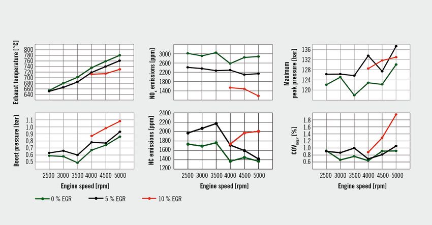
1 INTRODUCTION 2 METHODOLOGY
2 ME THOD OLO GY
3 INJECTOR P OSITION The optical results are indispensable for the validation of the CNG
4 SINGLE- CYLINDER INVESTIG ATIONS injector model with a 3-D simulation by Computational Fluid
5 MULTI- CYLINDER INVESTIG ATIONS Dynamics (CFD). Based on the simulations, the combustion cham-
6 THERMODYNAMIC INVESTIG ATIONS ber and piston geometry, the DI injector spray angle and the
7 TR ANSFER ABILIT Y OF THE DATA adjustable parameters for the injection can be optimized.
8 LONGITUDINAL SIMUL ATION For the thermodynamic analysis of the combustion process, a
9 SUMMARY AND OUTLO OK direct injection, Spark Ignition (SI) single-cylinder research engine
with a Compression Ratio (CR) = 13, a displacement of 0.4 l, four
valves and variable valve timing was used. The focus of the inves-
tigation was on the evaluation of the advantages and disadvantages
of the individual injection configurations: central or lateral instal-
lation position of the CNG DI injector in the cylinder head. An
optimal operating strategy for a natural gas engine with direct
injection was determined on this basis. For the bench tests, a Ford
engine (EcoBoost, 1.0 l, 103 kW rated power) was converted from
gasoline to CNG operation. The CNG DI injectors are solenoid
1 INTRODUCTION injectors with outward-opening nozzles that are suitable for injec-
tion pressures between 6 and 16 bar. Taking into account the fun-
The focus of the research project was on the overall evaluation of damentals of gas dynamics, there must be a supercritical pressure
the homogeneous stoichiometric combustion process in combina- ratio for a linear relationship between the time of injector activa-
tion with high-load Exhaust Gas Recirculation (EGR) and Miller tion and the amount of injected fuel [1].
valve control. The project was carried out at the Institute for Com-
bustion Engines (VKA) at RWTH Aachen University and the Insti-
3 INJECTOR POSITION
tute for Mobile Systems (IMS) at the Otto von Guericke University
(OVGU). Fundamental mixture formation investigations were carried 3-D CFD simulations were carried out to investigate the influence
out both in a low-pressure injection chamber and on a motored, of the time of injection and the injector position. Both the central
optically accessible single-cylinder research engine. In addition, and the lateral injector position were simulated at low-end torque
the investigations were numerically supported. The findings were with an early injection time of 320 °CA before TDC and a late injec-
transferred to a geometrically identical thermodynamic single-cyl- tion time of 160 °CA before TDC, FIGURE 1. At an early injection
inder research engine and supplemented by numerical investiga- time, the primary tumble generated by the inflowing air was signifi-
tions. The experiments were transferred to a Ford multi-cylinder cantly increased with lateral injection, whereas injection with a cen-
engine, the results of which were finally incorporated to a 0-D/1-D tral injector position hinders the formation of the primary tumble
engine model. The numerical and thermodynamic results of the because the gas jet is directed toward the tumble center. Even
investigation are presented in this article. during compression, the central injection does not reach the tumble
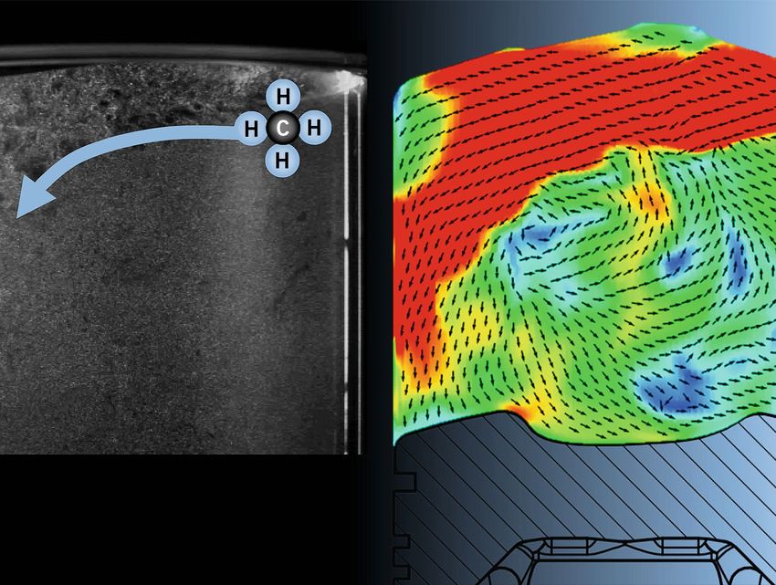
FIGURE 1 Influence of the injection timing and the injector
position at n = 1500 rpm and IMEP = 20 bar on tumble
formation in the combustion chamber (© VKA | IMS)
MTZ worldwide 05-06|2021 85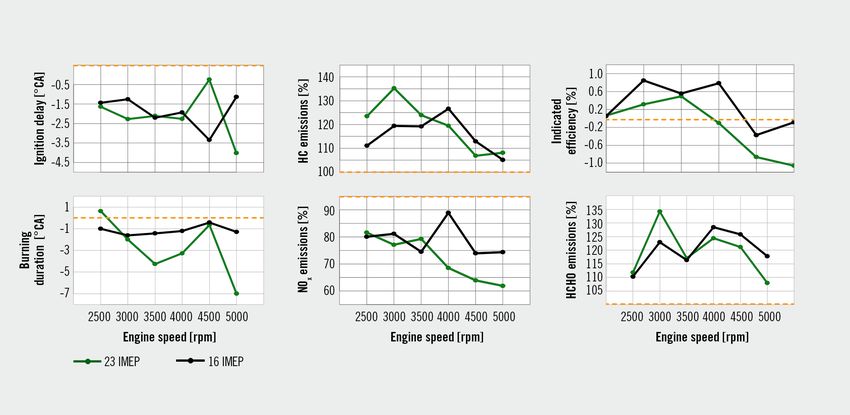
RESE ARCH G as Engines

FIGURE 2 EGR variation at n = 1500 rpm and IMEP = 20 bar with late central injection; Tint = 25 °C; pCNG = 16 bar; DI central; CR = 13; air-fuel ratio λ = 1;
Exhaust Valve Closed (EVC) = 9 °CA (before TDC); Intake Valve Open (IVO) = 15 °CA (after TDC); Start Of Injection (SOI) = 150 °CA (before TDC) (© VKA | IMS)

level of the charge motion without injection. It can be clearly seen             gas. However, the increased inert gas fraction resulted in an
in FIGURE 1 that at a late injection time, lateral injection also leads          increased burn duration by 5 °CA. At the same time, the combus-
to a significant increase in tumble, while injection with a central              tion stability (expressed by the Coefficient of Variation (COV) of
position hardly affects the in-cylinder charge motion in this case.              IMEP) COVIMEP increased by 1.2 percentage points. The most
                                                                                 important thermodynamic advantage of the high EGR rates can be
                                                                                 seen in lower heat losses during combustion. Due to the lower com-
4 SINGLE-CYLINDER INVESTIGATIONS
                                                                                 bustion temperatures, nitrogen oxide (NOX) emissions were reduced
The fundamental investigations of the combustion process included                by 75 %. The emissions trade-off remains, resulting in 100 %
stoichiometric part-load and full-load operation, charge dilution by             increased emissions of unburned Hydrocarbons (HC).
means of (low-pressure) EGR, and excess air as well as a catalytic con-
verter heating strategy. FIGURE 2 shows an example of EGR variation
                                                                                 5 MULTI-CYLINDER INVESTIGATIONS
at the operating point representing low-end torque at n = 1500 rpm
and an Indicated Mean Effective Pressure IMEP = 20 bar. The indi-                Other modifications were made to the multi-cylinder engine in addi-
cated efficiency was increased by 0.7 percentage points with an                  tion to major changes such as a CNG rail and CNG DI injectors.
EGR rate of XEGR = 28 %. Due to the high anti-knock properties of                The design of the high pressure EGR line was derived from a 1-D
CNG, the location of the center of combustion was already optimized              simulation calculation. The homogeneous distribution of the
for minimum fuel consumption with XEGR = 0 %. In this regard,                    exhaust gas was checked in a 3-D CFD simulation. Due to the high
increasing the EGR rate did not improve the efficiency of the high               anti-knock properties of natural gas, the CR was increased from
pressure process. Having the location of center of combustion opti-              10 : 1 to 13 : 1 using a modified piston geometry, corresponding to
mized for minimum fuel consumption did not reduce the cylinder                   that of the single-cylinder engine. The investigations of the various
peak pressure, despite the additional amount of recirculated exhaust             EGR rates were carried out with the series ignition system.

                               At 5 % EGR [%]                At 10 % EGR [%]

 NO x emissions                ⇩ 12–26                       ⇩ 40–60

 HC emissions                  ⇧ 12–26                       ⇧ 12–26

 CH 4 emissions                ⇧ 4–24                        ⇧ 26–47

 HCHO emissions                ⇧ 10–28                       ⇧ 40–60

 CO emissions                  No trend evident              No trend evident                 TABLE 1 Comparison of changes in raw emissions with
                                                                                              EGR variation and without EGR (© VKA | IMS)

86                                                                                                               www.springerprofessional.com/automotive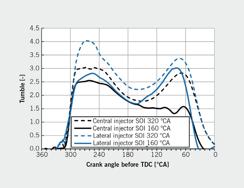
6 THERMODYNAMIC INVESTIGATIONS                                               with increased engine speed could also be realized, the maximum
                                                                             being reached at 10 %. The boost pressure had to be adjusted
In CNG operation, the mean cylinder pressure increased due to                because the recirculated exhaust gas displaces part of the charge
the higher compression ratio and advanced ignition. However, due             air. The total mass flow, exhaust gas back pressure and scaveng-
to the peak pressure limitation of 160 bar in the full-load investi-         ing losses increase accordingly. The location of the center of com-
gations, the optimal phasing of the center of combustion could not           bustion could be kept at approximately 8 °CA after TDC for all
be maintained.                                                               operating points. By adding cooled exhaust gas at a temperature
   The original idea of reducing the cylinder peak pressure at a             Tint = 25 °C it was possible to counteract an increase in the raw
constant center of combustion by using additional exhaust gas                NOX emissions, the combustion and the exhaust gas temperatures,
turned out to be impractical, since the influence of the additional          even with increasing boost pressure. Due to the higher heat capac-
exhaust gas mass in the combustion chamber dominates over the                ity, the inert gas fraction leads to lower combustion temperatures
reduced combustion temperature. However, this was contrasted                 and consequently to a longer combustion delay and slower com-
by a slight increase in the indicated efficiency up to n = 4500 rpm          bustion. The ignition timing was advanced in order to keep the
due to reduced wall heat losses and a significant reduction in NOX           same center of combustion. Nevertheless, the mean and maximum
emissions over the entire operating range. However, the HC emis-             cylinder peak pressures increased slightly due to the EGR.
sions increased noticeably between 12 and 26 %, TABLE 1. The same
trend was observed in the single-cylinder engine investigations.
                                                                             7 TRANSFERABILIT Y OF THE DATA
   There were no knocking events throughout all of the full-load
investigations at a mean pressure of IMEP = 23 bar. Since the                A trend line comparison was used to determine whether the results
peak pressure limitation made it difficult to estimate the potential         from the investigations of the high-load EGR at 70 % load can be
of the high-load EGR with regard to engines with higher limits, the          transferred to engines with higher peak pressure limits.
investigations were repeated at 70 % of full-load torque. At these              While FIGURE 3 shows the absolute changes, FIGURE 4 represents
operating points, the limitation of the cylinder pressure of 160 bar         changes due to the influence of 5 % EGR on the basis of the mea-
is not relevant. A trend line comparison illustrates that the results        surements without EGR. The efficiency gain increased with a con-
generated from this can be transferred. Based on the given com-              stant center of combustion and the negative effects shifted toward
parability to the tests at full load (IMEP = 23 bar), only the results       higher engine speeds. The combustion delay and duration increased
at 70 % load (IMEP = 16 bar) are shown in FIGURE 3. The various              to the same extent. The emission behavior correlated for full load
EGR rates could be realized from n = 2500 rpm only, due to the               and 70 % load. With the exception of the operating points from
minimum pressure gradient required between the exhaust and                   n = 4000 rpm, it can be established that the combustion tempera-
intake side to implement the high-pressure EGR. Higher EGR rates             ture can be reduced to a greater extent by high-load EGR at full load.

FIGURE 3 EGR variation at IMEP = 16 bar, n = 2500–5000 rpm; pCNG = 16 bar; SOI = 360–180 °CA (before TDC);
mean peak pressure = 102–110 bar; maximum peak pressure = 115–137 bar; λ = 1 (© VKA | IMS)

MTZ worldwide      05-06|2021                                                                                                                  87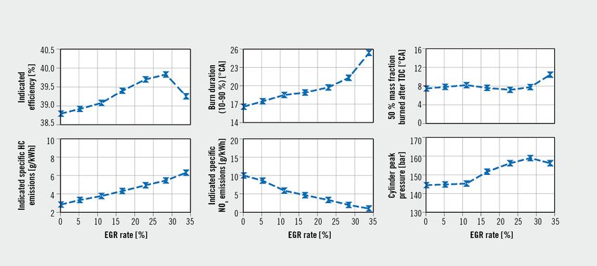
RESE ARCH G as Engines

FIGURE 4 Comparison EGR influence on IMEP = 16 bar and 23 bar; pCNG = 16 and 23 bar; SOI = 360–180 °CA (before TDC); λ = 1 (© VKA | IMS)

   The investigation of both operating ranges shows similar behav-             center of combustion due to a limited peak pressure. The multi-
ior with regard to emissions and combustion. The results can                   cylinder engine investigations with high-load EGR showed a high
therefore be regarded as consistent and allow a transfer to engines            NOx reduction potential with slight efficiency advantages up to
with higher peak pressure limits.                                              n = 4000 rpm. The peak pressures could not be reduced with the
                                                                               same center of combustion. The findings in this study show
                                                                               that the use of CNG as a fuel, together with corresponding engine
8 LONGITUDINAL SIMULATION
                                                                               modifications, has great potential in many respects. A monovalent
In order to obtain a qualitative conclusion on the CO2 emission                CNG powertrain could represent an extremely low CO2 or neutral
reduction potential for a real driving cycle (RDE), a fuel consump-            technology, in particular with the addition or exclusive use of
tion map for CNG operation was created based on the measure-                   regeneratively produced methane.
ment data. According to the simulation, which includes the fuel
consumption map, the RDE cycle and the vehicle parameters,                     REFERENCE
there is a reduction potential of 22 % compared to gasoline oper-              [1] Isermann, R.: Mechatronische Systeme – Grundlagen. 2nd edition.
                                                                               Berlin, Heidelberg, New York: Springer Verlag, 2008
ation. This potential could be increased by further optimization
of the application parameters, for example extrapolating the fuel
consumption map into the low-load range.

9 SUMMARY AND OUTLOOK

A selection of the research work, as presented here, comprised
                                                                                                               THANKS
various experimental and numerical investigations in order to eval-            The research project (FVV project no. M2414) was performed by Institute for
uate the potential of natural gas direct injection. The optical inves-         Combustion Engines (VKA) at RWTH Aachen University under the direction of Prof.
tigations provide a fundamental increase in knowledge of direct                Dr.-Ing. Stefan Pischinger and by at the Institute for Mobile Systems (IMS) of the
gas injection and valuable input for the validation of the developed           Otto von Guericke University (OVGU) Magdeburg under the direction of Prof. Dr.-Ing.
3-D CFD injector model. A lateral injection increases the tumble               Hermann Rottengruber. The project was self-financed by the FVV (Research Asso-
level significantly compared to central injection, both at an early            ciation for Combustion Engines e. V.) and conducted by an expert group led by
and at a late injection timing. An early central injection even coun-          Dr.-Ing. Helmut Ruhland (Ford Werke GmbH). The authors gratefully acknowledge
teracts the complete tumble motion development. The engine                     the support received from the funding organizations, from the FVV (Research
investigations in particular provide detailed knowledge about prop-            Association for Combustion Engines e. V.) Further thanks go to Ford for the provision
agation and the mixture formation of CNG injection. The thermo-                of multi-cylinder engine test data and the simulation model and Delphi for the
dynamic investigations on the single-cylinder engine showed that               provision of injectors and an associated electronic control unit and to all those
EGR has a limited potential in influencing the location of the                 involved in the project.

88                                                                                                                www.springerprofessional.com/automotive
You can also read