COMBINATION WASHER - DRYER - Training Presentation - XQG50-11SU
←
→
Page content transcription
If your browser does not render page correctly, please read the page content below
COMBINATION
        WASHER - DRYER
      Training Presentation

XQG50-11SU            XQG65-11SU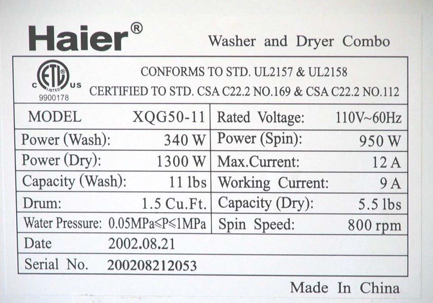
WASHER DRYER COMBO

  THIS IS A SINGLE FRONT LOAD
 THAT BOTH WASHES AND DRIES

            Features:

              Portable
          110v Operation
        Non Vented Drying
      Multiple Wash Options
Economical – Low Water Consumption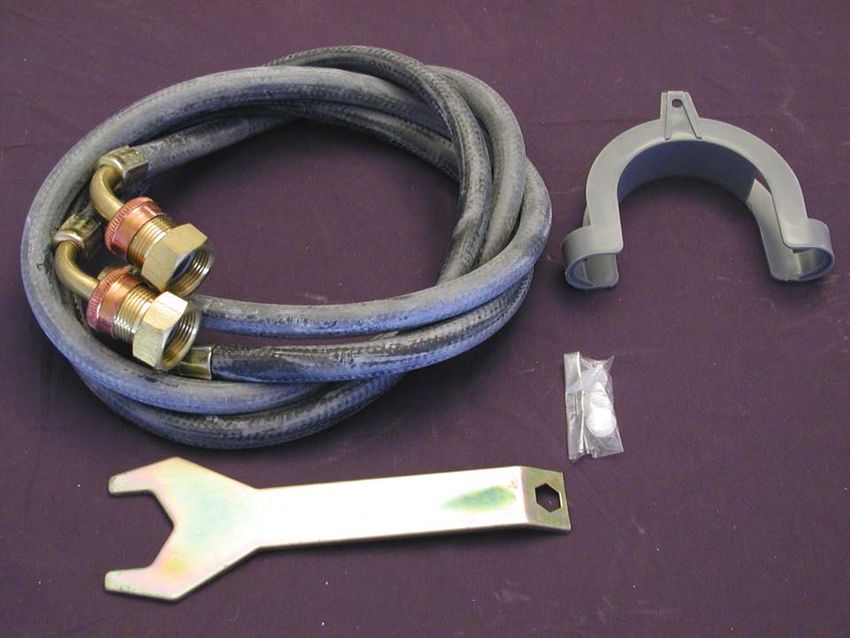
SPECIFICATIONS

       FRONT LOAD
WASHER DRYER COMBO UNITS

                           .

                           .
SPECIFICATIONS
  FRONT LOAD
    WASHER
      or
 DRYER UNITS

                 .
                     .

                 .
DATA TAG
INSTALLATION

    An owners guide, product
registration, hoses with adapters,
  drain goose neck, and plastic
plugs are packaged in each unit.

   A wrench may be packed in
         some models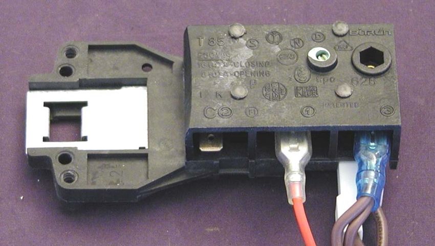
INSTALLATION

  Castors on the bottom allow the unit to be moved for easy
                    installation or cleaning
Use care when lowering the castors as the entire weight of the
 machine is being lowered and the handles can spring inward
                     and pinch the fingers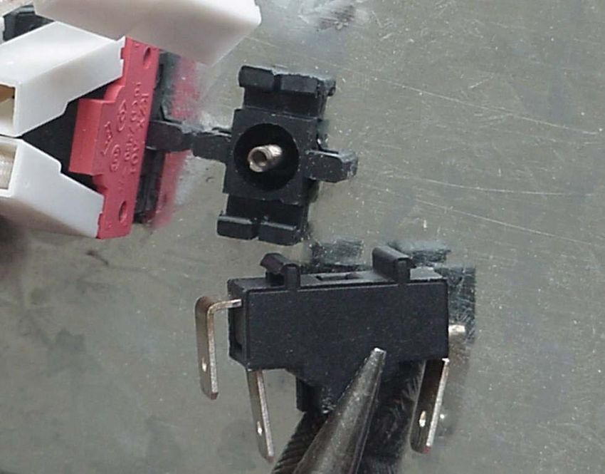
Once the unit is in the location
                                      INSTALLATION
where it is to be installed, remove
  the 3 shipping bolts and the
          rubber spacers.

   The rubber spacers can be
 reached by removing the back
             panel

      3 SHIPPING BOLTS
Put the 3 plugs from the Owners
  Package in the 3 bolt holes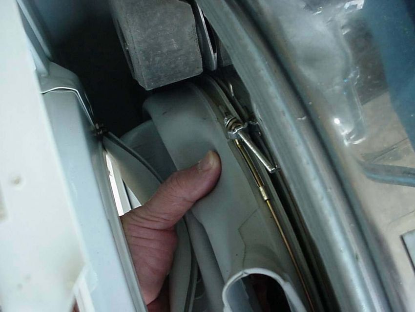
INSTALLATION

LOCATION:
      Dry, Out of direct sunlight
      Firm, Level surface
      Above Freezing Temperature

NOT ON CARPET – AIR CIRCULATES UNDER THE UNIT

ELECTRICAL:
      120volt 60 cycle
      Properly Grounded Polarized Wall Plug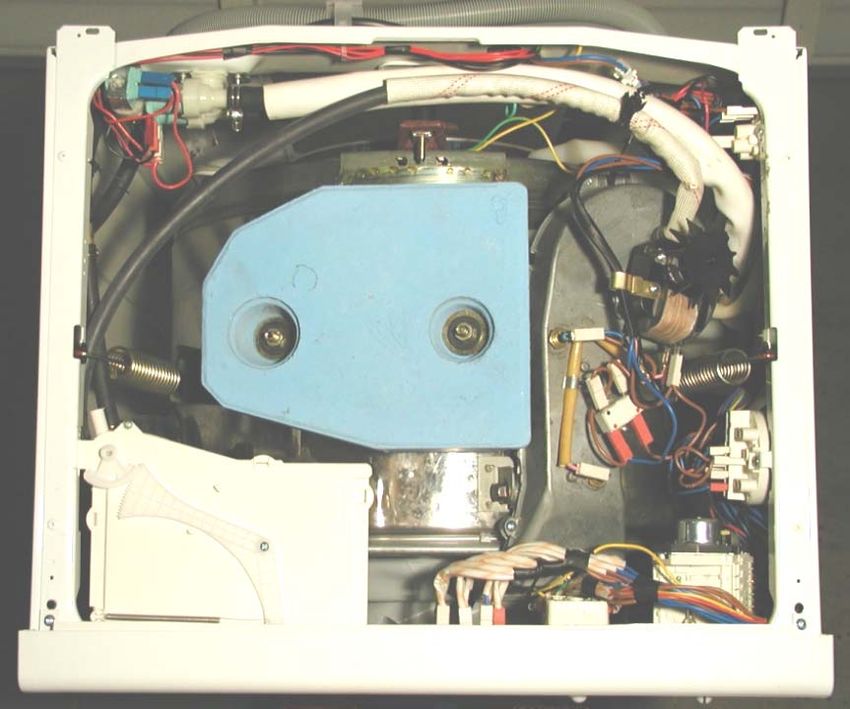
INSTALLATION

             Use only supplied hoses and adaptors to
               To prevent overflow of the dispenser

                                   The RED ends of the hoses are metric.
                                   The opposite ends are NPT hose fittings

               Flow Restrictor
Attaches to the metric threaded water valves
      to prevent overflow of dispenser
INSTALLATION
DRAIN HOSE
Place the drain hose into a sink or drain pipe
at least 1 ½” in diameter
Use the “GOOSE NECK” to hold it in place
If less than 37 1/2” high, route it through the clip
on the back of the washer
40” High Maximum Drain HeightINSTALLATION
LEVELING
Adjust all 4 leveling legs on the bottom
of the washer to prevent movementTHE UNIT HAS MANY STICKERS AND LABELS
TO ASSIST THE HOME OWNER IN OPERATING
THEIR NEW COMBO WASHER DRYER
LET’S TAKE A CLOSER LOOK…FEATURES OF THE XQG50-11
NOTE: Free installation program
has been discontinued
However, If the customer’s unit
has this label, we will pay the
installation chargesFRONT OPERATING
AND WARNING
LABELSBUTTON TRAP
WARNING:
Water will be released when
the Button Trap is opened
It normally needs to be
cleaned only a few times a
yearOPERATING INSTRUCTIONS
To assist the owner,
a large operating guide
is affixed to the top
panelCONTROLS XQG50-11SU
DISPENSOR OPERATION
                         XQG50-11SU
                                          Softener
 Pre-Wash
(No Liquid)
                                                 Bleach

                                Wash

 Pull the drawer open to fill the
         dispenser cups
CONTROLS
XQG65-11SU
The Buttons “pop”
in and out
by pushing on the face
of the dialDISPENSOR OPERATION
XQG65–11SU
Pull the drawer open to fill the
dispenser cups
Softener
Wash
(Liquid)
Pre-Wash
Pre-Wash
(Liquid)
(Liquid)OPERATING INFORMATION
XQG50–11SU
USE LESS DETERGENT – LOW SUDSING PREFFERED
FOR SMALL TO MEDIUM LOADS THE “SAVE WATER”
BUTTON CAN BE PUSHED
WATER TEMPERATURE IS AUTOMATICALLY SELECTED
COTTON CYCLE: PREWASH - COLD
HEAVY - HOT
NORMAL - WARM
LIGHT - COLD
SYNTHETIC CYCLE: HEAVY - WARM
NORMAL - COLD
LIGHT - COLD
WOOL CYCLE: ALL - COLDOPERATING INFORMATION
XQG50–11SU
For delicates,the ‘NO SPIN”
button can be depressed.
This will also prevent the unit from going
in a dry cycle
SELECT PROPER CYCLE – Always turn unit off and turn knob clockwise
COTTON: Water level is to lip of wash basket – just below door
HEAVY – HOT WATER AND 120 MINUTE CYCLE
Agitates about 12 sec. – Pause 8 sec. – Reverse 12 sec.
NORMAL-WARM WATER AND 80 MINUTE CYCLE
LIGHT ----COLD WATER AND 60 MINUTE CYCLE
Agitates about 4 sec. – Pauses 15 sec. – Reverse 4 Sec.
PREWASH FOR EXTREME SOIL – COLD WATER THEN
GOES INTO HEAVY CYCLE
If the “NO SPIN” button is selected, the unit drains and switches off
after the wash cycle and will not go into a spin or dryOPERATING INFORMATION
XQG50–11SU
SYNTHETIC: WATER LEVEL TO BOTTOM OF DOOR GLASS
HEAVY—WARM WATER FOR ABOUT 59 MINUTES
NORMAL-COLD WATER FOR ABOUT 42 MINUTES
LIGHT-----COLD WATER FOR ABOUT 33 MINUTES
AGITATES ABOUT 11SEC.-PAUSE 8 SEC.-REV. 11 SEC.
IF THE “NO SPIN” BUTTON IS SELECTED THE UNIT STOPS
AFTER IT WASHES AND DRAINS
IF THE “NO SPIN” IS NOT SELECTED AND NO AUTOMATIC
DRYING IS SELECTED – THE UNIT STOPS IN THE
“SOAK/PAUSE” SETTING.
YOU MUST EITHER:
A)DRAIN ONLY – PRESS “ON OFF” TO TURN OFF – ADVANCE TIMER TO
“DRAIN” – PRESS “ON OFF” AGAIN TO OPERATE UNIT
B)DRAIN AND SPIN – PRESS “ON OFF” TO TURN OFF – ADVANCE TIMER
TO “SPIN” – PRESS “ON OFF” AGAIN TO OPERATE UNITOPERATING INFORMATION
XQG50–11SU
WOOL: WATER LEVEL ABOUT 1/3 OF THE WAY UP THE GLASS DOOR
DELICATE CYCLE – COLD WATER – SLOWER SPEEDS IN
AGITATION AND SPIN – ABOUT 32 MINUTES TOTAL
AGITATES ABOUT 4 SEC.-PAUSE 15 SEC.-REV. 4 SEC.
WILL NOT AUTOMATICALLY GO INTO DRY CYCLE
IF THE “NO SPIN” BUTTON IS SELECTED THE UNIT STOPS AFTER
IT WASHES AND DRAINS
IF THE “NO SPIN” IS NOT SELECTED– THE UNIT STOPS IN THE
“SOAK/PAUSE” SETTING.
YOU MUST EITHER:
A)DRAIN ONLY – PRESS “ON OFF” TO TURN OFF – ADVANCE TIMER TO
“DRAIN” – PRESS “ON OFF” AGAIN TO OPERATE UNIT
B)DRAIN AND SPIN – PRESS “ON OFF” TO TURN OFF – ADVANCE TIMER
TO “SPIN” – PRESS “ON OFF” AGAIN TO OPERATE UNITOPERATING INFORMATION
XQG50–11SU
WASH SPEEDS:
Approximately 58 RPM
SPIN SPEEDS:
WOOL: Approximately 105 RPM
COTTON: Starts slow and goes to 800 RPM
SYNTHETIC: Starts at 105 RPM then goes to 500 RPM
All spins are counterclockwise from the front of the cabinet
DRYER:
About 12 sec. – Pause 6 Sec. – Reverse 12 sec.
Approximately 58 RPM
Note: Speeds and times are approximateOPERATING INFORMATION
XQG50–11SU
DRYER OPERATION
Manual Operation
Load machine with wet clothes and select HEAT,
the amount of time, then depress the “ON OFF” button.
Note: The Washer cycle selector must be set to a DRY/OFF Position
Automatic Operation
Set Dryer Control to desired time and heat before washing.
The Dryer comes on after the wash cycle completes.
Note: The dryer will not come on if
“WOOL” or the “NO SPIN”
button is selectedDRYER INFORMATION
This is a Condensing Dryer
--Not Vented to the Outside
--110 volt operation
--Takes longer to dry
--For Heavy Loads it is best to split into 2 loadsCool dry air is pushed over the
heater by the fan.
Cool moist air exits
the rear of the
drum and passes
through a mist and COMBO
film of cold water Hot dry air
LAUNDRY
enters drum
Moisture in the air THEORY above the
condenses in the OF door glass.
cold water OPERATION
Water collects in
sump and is
pumped out
Hot dry air passes through clothes
as they tumbleMACHINE COMPONENTS
OVERVIEWACCESS
Remove Screws
under each rear corner to gain access
to most machine components
ScrewsACCESS
Pull Top
slightly to rear then lift offFRONT LOOKING STRAIGHT DOWN
Fill Valves Pump
Pressure
Switch
Dryer
Blower
Motor
Thermal
Limit Fuse
Dual
Thermostat
Dispenser
Wash
Pressure
Switch
Selector Switches Dryer Timer Washer TimerWATER LEVEL PRESSURE SWITCHES
Rear AND HEATER COMPONENTS Front
SIDE VIEW
Dry
Pressure
Switch
Wash
Dryer Pressure
Blower Dual
Switch
Motor ThermostatWATER LEVEL PRESSURE SWITCHES
AND COMPONENTS
Rear Front
SIDE VIEW
Pump
Pressure
Switch
Fill
Pressure tube from air Pressure
dome feeds both Switch
pressure switchesWATER LEVEL PRESSURE SWITCHES
AND COMPONENTS
Dry Pressure Fill Pressure
Switch Switch
Y
Fitting
Pressure
Switch
Tubing
Air Dome
!!! CAUTION !!!
DO NOT APPLY PRESSURE
OR FORCE TO PRESSURE
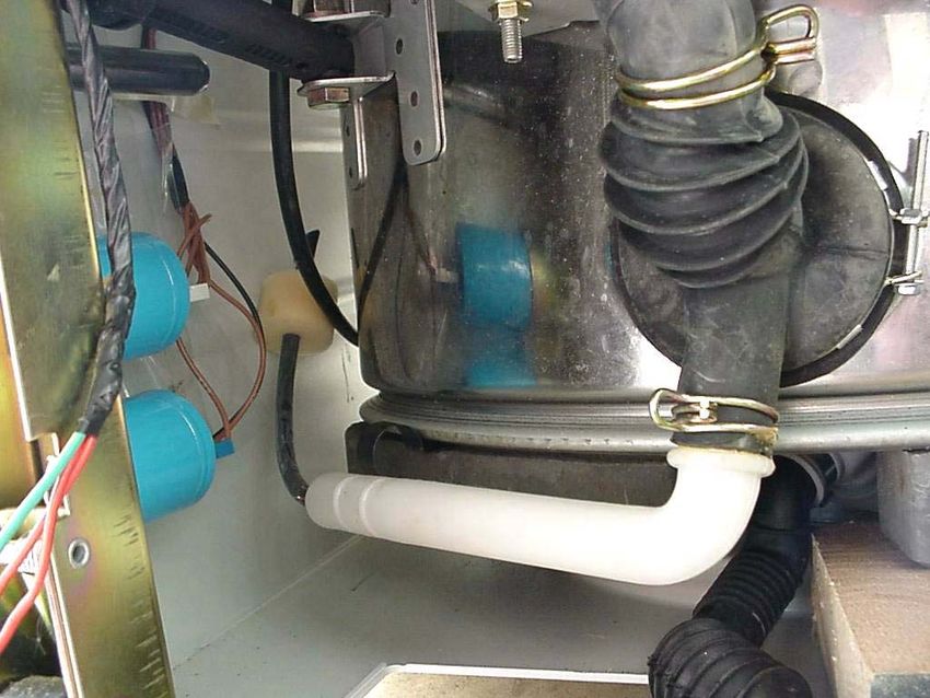
SWITCHES.TUB DRAIN AND AIR DOME
Drain from
tank bottom
Tubing to Y and
Pressure Switches
Air Dome
The Air Dome and Pressure Tubing
to the Pressure Switches is
accessible through the bottom of
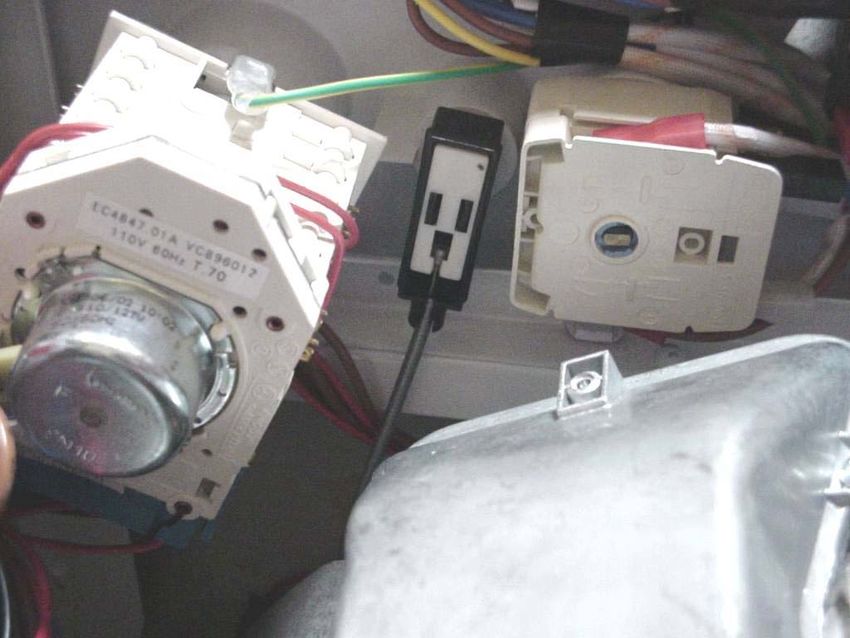
the unit.TIMERS AND SELECTOR SWITCHES
Washer Timer Dryer Timer Selector Switches
Front
PanelCONTROL PANEL ACCESS
Remove 2 Screws
Tilt the control panel down and
release the bottom tabs by
lifting upPUSH BUTTON
SELECTOR SWITCH
“WINGS” on each side must
be folded back for removalPUSH BUTTON
SELECTOR SWITCH !! Service Tip !!
Grasp the defective switch
twist and remove
Replace only the switch BODY
from the replacement
1
2
3WASHER TIMER REMOVAL
Remove these screws to remove Remove these
Timer and Mounting Bracket screws to remove
Timer OnlyTIMERS
Note Letters are on the other side
Color Code Dots
Dryer TimerWASHER TIMER
Wiring Harness
Timer Connections are identified with letters
Each plug and connector is numbered
Example: Wire C6
would be the 6th wire on the red plug
C is the red connector
identified by the red dot on
the other side of the timerWASHER TIMER
Wiring Harness
The connectors can be
removed more easily if
all are removed at one
time.
Squeeze the side
releases on each plug
and start them off –
Then remove the entire
bundleTIMER KNOB
and
DISPENSER SERVICE
for the
XQG50-11SUWASH TIMER KNOB REMOVAL
XQG50-11SU
Carefully “rock” the knob off the the timer.
It is held in place with tabs on the inner surface of the knobDRYER TIMER XQG50-11SU Pull knob straight off then remove screws
DISPENSER
                          XQG50-11SU

Remove the Dispenser
  Drawer by pulling
     straight out

  There will be slight
resistance when pulling
 past the raised stops
DISPENSER
Operation
The dispenser is XQG50-11SU
operated by a control Pivot Arm
rod from the timer camDISPENSER REMOVAL
XQG50-11SU
Remove screw and pivot arm
to allow control to be released
Note alignment of pivot arm
with diverter camDISPENSER REMOVAL
XQG50-11SU
Remove hoses attached to back
Timer Cam Follower
Removes screws and
attaches to control rod
Then pull dispenser forwardCONTROL ROD AND CAM FOLLOWER
XQG50-11SU
Timer Cam Follower
attaches to control rod
Follower Pin
rides inside of cam
Back View
of camTIMER KNOB
and
DISPENSER SERVICE
for the
XQG65-11SUKNOB and TIMER REMOVAL
XQG65-11SU
Carefully pry cap from knob
Single screw under cap
holds knob in place on
timer shaft
Screws release timer from
control panelDISPENSER REMOVAL
XQG65-11SU
Remove screws on top and
bottom of dispenser housing
and remove from the back of
the control panel
Dispenser cup is removed
by removing hinge pin
Water is routed to the
different cups by the use of
the multiple fill valvesThe Remaining Presentation
Covers all Models
XQG50 XQG65BOOT REMOVAL
Outer Retaining Wire
Release wire by
removing single screw
Unhook ends of wire and
remove wire. Boot can then
be rolled off of the front lipBOOT REMOVAL
Inner Retaining Wire
Release tension by
removing screw clamp
Easy access is gained by
removing
Dispenser and Control Panel
and through
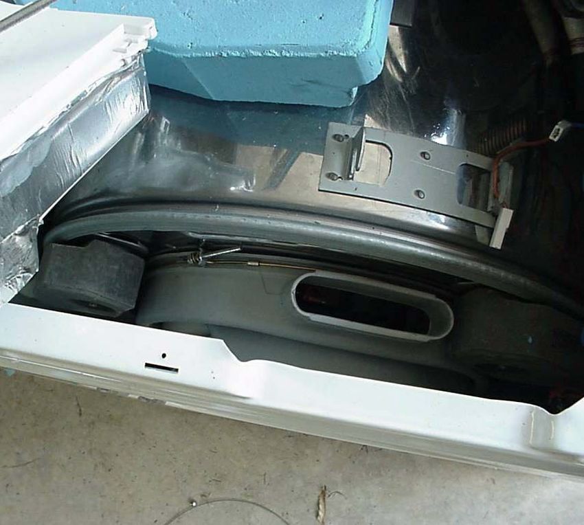
Outer Boot openingDOOR LATCH MECHANISM
Mechanism is held in
place with 2 screws
from the front
Access the switch from
the top,
behind the front panel.
Push the tub back for
easier access.DOOR LATCH MECHANISM
XQG50-11SU
Manually open
by using hook in hole
to slide latch open
Front View Back View
towards front towards tub
panelDOOR LATCH MECHANISM
XQG65-11SU
Push Button
on front panel Cable activated from
button to switch
Remove the cable by pulling the
outer wrapper straight out of the
Door Latch
either switch body the removing the
inner cable from the activatorDOOR LATCH MECHANISM
XQG65-11SU
Manually open
by using hook in hole
to slide latch open
Back View
towards tubWATER VALVES
Triple Cold
used on XQG65-11SU models
Single Hot
Dual Cold
XQG50-11SUWATER VALVES
Dual Cold
High Pressure XQG50-11SU
Hose to
Condensing Tank
Water Line
to Single Hot
DispenserDRY CYCLE
Heater Components
Heater Element Terminals
One Time
Thermal Fuse
Dual Temp ThermostatDRY CYCLE
Thermostat & Heater
An O-Ring is used to provide Retaining Nuts holding metal
an air tight seal on the tube heater in place
thermostat
Metal Tube HeaterDRY CYCLE
Thermal Fuse
One Time Thermal Fuse
removed from protective shield
The thermal fuse is in series with
the heating elementDRY CYCLE
Heater Manifold
Screws and Clips hold the heater manifold halves together.
Gasket provides
airtight sealDRY CYCLE
Blower Wheel
The Blower Wheel is held in place with a collet type locking sleeve.
The nut is clamping a split bushing tight on the motor shaft. Loosen
but do not remove the nut. Tapping with a soft hammer will release
the bushing. Remove the nut and pull the fan blade off.
THIS IS A LEFT HAND THREADED NUT
RemoveDRY CYCLE
Heater Manifold Base
Outlet of heater manifold goes Gasket mating to
into boot above the door condensation tank
Condensation
TankDRY CYCLE
Condensation Tank
Water Inlet
For Condensation
Dry Cycle
The Water Restrictor
Is located in this
fitting
Three nuts to
remove tank
Drain OutletDRY CYCLE
Condensation Tank
Removed from Tank
Three nuts to
remove tank
Condensate Tank Air Inlet
showing screen in outer drum
Condensate Tank
can be removed without removing
outer tub from cabinetDRY CYCLE
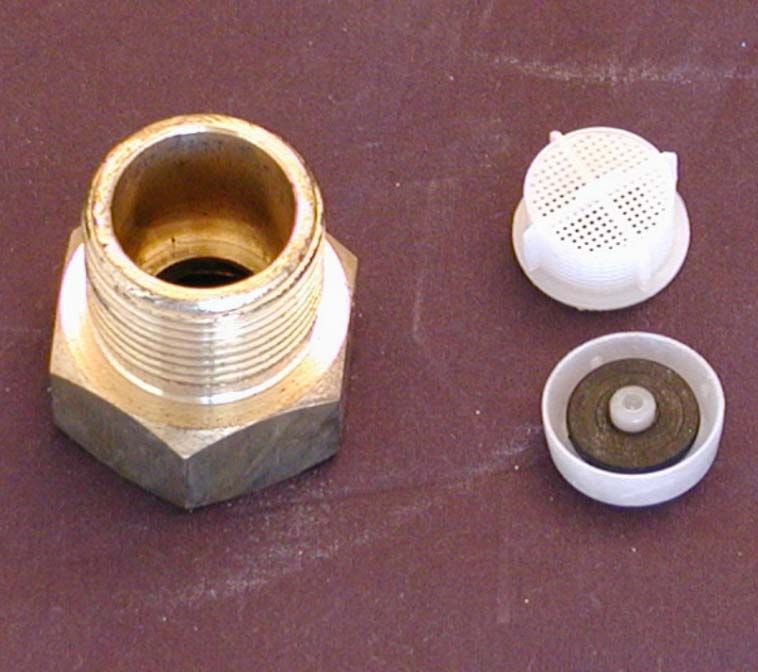
Water Restrictor
The water restrictor body is keyed for
proper installation.
Condensate and cooling water is
pumped out, cycling on the dryer
pressure switch.
Restrictor
Body
Flow
RestrictorDRY CYCLE
Operation To Drain
The tank has been cut in half
for this picture
Air Flow Water Flow
Mist and film
of water
Flow
Restrictor
Inlet from
drum
To DrainBOTTOM VIEW
Many components are easily Motor
Pressure
accessible through the bottom
Switch
of the unit.
Air Dome
Drain
Outlet
Trap
Body
Pump & Motor
AssemblyPUMP & TRAP
Remove 2 screws from the
trap and 2 bolds from the Removal
under kick-panel
Unhook the wiring harness
and hoses
Remove pump and housing
from bottom
2 Screws
Screw holding kick panel in place
2 Bolts holding trap
housing in placePUMP & TRAP Assembly
REAR ACCESS PANEL
Rear Access to Pulley, Belt
and other mechanical parts

                                        Slot for belt
                                          tension
                                        adjustment
PULLEY & TUB BEARINGS
Metric Allen Wrench
Reinstall spacers
when replacing
pulleyPULLEY & TUB BEARINGS
3 bolts hold the yoke in place.
It is easily removed through the
top and back panel.
The yoke and bearings come as
an assembly.TUB BEARINGS & SEAL
Water Seal contacts the Brass Bushing on the shaft
outer tank for water tight contacts the inner lip of the
seal sealINNER TUB
Bushing rides in
the inner lip of the
water seal
Inner tub is a
unit assemblyOUTER TANK ASSEMBLY
REMOVAL
Tub bearings and seal are easily serviced from the back making it highly
unusual to remove the outer tank and drum from the unit.
If these components must be serviced, remove the motor and counterbalance
weights before removing tank through the top of the cabinet.OUTER TANK ASSEMBLY
Disassembly
Remove tank front after removing clamp ring
Clamp Ring
Metric Allen
WrenchOUTER TANK ASSEMBLY
Service
When re-installing tank front clamp ring, lightly tap the ring around
the circumference to help seat the ring and draw the clamp tight.
Gasket on inner
lip of tank frontOUTER TANK ASSEMBLY
Service
Screen over outlet to
condensing tankMOTOR ASSEMBLY
Service
Adjusting slide
Motor is held in place with
2 through bolts with nuts
on the back
Electrical quick
connectorCAPACITORS AND
MOTOR CONTROLLER
The Motor Control Board and
Capacitors are on the right side of Front
the bottom of the cabinetMOTOR CONTROL
The motor has 2 sets of windings – one for
each direction of rotation.
Each winding uses its own capacitor
Feedback from a generator
on the motor controls the spin
speedI1 Power Switch EVF, EVP Cold Water Valve
I2 Load Switch PA, P1, P2 Pressure Switch
I3 Spin Switch TM Timer Motor
I4 Soak Switch MTA Dryer Timer Motor
L Line MC, ML Motor
N Neutral PS Drain Pump
G Ground PCB Speed Module
MR Door Lock C1, C2 Capacitor
EVA Cold Water RA Heat Element Dry
Valve Dry FE, FD ThermostatI1 Power Switch EVF, EVP Cold Water Valve I2 Load Switch PA, P1, P2 Pressure Switch I3 Spin Switch TM Timer Motor L Line MC, ML Motor N Neutral PS Drain Pump G Ground PCB Speed Module MR Door Lock C1, C2 Capacitor
THANK YOU FOR YOUR PARTICIPATION
             IN THE
        COMBO LAUNDRY
         PRESENTATION

       Parts and Service Information
               is available at
       www.haieramericasupport.com
You can also read