Evaluating the Load-Bearing Capacity of a Section of the Orenburg-Zainsk Main Gas Pipeline Using Static and Cyclic Loading Methods
←
→
Page content transcription
If your browser does not render page correctly, please read the page content below
E3S Web of Conferences 225, 01012 (2021)                                                                https://doi.org/10.1051/e3sconf/202122501012
Corrosion in the Oil & Gas Industry 2020

       Evaluating the Load-Bearing Capacity of a Section of the
       Orenburg-Zainsk Main Gas Pipeline Using Static and Cyclic
       Loading Methods
       Mekhrali M. Aliyev1,*, Sergey P. Zaytsev2, Zulfiya F. Ismagilova1, and Minsariya M. Bayburova1
       1Almetyevsk State Oil Institute, 423450, Lenin street, 2, Almetyevsk, Russia
       2Almetyevsk Linear Production Department of Main Gas Pipelines, Gazprom Transgaz Kazan LLC, 423450, Bugulma trakt,
       Almetyevsk, Russia

                      Abstract. This paper examines the operability of the Orenburg-Zainsk main gas pipeline, which has been
                      in operation since 1971 and has various general defects, as well as specific defects such as internal
                      corrosion-induced delaminations and blisters of various geometric shapes. The design parameters of the
                      gas pipeline section and the characteristics of the pipe metal have been studied. Hydraulic tests were
                      performed on the pipe fragments in the form of sample barrels to determine the load-bearing capacity in
                      order to evaluate the operability of the gas pipeline. There were three types of sample barrels: those made
                      from pipes with internal blistering and delamination, from pipes with invisible defects, and from
                      emergency stock pipes. A cyclic test was performed on one sample according to the developed method.
                      The theoretical analysis of the load-bearing capacity of the gas pipeline was performed according to the
                      accepted design model.

       1 Introduction                                                         pipes fabricated in Germany and France – on the II
                                                                              category sections. The pipes are made of low-carbon
       Today a large proportion of main gas pipelines has been                low-alloy steel with a 0.18...0.20% carbon content, with
       in operation for more than 30 years. A number of                       an ultimate strength of at least 520 MPa, a yield strength
       factors, such as certain violations in the manufacturing               of at least 300 MPa, and an impact strength of 500 kJ/m2
       technology and methods of construction and operation,                  at minus 400C. The pipes are made of normalised sheet.
       can lead to impaired performance of gas pipelines.                         The main design specifications of the section under
           The article discusses the Orenburg-Zainsk gas                      consideration: design pressure – 5.4 MPa; allowable
       distribution main, which was put into operation in                     operating pressure – 3.4 MPa; pipeline diameter – 1,020
       September 1971, as an example. With a glance to such a                 mm; and wall thickness – 14-16 mm.
       long operation period, the general condition of the main
       requires a detailed examination, including evaluation of
       the operability of individual sections of the linear part
       along with addressing practical issues related to load-
       bearing capacity and operational reliability of the
       pipeline as a whole.
           Given the nature of the delaminations observed and
       resulting blisters on the sections of the gas pipeline in
       question, which are several kilometres long, the pipeline
       load-bearing capacity should be assessed in the
       framework of solving the following tasks:
       - investigation of the possibility of the pipe steel
       delamination during manufacturing;
       - study of the causes of blistering;
       - study of the effect of resulting blisters and                        Fig. 1. Defects in the form of delamination detected after
       delaminations on the gas pipeline load-bearing capacity.               testing a full-size pipe with internal blistering.
           The Orenburg-Zainsk gas pipeline supplies
       regeneration gases from mercaptan removal units mixed                     In 2016, a comprehensive flaw detection of the
       with purified gas to Zainsk SDPP (State District Power                 main's 376-479.6 km section was performed. During the
       Plant). This is a single-line buried gas pipeline                      gas pipeline comprehensive flaw detection, 2,264 defects
       constructed of 1,020x16 mm pipes from a Swedish                        of different kinds were detected on the section [1].
       vendor used on the I category sections and 1,020x14 mm                 Special attention was paid to such defects as blisters and

       *
           Corresponding author: iiii.iskandar@inbox.ru

  © The Authors, published by EDP Sciences. This is an open access article distributed under the terms of the Creative Commons Attribution License 4.0
  (http://creativecommons.org/licenses/by/4.0/).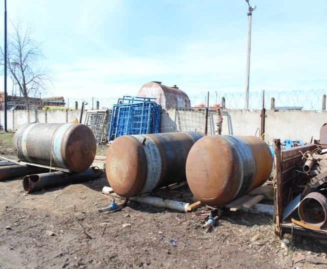
E3S Web of Conferences 225, 01012 (2021)                                                         https://doi.org/10.1051/e3sconf/202122501012
Corrosion in the Oil & Gas Industry 2020

       delaminations having various geometric shapes and sizes               For this reason, such defects as micro-cracks and
       detected during pig inspection and destructive hydraulic           micro-delamination in the metal can appear on the inner
       testing of a full-size pipe (Fig. 1).                              wall surfaces of such pipes.

       2 Causes of delaminations and blisters                             3 Conditions for the formation of a
       in the gas pipeline                                                blister inside the pipeline
       The cause of these blisters and delaminations can be               After the micro-delamination is formed in the pipe body
       attributed to the pipeline operating conditions at the             under normal operating conditions without any
       initial stage, when the raw wet gas produced was fed               significant temperature jump along the pipe wall
       directly into the pipeline. A jump in the gas pressure             thickness, the working pressure would help close these
       (from 12-13 MPa to the operating pressure) led to a                cracks. However, the temperature of pumped raw gas
       decrease in the gas temperature and a change in the                after reduction at the gas pipeline inlet decreases sharply,
       stress state of the pipe material. The temperature drop of         with the temperature delta approximately equal to 60°C.
       the pipe's inner and outer surface reached 600C, which             Annular temperature stresses also show a jump that can
       led to the delamination of the pipe steel structure and the        be calculated using the formula [5]
       loss of stability on the inner side as shown on the scheme
                                                                                                                          )
       (Fig.2).                                                                                               2(
                                                                                =                        3                  ,   (1)
                                                                                      3(1  )(        )

                                                                          where  is the modulus of elasticity of steel;
                                                                           = 2,1  10 MPa;
                                                                               – thermal expansion coefficient of steel,
                                                                           = 1,25 · 10 1/°;
                                                                                 ,      – inner and outer radii of the pipe,
                                                                          respectively.
       Fig. 2. Diagram of the pipe wall stability loss.                       If       = 50 cm, = 51,4 cm, the temperature
                                                                          compressive stresses of the inner section are equal to
           For this reason, a pipeline exposed to delamination             = 105 MPa, and those of the outer section to  =
       cannot deliver performance required by the design.                 104,5 MPa.
           To assess the load-bearing capacity of the gas                     Although the formula (1) is valid for thick-walled
       pipeline sections that have such defects, we can take the          pipes, in the case of a sharp temperature drop inside the
       first design model as a dome fixed on a yielding support           pipe, it can also be applied to thin-walled pipes. The
       ring. The cross section of the dome corresponding to the           deviation does not exceed 15%.
       initial point of delamination should be taken as the                   Taking into account the conditions for the formation
       yielding ring.                                                     of delaminations during pipe manufacturing, blistering
           The design model is assumed in order to calculate the          may be caused by a compressive stress  .
       internal pressure that leads to collapse of the blisters and           Taking the area of the inner pipe section as a strip,
       exhaustion of the pipeline load-bearing capacity.                  we can calculate the critical stress sufficient for the loss
           After processing on the edge-banding and pipe-                 of its stability by the formula [6]
       bending machines, the pipe wall roundness is
       insufficient, and the pipe diameter is by 0.5-1.5% less
                                                                                           =                 ,                 (2)
       than required. To achieve the required diameter and the                                      12(1     )
       maximum roundness of the pipe, expanding is
       performed.                                                         where  is the thickness of the delamination,  = 7 ;
           The calculations [2-4] show that in the case of a pipe               – Poisson's ratio, for steel = 0.3;
       with a 1,420 mm diameter and a yield strength of 500                    – modulus of elasticity of steel;  = 2.1  10 MPa;
       MPa the maximum circumferential stresses in the pipe                    – ratio that depends on the blistering length and

       wall caused only by expanding exceed the yield strength            width, at = 2,  = 10.

       of the metal. For this pipe, the sum of residual stresses              Substituting the parameters in formula (2), we obtain
       after the pipe-bending machine and extreme
                                                                           = 106 !.
       circumferential stresses during expanding inside the pipe
                                                                              Thus, the temperature stress  = 105 ! can
          b        b is the ultimate strength. The
                                                                          cause the formation of a blister. To this end, it is
       maximum circumferential stresses on the inner and outer
                                                                          assumed that the internal operating pressure during the
                b    b,
                                                                          formation of a blister is taken up by the external layers
       respectively, that is, the maximum shear stresses inside
                                                                          of the pipeline up to the microlamination layers formed
          t, since
                                                                          in the process of the pipe manufacturing.
       according to the Saint Venant-Tresca criterion,
       if 1  b, 3=0, that !max=0.5 (1.254-0) b=0.627 b.

                                                                      2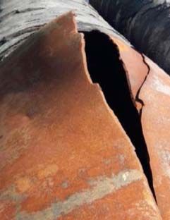
E3S Web of Conferences 225, 01012 (2021) https://doi.org/10.1051/e3sconf/202122501012
Corrosion in the Oil & Gas Industry 2020
4 The sequence of blister formation and barrels had no visible defects, and no signs of
collapse delamination were found on them after destructive
hydraulic pressure testing.
Figures 3 and 4 show the mechanism of the emergence Calculations based on the membrane theory
of internal defects in the form of blisters in a gas pipeline according to the barrels' geometric parameters, as well as
under compressive and tensile stresses stemming from a the results of flat samples testing showed an insignificant
temperature rise on the gas pipeline wall. deviation from the certified strength parameters.
Figure 5 shows a scheme of the collapse of the The test performed on a full-size Orenburg-Zainsk
blisters under the ultimate pressure during hydraulic pipeline with internal delaminations and blistering
testing. revealed a fairly significant decrease in the pipe's load-
bearing capacity (Fig. 1) up to 9.2 MPa.
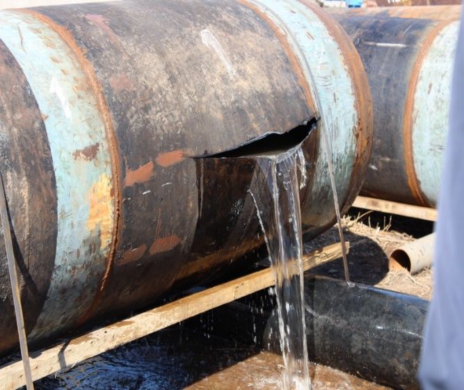
Hydraulic tests of pipe fragments in the form of
sample barrels were performed to determine the load-
bearing capacity for evaluating the operability of the gas
pipeline (Fig. 6). There were three types of sample
barrels:
pipes from the emergency stock – collapse pressure
was 16.8 MPa, which corresponds to an ultimate strength
of 560 MPa, with 570 MPa according to the certificate;
Fig. 3. Scheme of the emergence of compressive and tensile
stresses on the gas pipeline wall. pipes with invisible defects – pressure was 13.2 MPa,
which corresponds to an ultimate strength of 440 MPa.
Strength reduced by 23% over the period of operation;
pipes with internal corrosion-induced delamination –
pressure was 9.6 MPa, which corresponds to an ultimate
strength of 320 MPa. The decrease is 44% from 570
MPa.
Fig. 4. Scheme of the formation of internal gas pipeline
blisters.
Fig. 5. Scheme of the collapse of the blisters by increasing the
internal pressure in the gas pipeline.
5 The change of the ultimate strength of
steel in time
Pipeline steel loses its original strength to some extent in
the areas where delamination begins. It is quite a
difficult task to detect exactly the point at which the
destruction begins. To solve this problem, we can make
samples cut from the areas marked by blistering. By
testing these samples, we will reveal the proportion of
impaired strength.
The load-bearing capacity of the pipeline with
internal delamination and the formation of blisters,
encountered in the case examined, can be found by
means of hydraulic testing of barrels cut from the
sections with such defects. Tests may be also performed
on the barrels without similar visible defects. By
comparing the results, we can indirectly obtain the
ultimate strength of steel pipes with delaminations. Fig. 6. Sample barrels before and after hydraulic testing.
In the paper [7], the load-bearing capacity of two
main gas pipelines after many years of operation was To study the behaviour of the detected defects during
evaluated by testing the internal pressure of fragments of the subsequent operation of the gas pipeline, a number of
full-scale samples (barrels), as well as flat elements cut tests were performed on the defective pipe using the
from the dismantled sections of pipes. The sample cyclic loading method. For this purpose, a barrel was
made with a defect in the inner wall surface. An
3
E3S Web of Conferences 225, 01012 (2021)                                                        https://doi.org/10.1051/e3sconf/202122501012
Corrosion in the Oil & Gas Industry 2020

       additional pipeline system with a pressure gauge and a            where = ; # = 30.13 cm, h = 4 cm, t = 0,7 cm.
                                                                                     <
       tap was installed on the test barrel at a safe distance.
                                                                            According to Fig. 4, we obtain $%&'* =
           The pressure was initially increased to 6 MPa using a
                                                                         0.867, &+-'* = 0.498,  = 8.57.
       hydraulic pump; after 24 hours it was lowered to 5 MPa;
                                                                            Taking into account only  , the dome strength
       then after another 24 hours — to 4 MPa, etc.
                                                                         condition is calculated as
           At the next stage, the pressure was increased to 7
       MPa and the test was repeated. After testing at 8 MPa
       and 9 MPa, the sample was destroyed by a pressure of                                          =  ,                     (5)
                                                                                                  @
       9.5 MPa.
           Thus, the cyclic loading performed according to the                          1
       described scheme did not affect the load-bearing                  where @ =          .
                                                                                          6
       capacity of the sample.                                               Substituting (3) in (5) we find the pressure at which
                                                                         the blister collapses
       6 Selection of the design model for in-                                                    2A
       pipe blisters with delamination                                                "=                            .           (6)
                                                                                                        1  $%&'*
                                                                                           3# $%&'*
                                                                                                          &+- '*
       Analysis of the external forms of in-pipe blisters, taking
       into account the absence of signs of deformation on the               Taking into account the metal fatigue in the support
       outer pipe surface, provides grounds for taking them as           section and the stress concentration, we assume A =
       thin-walled shells with different dimensions in plan. In          250 MPa, then " = 9.9 MPa.
       addition, we can also assume that the shells rest on                  If we assume that the inner pressure is taken only as
       yielding supports capable of moving horizontally as the           an outer strip with the thickness of B = 7 mm, the
       shell is loaded with pressure.                                    ultimate strength equal to the certified value, then the
           For the shell taken as mentioned above, we will               pressure leading to destruction will be
       adopt the design model as follows (Fig. 7).
                                                                                          2CDE B 2  570  0.7
                                                                                     "=         =              = 8 MPa.          (7)
                                                                                            F         100
                                                                             The difference between pressures calculated using
                                                                         the formulas (6) and (7) shows that at the time of the
                                                                         blister collapse and destruction of the pipeline, there is a
                                                                         short period of a cumulative effect of the blistering in the
                                                                         support zones and the base metal of the weakened cross
                                                                         section.

                                                                         7 Conclusions
                                                                         1. As a result of hydraulic testing of three sample
                                                                            barrels, the metal fracture pressures were found and
                                                                            the ultimate strength values of the pipe material were
                                                                            estimated.
       Fig. 7. The design model of shell loading.                        2. Cyclic tests of the sample barrels with internal
                                                                            delamination were performed using the developed
           The procedure for calculating such a shell can be
                                                                            method.
       found in [8].
                                                                         3. The stresses leading to the formation of blistering
           The accepted assumption of the supports yield should
                                                                            and the pressures needed for these blisters to collapse
       be considered fair, since stresses are concentrated in this
                                                                            were obtained with the use of the assumed design
       section, and it is the place where the maximum
                                                                            models.
       displacement will occur. Then the membrane theory can
                                                                         4. Upon the analysis of theoretical and experimental
       be applied in case of the assumed thin-walled shell.
                                                                            studies, we can conclude that, since the destructive
           The longitudinal bending moment is calculated by
                                                                            pressure (within 9.4-9.6 MPa) of pipes with internal
       the formula
                                                                            delamination exceeds the operating pressure of 3.4
                           "#          1  $%&'*                            MPa 2.76 times, further long-term operation of the
                     =      $%&'*            ,           (3)           gas pipeline with such defects is possible.
                           2            &+- '*

       where  is the coefficient determined by the formula              References
                                #:                                       1.   A.V. Mitrofanov, N.A. Gafarov, B.V. Kichenko,
                            = 8 93(1              ),        (4)             A.I. Rezvykh, V.A. Polozov, Analysis of the causes

                                                                              and nature of corrosion damage in the initial period

                                                                     4
E3S Web of Conferences 225, 01012 (2021) https://doi.org/10.1051/e3sconf/202122501012
Corrosion in the Oil & Gas Industry 2020
of the main gas pipeline operation. The Science and
Research Journal of All-Russia Research Institute of
Organisation, Management and Economy in Oil and
Gas Industry (NTZh VNIIOENGa). Corrosion
prevention and environmental protection, 10, 2-11
(1996)
2. V.N. Shinkin, Residual stresses during expansion of
steel pipes. Molodoy Uchyony [Young Scientist],
20, 88-93 (2015)
3. V.N. Shinkin, Elastoplastic deformation of a metal
sheet on three-roll mills. Molodoy Uchyony [Young
Scientist], 13 (93), 225-229 (2015)
4. V.N. Shinkin., A. P. Kolikov, V. I. Mokrousov
Calculation of maximum stresses in the pipe wall
during expansion taking into account the residual
stresses of the billet after the turbobend machine
SMS Meer. Rolling, 7, 25-29 (2012)
5. Structural resistance: Textbook for colleges, Under
the general editorship of the academician of the
Academy of Sciences of the USSR G. S. Pisarenko,
4th edition reprint, revised and updated (Vyshcha
Shkola [Higher School], Golovnoe Izdatelstvo
[Main publishing house], Kyiv, 696, 1979)
6. Yu.A. Shimansky, Naval Structural Mechanics
Handbook (Sudpromgiz, Leningrad, 251-252, 1958)
7. M.M. Aliev, R.R. Kantyukov, F.M. Mustafin, K.F.
Ulshina, Evaluating the load-bearing capacity of two
main gas pipelines after many years of operation by
tensile strength test. Gazovaya Promyshlennosyt
[Gas Industry], 12, 56-59 (2015)
8. B.N. Semochkin, Theory of elasticity (Publishing
House of Construction and Architecture Literature,
Moscow, 257, 1957)
5You can also read