Investigation on Dynamic Interaction of Multiple Clearance Joints for Flap Actuation System

Page created by Karl Johnston
 
CONTINUE READING
Investigation on Dynamic Interaction of Multiple Clearance Joints for Flap Actuation System
MATEC Web of Conferences 306, 010 01 (2020)                                                          https://doi.org/10.1051/matecconf/202030601001
ICMME 2019

         Investigation on Dynamic Interaction of Multiple Clearance
         Joints for Flap Actuation System
         Qi Wan, Geng Liu*, Shangjun Ma and Ruiting Tong
         Shaanxi Engineering Laboratory for Transmissions and Controls, Northwestern Polytechnical University, Xi’an 710072, China

                       Abstract. A dynamic simulation model of the flap actuation system is developed in this paper to analyze
                       the dynamic interaction behaviours of multiple clearance joints. The nonlinear contact force model and
                       modified Coulomb friction model are adopted in the four clearance joints to capture their motion modes,
                       including free flight mode, impact mode and continuous mode. The results show that there exists a strong
                       dynamic interaction between different clearance joints and one impact motion mode in a joint will
                       immediately affect other joints. And when the system reaches a stable state, the four clearance joints almost
                       appears the similar tendency due to the rigid connection. Therefore, in order to accurately predict the
                       dynamic responses of multibody system, it is essential for all joints to be modelled as imperfect ones.

       1 Introduction                                                         that in a mechanism with one clearance joint. Bai [3]
                                                                              studied the dynamic responses of satellite antenna dual-
       As flap actuation system is widely employed in the field               axis driving mechanism with two planar revolute
       of aircrafts, the demands of predicting the system’s                   clearance joints and developed an optimization method
       dynamic characteristics accurately are becoming                        to reduce the undesirable vibrations due to impact forces
       increasingly essential. The flap actuation system mainly               in clearance joints. Li [4] investigated the effects of the
       consists of an actuator, linkage mechanism, flight control             number of clearance joints on the dynamic
       surface and control system, which is a high precise                    characteristics of planar deployable structure based on
       position servo system [1]. The actuator receives the                   scissor-like element, and the results indicated that the
       control command of flight attitude of aircrafts, and then              motion in one revolute clearance joint will affect the
       produces force to drive linkage mechanism connected                    motion in the other clearance joint. However, the
       with control surface. At last, the aim of flight direction             combination motion modes between multi-clearance
       and attitude of aircrafts is accomplished. The output                  joints and some inner rules existing those modes are not
       angle of control surface is the main control target of the             revealed. Muvengei [5] and Ma [6] studied the
       flap actuation system, and its follow-up of the command                interaction and combination motion modes between
       signal directly determines the flight quality of aircrafts.            clearance joints, but the slider-crank mechanism only
       However, as the typical multibody mechanism with                       including four simple parts is always studied and there
       clearances, the linkage mechanism of flap actuation                    has been less investigated on the combination motion
       system has great influence on dynamic behaviors of                     modes and inner rules of aircrafts with imperfect
       aircrafts. Therefore, it is necessary to analyze the                   revolute joints.
       influence of joint clearance in the linkage mechanism on                   Therefore, in order to achieve the relationship
       the dynamic responses of flap actuation system.                        between system responses and combination motion
           Due to the manufacturing, assembly processes, and                  modes as well as dynamic interaction of clearance joints,
       wear errors, joint clearance is inevitable and always                  the dynamic characteristics of flap actuation system with
       leads to extraordinary negative effect on the dynamic                  multiple clearance joints are investigated in this paper,
       characteristic of multibody system. A number of                        which is significant for the dynamic simulation and
       researchers pointed that there is a strong dynamic                     analysis of transmission system in aerospace field.
       interaction between different clearance joints and all
       joints should be considered as non-ideal to accurately
       predict the dynamic performance of aircrafts and                       2 Modelling of flap actuation system
       spacecrafts. Li [2] established the dynamic model of the               with joint clearance
       spacecraft with large deployable solar arrays considering
       multiple clearance joints and studied the effect of joint              2.1 Model of revolute joint with clearance
       clearance on the satellite attitude under deployment
       disturbance. The results showed that system response                   The perfect revolute joint assumes that the centers of
       with two clearance joints is not a simple superposition of             journal and bearing are coincident all the time with only

         *
             Corresponding author: npuliug@nwpu.edu.cn

  © The Authors, published by EDP Sciences. This is an open access article distributed under the terms of the Creative Commons Attribution License 4.0
  (http://creativecommons.org/licenses/by/4.0/).
MATEC Web of Conferences 306, 010 01 (2020)                                                                 https://doi.org/10.1051/matecconf/202030601001
ICMME 2019

       relative rotation allowed, while the imperfect one means                    system is in the free flight mode and the contact force
       that there is a clearance between the centers of journal                    between journal and bearing is equalled to zero; (b) If
       and bearing.                                                                δ >0, the journal and bearing contact with each other and
           The clearance can be expressed by                                       the system is in the continuous contact mode; (c) If δ
                                                                                   changes from the negative to the positive, it means the
                                  c = rB − rJ                            (1)       two bodies are gradually approaching. Particularly, when
                                                                                   the relative penetration depth is equalled to zero, there is
           where c denotes the radial clearance and rB and rJ are                  an impact force between the journal and bearing and the
       the radii of bearing and journal, respectively.                             system is in the impact mode at that moment; (d) If δ
           The mathematical model of the revolute clearance                        changes from the positive to the negative, it indicates the
       joint is shown in Fig. 1. XOY donates the generalized                       two are gradually separating.
       coordinate system. OB and OJ are the centers of bearing
       and journal, respectively.
                                                                                   2.2 Contact force model
                                                                                   The “Impact-function” in multi-body dynamic software,
                                                   δ                               ADAMS [7-8], which is a nonlinear spring-damper
                             OB
                                      e                                            model considering the effect of energy dissipation
                                                                                   process and is widely employed by many researchers.
                                      OJ
                                                                                   Ma compared the simulation results of a slider-crank
                                                                                   mechanism with clearance joints, which the normal
                               rBO       rJO           Journal                     contact forces are respectively calculated by “Impact-
                                                                 t                 function” and the presented model, and the simulation
                  Bearing            Y
                                                                     n             results of those two models have a good agreement with
                                                                                   each other [6]. Khemili studied the dynamic behavior of
                                  O            X                                   a planar slider-crank mechanism with clearance by
       Fig. 1. Mathematical model of revolute clearance joint.                     “Impact-function” and verified the effectiveness of
                                                                                   contact force model by some experiments [9]. Chen
          As shown in Fig. 1, the eccentricity vector which                        analyzed the dynamic responses of a closed high speed
       connects the centers of bearing and journal (OB and OJ)                     and heavy load press and the “Impact-function” is
       can be written as [3-4]:                                                    employed to describe the contact response between the
                                                                                   journal and bearing. As the numerical results agree well
                                  e = rJO − rBO                          (2)       with the experimental data, it indicates that the “Impact-
                                                                                   function” can accurately describe the dynamic
           where rBO and rJO are the positional vectors of                         performance of the multibody system [10]. Therefore,
                                                                                   the “Impact-function” is used to predict the dynamic
       centers of bearing and journal in generalized coordinate
                                                                                   characteristics of contact-impact process for the flap
       system (XOY), respectively.
                                                                                   actuation system, and its equations can be given by [11]
           The magnitude of the vector e can be described as

                                  e = e Te                               (3)                                        Kδ 1.5               δ ≤0
                                                                                                                   2
          And the normal unit vector n at collision point can be                                         δ                 δ     
                                                                                   Fn =  Kδ 1.5 + cmax          3 − 2           δ 0 < δ < δ max (6)
       expressed as                                                                                                                
                                                                                                         δ max           δ max   
                                                                                                     K    δ 1.5
                                                                                                                 + c      δ               δ > δ max
                                     n = e/e                             (4)                                         max

           The tangential unit vector at the collision point can                       where δ is the relative penetration depth; δmax is the
       be obtained by reversing n for 90°.                                         maximal penetration depth; cmax is the maximal damping
           When the journal and the bearing come into contact                      coefficient, which is about one percent of the contact
       with each other, the relative penetration depth can be                      stiffness; K is the generalized contact stiffness and relate
       calculated with respect to e and c                                          to the material property and geometries of bearing and
                                                                                   journal, which can be expressed as
                                  δ =e−c                                 (5)
                                                                                                                 4                 RB RJ
           The motion of a journal in a bearing can be divided                                   K=                                                   (7)
       into three categories: the free flight mode, the contact                                           1 −ν B 1 −ν J         RB − RJ
                                                                                                       3       +           
       mode and the impact mode. The relative motion                                                      EB       EJ        
       relationship between the journal and the bearing can be
       accurately determined by the relative penetration depth δ.                     where RB and RJ are the radii of bearing and journal,
       There are several situations as follows: (a) If δ
MATEC Web of Conferences 306, 010 01 (2020)                                                                           https://doi.org/10.1051/matecconf/202030601001
ICMME 2019

           The frictional characteristics of the revolute                                   Fig. 3 shows that the existence of joint clearance has
       clearance joint is depicted by a modified Coulomb                                extraordinary obvious effects on the angular velocity and
       friction force model, and its formula is shown as [11]                           angular acceleration, which is obviously shaky around
                                                                                        the ideal curve. The constant value in angular velocity
                      − µ d ⋅ sign (vt )F                      vt > vd                 correspond to the zero angular acceleration and the
       Ft = − step( vt , vd , µ d , vs , µ s ) ⋅ sign (vt ) vs ≤ vt ≤ vd (8)
                                                                                       impulse type of angular acceleration means the abrupt
                                                                                       increase of angular velocity, which indicates that joint
                  step(vt ,−vs , µ s , vs ,− µ s )             vt < vs                 clearance will cause oscillation of the system movement
                                                                                        and lead to the worse system stability.
          where vt is the relative sliding velocity at contact
       point; vs is the critical stiction transition velocity; vd is                                             Table 1. Material properties.
       the friction transition velocity; µs is the static friction
       coefficient; µd is the dynamic friction coefficient.                                              Parameters         Young’s      Poisson’s             Mass
                                                                                                                            modulus        ratio              density
                                                                                                     Parts                   (GPa)          (/)               (kg/m3)
       3 Simulations and results
                                                                                                Actuator
       3.1 System properties                                                                     Rod1
                                                                                                                              209          0.269               7890
                                                                                          Bearing house 1,2,3,4
       The dynamic model of flap actuation system with four                                   Inertia plate
       clearance joins is shown in Fig. 2. The material
       properties of the system are shown in Table 1 and the                                      Rod2
       parameters used in the dynamic simulations are                                           Lever arm1                     45              0.33            2700
                                                                                                Lever arm2
       presented in Table 2. The “Impact-function” is adopted
       in the contact force model of clearance joints, and Gear                                      Shaft                    211              0.28            7700
       Stiff integrator (GSTIFF) is chosen in ADAMS/Solver.
       During the simulation, the integration tolerance is 0.001                              Table 2. Parameters used in the dynamic simulations.
       and the step size is 0.001s.
                                                                                         Parameter                      Description                   Value      Unit
       3.2 Dynamic interaction                                                                δmax           Maximal penetration depth                0.01       mm
                                                                                              µs                 Static friction coefficient          0.01        /
       This section presents the dynamic interaction
       phenomenon by analyzing the influences of clearance on                                 µd            Dynamic friction coefficient              0.01        /
       the dynamic responses of the flap actuation system. The                                 vs            Stiction transition velocity              0.1      mm/s
       command of actuator’s output displacement is defined as                                 vd            Friction transition velocity              10       mm/s
       10 mm with a constant frequency equal to 4 Hz, and size
       of the radial clearance equals 0.1 mm with the bearing
       diameter as 15 mm. The total simulation time is 0.5 s.

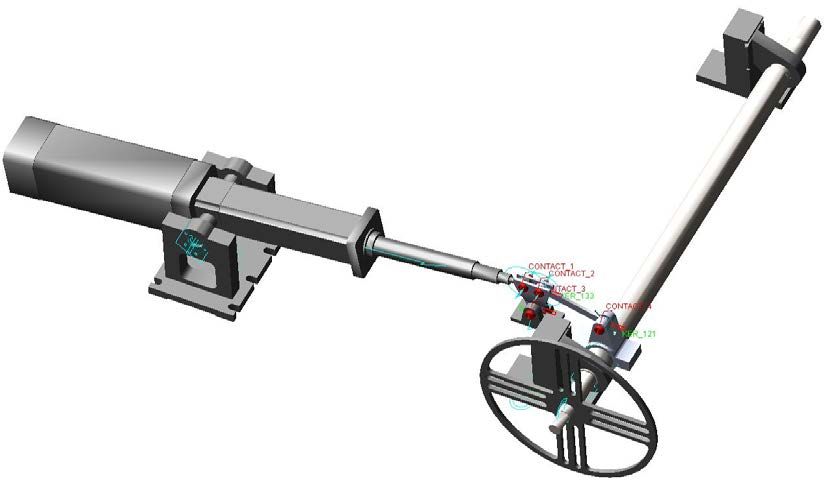
       bearing house 1       actuator           rod 1       lever arm 1         rod 2                    shaft                                 bearing house 4

                                                                                                                                               bearing house 2

                                                                                                                                                 lever arm 2
                                                                                    1     2

                                                                                                     4
                                                                                3                                                              bearing house 3

                                                                                                                                                 inertia plate

       Fig. 2. Dynamic model of flap actuation system with four clearance joints.

                                                                                3
MATEC Web of Conferences 306, 010 01 (2020)                                                                                                                                                        https://doi.org/10.1051/matecconf/202030601001
ICMME 2019

                                                  ×102                                                                                                                  ×102     ①                       ②                    ③           ④          ⑤
                                            1.8                                                                                                                     4            1         4 ×10
                                                                                                                                                                                                   2
                                                                                                                                                                                                                                   ×102

                                                                                                                                                                                                                        ①    0.2                       ④
                                            1.2                                                                                                                                  2
       Angular velocity (deg/s)

                                                                                                                                                                                           2                                 0.1
                                                                                                                                                                    3            3

                                                                                                          Contact force (N)
                                            0.6                                                                                                                                  4
                                                                                                                                                                                           0                                 0.0

                                                                                                                                                                                               0.0073     0.0074   0.0075    0.0112       0.0119   0.0126

                                            0.0                                                                                                                     2
                                                                                                                                                                                           ×102

                                                                                                                                                                                     0.2                               ②
                                    -0.6                                                                                                                                             0.1

                                                                                                                                                                    1                0.0

                                    -1.2                                          ideal                                                                                                0.0087            0.0090     0.0093

                                    -1.8                                          four clearances
                                                                                                                                                                    0
                                        0.0              0.1      0.2      0.3        0.4       0.5                                                                 0.006 0.007 0.008 0.009 0.010 0.011 0.012 0.013 0.014
                                                                    Time (s)                                                                                                              Time (s)
                                                           (a) Angular velocity                                                                                                                        (a) Contact force
                                                  ×104

                                                                                                           Angular acceleration (deg/s2) Angular velocity (deg/s)
                                                                                                                                                                    -1.46 ×10
                                                                                                                                                                                 2     ①                                                              ⑤
                                             2
                                                                                  ideal
             Angular acceleation (deg/s2)

                                                                                  four clearances
                                             1                                                                                                                      -1.47

                                             0                                                                                                                      -1.48

                                             -1                                                                                                                     -1.49
                                                                                                                                                                              ×104
                                                                                                                                                                        0.3
                                             -2
                                               0.0       0.1      0.2      0.3       0.4       0.5                                                                      0.2
                                                                    Time (s)
                          (b) Angular acceleration                                                                                                                      0.1
       Fig. 3. Dynamic responses of the system with four clearances.
                                                                                                                                                                        0.0
           Fig. 4 shows the dynamic responses of the system
       during the period time between 0.006 and 0.014 seconds.                                                                                                            0.006 0.007 0.008 0.009 0.010 0.011 0.012 0.013 0.014
       Contact forces at four clearance joints with five marked                                                                                                                                 Time (s)
       time indicate five combination mode, which are                                                                           (b) Angular velocity and angular acceleration of cases ①⑤
       presented as follows.                                                                                                                                              ×104                            ②                    ③          ④
                                                                                                                                                                    0.2
       Case ① Impact-impact-free-free combination mode
                                                                                                          Angular acceleation (deg/s2)

       Case ② Free-contact-contact-contact combination mode
                                                                                                                                                                    0.1
       Case ③ Free-contact-free-contact combination mode
       Case ④ Free-free-free-contact combination mode
                                                                                                                                                                    0.0
       Case ⑤ Contact-contact-free-impact combination mode
                                                                                                                                                                                                                                               four
       (1) Cases ①⑤                                                                                                                                                                                                                            one(1)
                                                                                                                                                          -0.1
           Case ① shows that there occurs an unexpected                                                                                                                                                                                        two(1,3)
       increase at the contact forces of the first and second                                                                                                                                                                                  three(1,2,3)
       joints, meaning that they are in impact motion, and the                                                                                            -0.2
                                                                                                                                                             0.006 0.007 0.008 0.009 0.010 0.011 0.012 0.013 0.014
       contact forces at the third and fourth joints are zero,
                                                                                                                                                                                   Time (s)
       indicating that the latter two joints are in free flight
       motion. As the fourth joint is connected with the lever                                                       (c) Angular acceleration of cases ②③④
                                                                                                          Fig. 4. Dynamic responses of the system at the beginning of
       arm2 and shaft of the system, the motion mode of the
                                                                                                          numerical simulation
       fourth joint can reflect the motion state of the flap
       actuation system. When the fourth joints is in the free                                            (2) Cases ②③④
       flight mode, there is no reaction force acted on the shaft,                                            Case ② shows that the first joint is in the free flight
       and hence, the angular acceleration of the system is                                               mode due to the null contact force and the latter three
       equalled to zero and its angular velocity keeps a constant                                         joints are in the continuous contact mode because of the
       value, as shown in the Fig. 4(b). Case ⑤ shows that the                                            stable contact forces. It can be observed from the Fig.
       angular acceleration of the system changes abruptly and                                            4(c) that the system angular acceleration curve almost
       the angular velocity keeps increasing, since the impact                                            coincides with that of only the first clearance joint
       force occurred in the fourth joint with the assumption                                             situation. Similar to case ②, it can be observed in case
       that the lever arm2 and shaft are modelled as two rigid
                                                                                                          ③. When contact motion occurs in the second and fourth
       parts.
                                                                                                          joints, the system angular acceleration curve almost
           Therefore, the change tendency of system responses
                                                                                                          overlap that of cases which only considers two clearance
       can judged by the motion mode of the joint connected
                                                                                                          joints including the first and third joints. Similarly, this
       with the output component.

                                                                                                      4
MATEC Web of Conferences 306, 010 01 (2020)                                                         https://doi.org/10.1051/matecconf/202030601001
ICMME 2019

       is evident in case ④, the system angular acceleration                    Acknowledgments
       curve with four clearance joints case almost coincides
       with the one with three clearance joints, namely the first,              This research was supported by the National Natural Science
       second and third one.                                                    Foundation of China (Grant No. 51675429), Key Project of
                                                                                National Natural Science Foundation of China (Grant No.
           Fig. 5 presents the contact forces of the four
                                                                                51535009), the Fundamental Research Funds for the Central
       clearance joints after the system reaches a steady state,                Universities (Grant No.31020190504003) and the 111 Project
       which appears that the clearance joint located closer to                 (Grant No. B13044). The authors would like to express their
       the input component undergoes the higher contact force                   appreciation to the agencies.
       and the corresponding conclusion can be obtained from
       the reference [6]. In addition, the second and fourth
       clearance joints, connected by a rigid rod, present almost               References
       the same contact force. The four clearance joints
                                                                                1.  D. Arriola, F. Thielecke, Model-based design and
       experience similar changing trends of contact force since
                                                                                    experimental verification of a monitoring concept
       impact mode occurred in one joint will immediately
                                                                                    for an active-active electromechanical aileron
       affect other joints in the rigid system.
                                                                                    actuation system. Mech Syst Signal Pr, 94, 322-345
                                ×102                                                (2017)
                           21
                                                                     1          2. Y. Y. Li, Z. L. Wang, C. Wang, W H Huang, Planar
                                                                     2              rigid-flexible coupling spacecraft modeling and
       Contact force (N)

                                                                     3              control considering solar array deployment and joint
                           14                                                       clearance. Acta Astronaut, 142, 138-151 (2018)
                                                                     4
                                                                                3. Z. F. Bai, J. J. Zhao, J. Chen, Y. Zhao, Design
                           7                                                        optimization of dual-axis driving mechanism for
                                                                                    satellite antenna with two planar revolute clearance
                                                                                    joints, Acta Astronaut, 144, 80-89 (2018)
                           0                                                    4. B. Li, S. M. Wang, V. Makis, X. Z. Xue, Dynamic
                           0.40        0.42   0.44     0.46   0.48   0.50           characteristics of planar linear array deployable
                                                 Time (s)                           structure based on scissor-like element with
       Fig. 5. Contact force of the four clearance joints at the end of             differently located revolute clearance joints, Proc
       numerical simulation                                                         IMechE Part C: J Mechanical Engineering Science,
                                                                                    232 (10), 1759-1777 (2018)
       4 Conclusions                                                            5. O. Muvengei, J. Kihiu, B. Ikua, Dynamic analysis of
                                                                                    planar rigid-body mechanical systems with two-
       In this paper, the dynamic characteristics of flap                           clearance revolute joints. Nonlinear Dynam, 73,
       actuation system with four clearance joints are                              259-273 (2013)
       investigated using computational methodology, where                      6. J. Ma, L. F. Qian, Modeling and simulation of
       the contact force model is described by the “Impact-                         planar multibody systems considering multiple
       function”, which consists of a nonlinear normal contact                      revolute clearance joints. Nonlinear Dynam, 90,
       force model and a modified Coulomb friction model.                           1907-1940 (2017)
       And then the influence of clearances on the system
       dynamic interaction phenomenon is further analysed and                   7. C. Birleanu, S. Talu, Machine elements. Designing
       some combination modes are illustrated.                                      and computer assisted graphical representations,
           From the numerical simulation results, it can be                         Cluj-Napoca, Romania, Victor Melenti Publishing
       concluded that the existence of joint clearances will lead                   house, 2001. ISBN 973-99539-6-4.
       to the worse dynamic behaviours of the flap actuation                    8. T. Nitulescu, S. Talu, Applications of descriptive
       system, namely, angular velocity, angular acceleration                       geometry and computer aided design in engineering
       and contact force. 1) There exists a strong dynamic                          graphics,     Cluj-Napoca,     Romania,    Risoprint
       interaction between four clearance joints, where the                         Publishing house, 2001. ISBN 973-656-102-X.
       impact mode occurred in one joint will immediately                       9. I. Khemili, L. Romdhane, Dynamic analysis of a
       affect other joints. 2) It is clear that the clearance joint                 flexible slider-crank mechanism with clearance. Eur
       nearer to the input component appears higher contact                         J Mech A-Solid, 27, 882-898 (2008)
       force and four joints present the similar trend of contact               10. Y. Chen, Y. Sun, C. Chen, Dynamic analysis of a
       force when the system reaches stable, particularly, the                      planar slider-crank mechanism with clearance for a
       contact forces of two joints connected by a rigid rod are                    high speed and heavy load press system. Mech
       almost the same. 3) The system stability can judged by                       Mach Theory, 98, 81-100 (2016)
       the motion mode of the joint connected with the output
       component. 4) When one joint is in the continuous                        11. MDI. Building models in ADAMS/View, 2012,
       contact motion mode, the angular acceleration of this                        ADAMS/Solver online help.
       system will coincide with that in the occasion of the joint
       is considered as ideal.

                                                                            5
You can also read