Comparison of BCF-10, BCF-12, and BCF-20 Scintillating Fibers for Use in a 1-Dimensional Linear Sensor
←
→
Page content transcription
If your browser does not render page correctly, please read the page content below
INL/CON-12-25807
                                                                   PREPRINT

Comparison of BCF-10,
BCF-12, and BCF-20
Scintillating Fibers for
Use in a 1-Dimensional
Linear Sensor

IEEE 2012 Nuclear Science Symposium
David L. Chichester
Scott M. Watson
James T. Johnson

October 2012

This is a preprint of a paper intended for publication in a journal or
proceedings. Since changes may be made before publication, this
preprint should not be cited or reproduced without permission of the
author. This document was prepared as an account of work
sponsored by an agency of the United States Government. Neither
the United States Government nor any agency thereof, or any of
their employees, makes any warranty, expressed or implied, or
assumes any legal liability or responsibility for any third party’s use,
or the results of such use, of any information, apparatus, product or
process disclosed in this report, or represents that its use by such
third party would not infringe privately owned rights. The views
expressed in this paper are not necessarily those of the United
States Government or the sponsoring agency.
INL-CON-12-25807
Comparison of BCF-10, BCF-12, and BCF-20
Scintillating Fibers for Use in a 1-Dimensional
Linear Sensor
David L. Chichester, Senior Member, IEEE, Scott M. Watson, and James T. Johnson
Abstract – One-dimensional fiber-bundle arrays may prove studies performed to assess the performance of three different
useful in a number of radiation sensing applications where candidate SFB materials.
radiation detection over large areas is needed. Tests have been
performed to evaluate the light generation and transmission II. BACKGROUND INFORMATION
characteristics of 15-meter long, 10-fiber bundles of BCF-10,
BCF-12, and BCF-20 scintillating fibers (Saint Gobain) exposed Early work using SFB assemblies for radiation detection
to collimated gamma-ray sources. The test set-up used one and measurement primarily dealt with using thousands of
R9800 (Hamamatsu) photomultiplier tube (PMT) at each end, short length (~10-cm long) scintillating fibers, such as NE-
with a high-speed waveform digitizer to collect data. Time 103, bundled together to create a single sensor unit, usually in
constraints were imposed on the waveform data to perform time- the form of a right cylinder using plastic fibers embedded in a
of-flight analysis of the events in the fiber bundles, eliminating plastic matrix.[1,2] This form factor, originally developed for
spurious noise pulses in the high gain PMTs and also allowing 1- space research, was found useful as a tool for providing a
dimensional localization of interactions along the lengths of the
fiber bundles. This paper will present the results of these
directionally sensitive neutron probe and was later expanded
measurements including the attenuation coefficients of the three and improved upon for terrestrial survey applications. Later,
fiber types and the timing resolution (position uncertainty) other researchers continued these efforts and subsequently
possible for each fiber bundle when using the R9800 PMTs. developed several other scintillating fiber detectors for
measuring neutrons in the same cylindrical form factor.[3-8]
Overtime detector developers eventually began to use boron-
I. INTRODUCTION or lithium-based fibers in some cases to increase the thermal
neutron sensitivity of their instruments.
Long, small-diameter scintillating fiber bundle (SFB)
assemblies are under investigation at Idaho National
As the technology needed to manufacture longer length
fiber optics was developed, interest in using longer length
Laboratory (INL) with the goal of developing one-
scintillating fibers as radiation instrumentation grew as well,
dimensional (1-D) linear sensors that may be used for
along two different paths. In one case researchers chose to
monitoring and characterizing ionizing radiation fields over
use newly available long-length fibers to create neutron and
long distances or over large areas. There are several needs for
gamma-ray detectors using ribbons, or "sheets" of fibers,
low-technology, distributed sensor networks that are capable
making flexible ribbon detectors or large-area detector
of monitoring radiation fields including radiation health
panels.[ 9,10] In one case, for example, over 250 km of ~2 m
physics, system monitoring at large facilities (nuclear reactors,
long glass fibers were used to create a 5 m2 sensor panel.[11]
nuclear material processing facilities, high-energy particle
Using scintillation fibers in large-area radiation
accelerators, hospitals, etc.), and nuclear security and
instrumentation found particular traction within the
nonproliferation applications. Traditional approaches involve
community of physicists developing instruments for high-
the emplacement of discrete instrumentation at closely-spaced
energy particle accelerator facilities.[12-14] They have also
intervals; continuous sensors have the ability to eliminate gaps
found application in health physics and homeland security
or weak-spots in between such sensors modules, while at the
applications.
same time reducing support infrastructure requirements
In the second implementation, radiation detector developers
including installed equipment mounting and power
sought to exploit the flexible, long-length scintillating fibers
consumption. This paper presents an overview of prior
in the form of line detectors. In some cases small-sized
research in this area and then presents the results of recent
detectors on the order of one cm in length were spliced
together with standard non-scintillating fibers and used as
point detectors. An application for these types of detectors is
Manuscript received November 11, 2012. Idaho National Laboratory is in the field of medical physics and radiation oncology, where
operated for the U.S. Department of Energy by Battelle Energy Alliance under thin diameter fibers are inserted into patients intravenously to
DOE contract DE-AC07-05-ID14517. measure the dose applied to patients during radiation
D. L. Chichester (telephone: 208-526-8920, e-mail:
david.chichester@inl.gov), S. M. Watson (telephone: 208-525-0572, e-mail:
therapy.[15-18] In contrast with the applications presented
scott.watson@inl.gov) and J. T. Johnson (telephone: 208-525-0572, above, here the goal was to measure photon radiation rather
email:james.johnson@inl.gov) are all with Idaho National Laboratory, Idaho than neutron radiation. In other cases long, thin fibers have
Falls, Id., 83415, USA. been used as area photon radiation monitors for health physics
The author's would like to acknowledge the support of Idaho National protection in accelerator beam halls and at nuclear
Laboratory's Laboratory–Directed Research and Development (LDRD)
program for this work. reactors.[19-23] In particular, recent research described byINL-CON-12-25807
Nohtomi et al. provides a valuable starting point for Fig. 1 A magnified photo of one end of the BFC-10 SFB, showing
orientation and optical polish. Note the air gap in the upper right due to epoxy
considering the use of SFB detectors for nuclear security and wicking up into the fiber bundle, this does not affect operation. For scale note
nonproliferation applications.[23] that the fibers are 1 mm in diameter.
III. EQUIPMENT AND METHODS The specially-made end fittings of the SFBs were designed
Four SFB assemblies, each comprised of ten individual to allow them to be easily attached or detached from a pair of
fibers, were assembled for this project using the commercial Hamamatsu R9800 photomultiplier tubes (PMTs) built as
scintillating fibers BCF-10, BCF-12, and BCF-20 (Saint Hamamatsu H10580 PMT assemblies with matching end
Gobain Crystals, Hiram, Ohio, USA).[24] The vendor- fixtures. Technical specifications for the R9800 PMT, as
supplied technical specifications for these materials are provided by the vendor, are provided in Table II. A
presented in Table I. BCF-10 fibers were used to make one comparison of the emission spectra for the three types of
2.2-m long SFB and one 14.85-m long SFB. BCF-12 and fibers, and the R9800 PMT quantum efficiency spectrum are
BCF-20 were used to make one SFB each; the BCF-12 SFB shown together in Fig. 2.[24,25]
was 15.18-m long and the BCF-20 SFB was 15.28-m long.
TABLE II IMPORTANT PARAMETERS FOR THE R9800 PMT.[25]
The fibers within each SFB were loosely bunched together
and packaged within a light-tight, flexible vinyl tubing. The
approximate outside diameters of these bundles is 0.5 cm. Parameter R9800 PMT
The ends of the SFBs were potted within a clear plastic matrix Rise time, ns 1.0
to create a larger diameter (1-cm) end fitting. The fibers were
polished by the vendor; an example of the end of one of the Transit time spread (full-width half 0.270
SFBs is shown in Fig. 1. As a test to determine if further maximum, FWHM), ns
polishing was needed, the ends of the 2.2-m fiber were Wavelength of maximum response, nm 420
finished with a graded-approach, hand-sanding technique
using 600-grit, 800-grit, and 1000-grit wet sand, and then a Gain 1.1 u 106
1200-grit diamond wheel. After this, the ends of the SFBs Photocatode material Bialkali
were hand polished using a felt polishing wheel with iron-
oxide slurry. Minimal improvement was observed. Window material Borosilicate glass
TABLE I IMPORTANT PARAMETERS FOR BCF-10, BCF-12, AND BCF-20.[24] Window effective diameter, cm 2.2
Parameter BCF-10 BCF-12 BCF-20 1.0
BCF-10
Emission spectrum;
Core material Polystyrene (common for all three) BCF-12
quantum efficiency
BCF-20
R9800 PMT
Core refractive index 1.60 (common for all three)
Density 1.05 (common for all three) 0.5
Emission peak, nm 432 435 492
Decay time, ns 2.7 3.2 2.7
*
1/e length, m 2.2 2.7 >3.5 0.0
300 400 500 600 700
# of photons per MeV** ~8000 ~8000 ~8000 Wavelength, nm
* For 1-mm diameter fiber; measured with a bialkali cathode Fig. 2 The emission spectra for BCF-10, BCF-12, and BCF-20, together
photomultiplier tube(PMT). with the energy-dependent quantum efficiency for the R9800 PMT.[24,25]
** For minimum ionizing particle (MIP), corrected for PMT sensitivity.
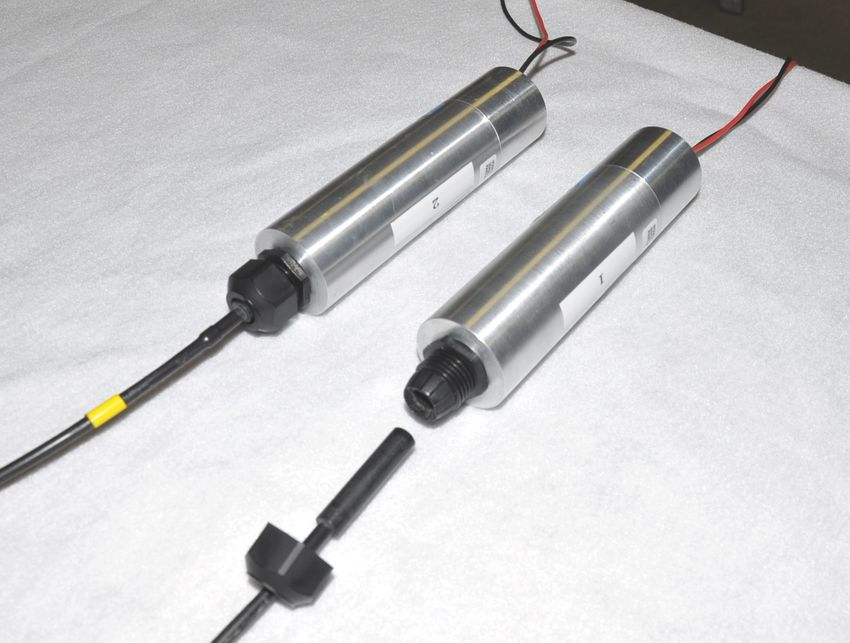
The PMTs are housed within light-tight aluminum cases;
these cases have threaded plastic fixtures in front of their
photocathodes to hold and stabilize the end of a SFB. To
attach the end of a SFB to the PMT module a plastic
compression fitting is placed over the end of the SFB, the SFB
is inserted into a hole on the PMT housing to position the SFB
in front of the PMT, and the compression fitting is screwed
tight onto a threaded fitting on the PMT housing. Each PMT
assembly includes a transparent optical silicone pad for index
matching between the SFB and PMT. A photograph of the
PMT assembly, showing attachment of an SFB, is presented in
Fig. 3.
Measurements were performed by digitizing the output
The BCF-10 SFB signals of the PMT’s using two channels of an AcquirisINL-CON-12-25807
DC282 high-speed digitizer (4Gs/s). The DC282 was attenuation versus path length) position linearity, position
controlled by National Instruments LabView software. An resolution, efficiency, and linearity versus rate. The following
application specific virtual instrument (VI) was developed subsections present the experimental results for tests studying
using LabView that allowed the difference in arrival time of these characteristics.
the signals between the two PMT’s to be recorded, triggering
A. Coincident Pulse Height Amplitude
off of either PMT. Slight timing errors occurred due to
latency between the hardware and software derived triggers A plot showing a pulse-height histogram for the Voltage
for each PMT input to the digitizer but these wereINL-CON-12-25807
digitizer and the LabView VI to pick-off signal times. factor of 8.5 cm ns-1 from Fig. 6. Overall the spatial
Scattering and reflection as the light transits down the length resolution across the 15-m long SFBs is between 50-60 cm.
of the SFB also plays a role.[26] The spatial resolution is slightly better towards the ends than
in the middle, most likely due to the reduced effect light
15000 scattering has on the signal reaching the nearer PMT versus
11.14 m Middle
BCF-10 the farther PMT (this can be seen in the plots of Fig. 5 where
4.73 m the time plots near the ends of the SFBs becomes more
10000 14.74 m asymmetric, with the inner edges of these distributions
Counts
looking more like 'pure' Gaussian distributions.) The absolute
5000
signal intensity from the BCF-10 SBF was significantly larger
0.11 m
than for the other two (next section.) This leads to a better
signal-to-noise characteristic for these SFBs, which is likely
0 the reason why the spatial resolution for BCF-10 is the best of
the three.
5000
BCF-12 TABLE III TEMPORAL AND SPATIAL RESOLUTION OF THE BCF-10, BCF-12,
4000 AND BCF-20 SCINTILLATING FIBER BUNDLES.[24]
Counts
3000 3.69 m
Resolving time (FWHM), ns (± 0.5 ns)
2000
SFB 0.11 m 3.82 m 7.64 m 11.46 m 15.17 m
1000
BCF-10 6.1 6.2 6.3 6.2 6.2
0
BCF-12 6.0 6.7 6.9 6.7 6.1
5000 BCF-20 6.2 7.5 7.8 7.5 6.6
BCF-20
4000 3.69 m Spatial resolution (FWHM), cm (± 4.2 cm)
Counts
3000 SFB 0.11 m 3.82 m 7.64 m 11.46 m 15.17 m
2000 BCF-10 51.7 52.6 53.4 52.6 52.6
1000 BCF-12 50.9 56.8 58.5 56.8 51.7
0 BCF-20 52.6 63.6 66.1 63.6 56.0
-100 0 100
Time, ns
Fig. 5 These three plots show the timing resolution for measuring events in
each SFB using a well-collimated 137Cs source. (Note: For the BCF-12 and D. Efficiency
BCF-20 SFBs, the second measurements taken from zero (nominal 4.73 m for
BCF-10, red trace) were taken at 3.69 m.)
The measurement efficiency for the three SFBs was
determined from the fifteen measurements of Fig. 5 using the
collimated 137Cs; this information is presented in Fig. 7. The
15 SFBs are most sensitive in their middles, where the signal-to-
BCF-10 noise characteristics in the PMTs are balanced. As the source
BCF-12 is moved towards the ends it becomes more likely that, for any
Position, m
10 BCF-20
particular event, the signal reaching the far PMT will either be
too noisy (failing the pulse-shape analysis in the LabView VI
algorithm) or too weak (falling below the trigger level of the
5 Y = -0.085 t + 7.425 count discriminator). As presented above, the BCF-10 SFB is
the most sensitive of the three tested, having a maximum
0 efficiency of 26.9 counts s-1 per mrem hr-1 (2.69 counts s-1 per
PSv hr-1.) The maximum efficiency for BCF-12 is 10.6 counts
-100 -50 0 50 100
s-1 per mrem hr-1 (1.06 counts s-1 per PSv hr-1.) The
Time, ns maximum efficiency for BCF-20 is 13.9 counts s-1 per mrem
Fig. 6 Plot showing the relationship between time and position for BCF-
10, BCF-12, and BCF-20.
hr-1 (1.39 counts s-1 per PSv hr-1.) The relative efficiency of
each SFB is also presented in Fig. 7. The trend of efficiency
versus position along the SFB is consistent among all three
C. Position Resolution sensors. It is worth noting here that the absolute efficiency
The spatial resolution for these measurements is evident as likely scales with the number of fibers in the SFB,
the full-width half-maximum of the time differences for the considerably more fibers could be included in a single SFB.
individual measurements seen in Fig. 5. This information is However, this scaling may not be linear. It is possible that the
presented in Table III. Additionally, these time difference total SFB efficiency may be more than the sum of the
values have been converted to distance, using the conversion efficiency per fiber as Compton-scattered electrons generatedINL-CON-12-25807
in one fiber (leading to a scintillation in that fiber) have a
chance to interact in nearby fibers as well. This relationship
awaits further study. 500
-1
Measured rate, counts s
300 30
BCF-10 400
-1
BCF-12
-1
Measured rate, counts s
250
counts s per mrem hr
BCF-20 300
200 20
Efficiency,
200
150 100
-1
60
Co
100 10 0
0 2 4 6 8 10 12 14
-1
50 Dose rate, mrem hr
Fig. 8 Test of the linearity of the BCF-10 SFB, measured at the center of
the SFB, for varying 137Cs dose rates from 1.2 mrem hr-1 to 14 mrem hr-1.
0 0
Also shown here is the BCF-10 SFB response to a 3.8 mrem hr-1 60Co source.
1.0
V. SUMMARY
SFB linear detector sensors can effectively detect low-level
0.8
Relative efficiency
gamma-ray radiation fields over long distances in a
continuous fashion. The response is exceptionally linear over
0.6 BCF-10 a range of >15 m and they exhibit a spatial resolution of 0.5 to
BCF-12 0.6 m, depending upon fiber type and position along the fiber.
0.4
BCF-20 Their efficiency has been measured to be from 3.3 counts s-1
per mrem hr-1 to 26.9 counts s-1 per mrem hr-1 (0.33 counts s-1
per PSv hr-1 to 2.69 counts s-1 per PSv hr-1) depending upon
0.2 fiber type and location along the SFB. BCF-10 is the most
efficient of the three fiber-types studied, while BCF-12 is the
0.0 least efficient. With the best spatial resolution as well, BCF-
0 5 10 15 10 appears to be the best candidate fiber, of the three studied,
Position, m for use in sensor arrays of length ~15m or less. However,
Fig. 7 The top plot shows the measured count rate, and the computed with the longest 1/e length, the BCF-20 fiber type may be a
efficiency, for the three SFBs measuring a 10 mrem hr-1 137Cs source. The better choice for longer length sensors. Further, the
lower plot shows the position-dependent relative efficiency, with each SFB performance from a BCF-20 SFB could likely be improved by
normalized to its maximum count rate.
choosing a different PMT with a spectral response more
closely matched to the longer-wavelength output spectrum of
E. Linearity Versus Rate this fiber.
A separate test was performed to examine the linearity in Further work is needed to improve the data acquisition
response for BCF-10 versus dose rate. This test used the 137Cs electronics used for this work, in particular to lower the signal
check source. The test started by resting the center of the SFB noise and improve the signal-to-noise relationships and allow
against the check source to achieve the maximum dose rate, lowering of the lower level discrimination in the trigger logic.
14 mrem hr-1 (1.4 mSv hr-1.) Tungsten plates were then Further work is also justified for studying, with improved data
placed around the check source to separate the distance acquisition, the limits for how long a SFB is practical for these
between the source and SFB – decreasing the dose rate at the measurements. Lastly, it should be noted that the efficiency
SFB. The maximum stand-off depth for the check source of the SFB-type sensors used here can be easily improved by
from the SFB was 6.7 cm, producing a dose rate of 1.2 mrem including more fibers in the SFB assemblies.
hr-1 (0.12 mSv hr-1.) Measurements were made at seven
different positions; the results are shown in Fig. 8. An VI. ACKNOWLEDGEMENTS
acceptable (R2 = 0.9965) linear fit has been applied to the < 7 We would like to acknowledge and thank Mr. Michael
mrem hr-1 data in the plot. However, it appears that for the Mayhugh of Saint-Gobain Crystals for his assistance
bare case, and the case with minimal collimation (7 mm, 10 preparing the SFB assemblies used in this project and for
mrem hr-1 (0.10 mSv hr-1,) a greater section of the SFB was providing assistance with the concept and testing. We would
exposed to the source (e.g., this collimation was not effective also like to acknowledge and thank Prof. Akihiro Nohtomi of
in exposing a uniform section of SFB). In this non-ideal case, Kinki University, Japan, for his thoughtful suggestions and
however, the BCF-10 SFB appears to provide a conservative guidance early on in this project.
estimate of dose field in terms of radiological health
protection. A measurement made using the 60Co source is also REFERENCES
presented on this plot.INL-CON-12-25807
[1] Reynolds, G. T. and Condon, P. E., "Filament Scintillation Counter,"
Rev. Sci. Inst. 28 (1957) 1098-1099.
[2] Chupp, E. L. and Forrest, D. J., "A Directional Neutron Detector for
Space research Use," IEEE Trans. Nucl. Sci. 13 (1966) 468-477.
[3] Atkinson, M., et al., "Initial Tests of a High Resolution Scintillating
Fibre (SCIFI) Tracker," Nucl. Inst. Meth. Phys. Res. A 254 (1987) 500-
514.
[4] Wurden, G. A., et al., "A Scintillating-Fiber 14-MeV Neutron Detector
on TFTR During DT Operation," Report LA-UR-94-1604, Los Alamos
National Laboratory, Los Alamos, N. M. (1994).
[5] Holslin, D., et al., "A Directional Fast Neutron Detector Using
Scintillating Fibers and an Intensified CCD Camera System," Nucl. Inst.
Meth. Phys. Res. A 353 (1994) 118-122.
[6] Sailor, W. C., et al., "Conceptual Design for a Scintillating-Fiber
Neutron Detector for Fusion reactor Plasma Diagnostics," Rev. Sci. Inst.
66 (1995) 898-900.
[7] Ress, D., et al., "High-Sensitivity Scintillating-Fiber Imaging Detector
for High-Energy Neutrons," Rev. Sci. Inst. 66 (1995) 4943-4948.
[8] Zhang, Q., Wang, Q., and Xie, Z., "Detection of Fast Neutrons Using a
New Scintillating-Fiber-Array Neutron Detector," Nucl. Inst. Meth.
Phys. Res. A 496 (2003) 228-232.
[9] Grazioso, R. F., et al., "Feasibility of Using Boron-Loaded Plastic Fibers
for Neutron Detection," Nucl. Inst. Meth. Phys. Res. A 422 (1999) 59-
63.
[10] Yamashita, M., Nozaki, T., and Ninomiya, K., "Development of a Sheet
Type Contamination Monitor Using the Plastic Scintillation Fiber
(PSF)," Proc. 10th Congress Int. Rad. Prot. Assoc., Hiroshima, Japan,
May 14-19 (2000).
[11] Abel, K. H., et al., "Scintillating-Glass-Fiber Neutron Sensors," Nucl.
Inst. Meth. Phys. Res. A 353 (1994) 114-117.
[12] Ruchti, R., et al., "Development of New Scintillating Fiber Detectors for
High Energy Physics Applications," IEEE Trans. Nucl. Sci 36 (1989)
146-149.
[13] Angelini, C. et al., "High-Resolution Tracking with Scintillating Fibers,"
Nucl. Inst. Meth. Phys. Res. A 277 (1989) 132-137.
[14] D'Ambrosio, C., et al., "Particle Tracking with Scintillating Fibers,"
IEEE Trans. Nucl. Sci. 43 (1996) 2115-2127.
[15] Koechner, W., "Radiation Sensitive Optical Fiber and Detector," U.S.
Patent 4,788,436, November 29 (1988).
[16] Beddar, A. S., Mackie, T. R., and Attix, F. H., "Cerenkov Light
Generated in Optical Fibers and Other Light Pipes Irradiated by Electron
Beams," Phys. Med. Biol. 37 (1992) 925-935.
[17] Fluhs, D., et al., "Direct Reading Measurement of Absorbed Dose with
Plastic Scintillators – The General Concept and Applications to
Ophthalmic Plaque Dosimetry," Med. Phys. 23 (1996) 427-434.
[18] Beddar, A. S., et al., "A Miniature "Scintillator-Fiberoptic-PMT Detector
System for the Dosimetry of Small Fields in Stereotactic Radiosurgery,"
IEEE Trans. Nucl. Sci. 48 (2001) 924-928.
[19] Imai, S.-I., et al., "New Radiation Detector of Plastic Scintillating Fiber,"
Rev. Sci. Inst. 62 (1991) 1093-1097.
[20] Takada, E., et al., "Neutron Radiation Distribution Sensor Using
Flexible Plastic Scintillating Fiber Combined with the Time-of-Flight
Technique," IEEE Trans. Nucl . Sci. 42 (1995) 570-574.
[21] Oka, T., et al., "Development of Fiber Optic Radiation Monitor Using
Plastic Scintillation Fibers," J. Nucl. Sci. Tech. 35 (1998) 857-864.
[22] Makowski, D., et al., "A Distributed System for Radiation Monitoring at
Linear Accelerators," IEEE Trans. Nucl. Sci. 53 (2006) 2008-2015.
[23] Nohtomi, A., et al., "On-Line Evaluation of Spatial Dose-Distribution by
Using a 15m-Long Plastic Scintillation-Fiber Detector," IEEE Nucl. Sci.
Symp. Conf. Rec. (2008) 965-968.
[24] "Scintillating Products, Scintillating Optical Fibers," Product Brochure,
Saint Gobain Crystals, Hiram, Ohio, USA (www.detectors.saint-
gobain.com).
[25] "Photomultiplier Tube R9800," Product Brochure TPMH1298E04,
Hamamatsu Photonics, Iwata City, Shizuoka Prefecture, Japan (2010).
[26] Zugec, P., "A Timing Resolution Model for Scintillating Fibers," IEEE
Nucl. Sci. Symp. Conf. Rec. (2011) 1605-1608.You can also read