Bearing capacity assessment of bored piles equipped with expander body systems using the mechanics of unsaturated soils
←
→
Page content transcription
If your browser does not render page correctly, please read the page content below
MATEC Web of Conferences 337, 03011 (2021)                                                            https://doi.org/10.1051/matecconf/202133703011
PanAm-UNSAT 2021

             Bearing capacity assessment of bored piles equipped with
             expander body systems using the mechanics of unsaturated
             soils
             Fernando Feitosa Monteiro1,*, Renato Pinto da Cunha1, Marcos Fábio Porto de Aguiar2 and Carlos Medeiros Silva3
             1 University   of Brasília, Civil and Environmental Engineering Department, Brasília, Brazil.
             2   Federal Institute of Education, Science and Technology of Ceará, Civil Construction Department, Fortaleza, Brazil.
             3   EMBRE, Brasília, Brazil.

                            Abstract. Bearing capacity of single piles are occasionally predicted using the renowned theoretical
                            methods ( and  methods). These methods are based on laboratory tests, which can be time-
                            consuming, but also applicable in foundation engineering practice for unsaturated soils. Full-scale
                            pile load tests were carried out on bored piles equipped with Expander Body Systems in the Federal
                            District of Brazil, known for its unsaturated, collapsible and porous soil. This paper has the aim to
                            assess the applicability of the  method, considering the contribution of soil matric suction, in order
                            to estimate the bearing capacity of these piles subjected to uplift and compression loads in unsaturated
                            soils. Based on the experimental results, it is indicated that the use of the  method considering the
                            matric suction, can be a useful tool for bearing capacity estimation of bored piles equipped with
                            Expander Body Systems in unsaturated soils.

       1 Introduction
                                                                               This paper has the aim to assess the applicability of the
       Single piles bearing capacity is usually computed using                 method, considering the contribution of soil matric
       semi-empirical methods; however, renowned theoretical                   suction, in order to estimate the bearing capacity of bored
       methods ( and  methods) have also been employed in                    cast-in-situ piles equipped with the EB technology
       pile foundation engineering for many years [1]. Pile                    subjected to uplift and compression loads in lateritic,
       foundation behavior can be influenced by several aspects,               porous and unsaturated soil.
       such as soil shear strength parameters, soil saturation
       degree, soil compressibility, soil stress history and age, as
       well as pile installation technique. Many pile foundations              2 Bearing Capacity of Single Piles using
       are located above the groundwater table zone. Therefore,                the β Method
       soil-pile interaction can also be influenced by matric
       suction in these unsaturated soils. Also, the development               Pile foundation design has been commonly performed
       of novel pile installation methodologies subsidized                     based on saturated soil mechanics. However, a significant
       growing appeals for analyzing the applicability of                      amount of attention can be attributed to pile foundation
       theoretical bearing capacity methods. The Expander Body                 design for engineering fundamentals, in which the
       System is an innovative technology that can be attached                 mechanics of partly saturated soils have been widely
       to the toe of bored and driven piles. This system has been              applied [3-5].
       widely adopted as a pile foundation solution in prominent
       urban centers such as Santa Cruz de la Sierra, Bolivia [2].
                                                                               The following equation gives the ultimate pile bearing
       In Bolivia, more than 3000 pile foundation elements                     capacity:
       equipped with Expander Body technology have already
       been installed in 35 different engineering projects such as              =  +                                                  (1)
       bulk silos, industrial facilities, residential buildings and
       bridges. Many other countries, such as Sweden, Norway,
       Germany, Japan, Paraguay, Peru United States of
       America, South Korea and now Brazil, have implemented
       this building technology as a viable pile foundation
       solution.

             *
                 Corresponding author: engffmonteiro@gmail.com

  © The Authors, published by EDP Sciences. This is an open access article distributed under the terms of the Creative Commons Attribution License 4.0
  (http://creativecommons.org/licenses/by/4.0/).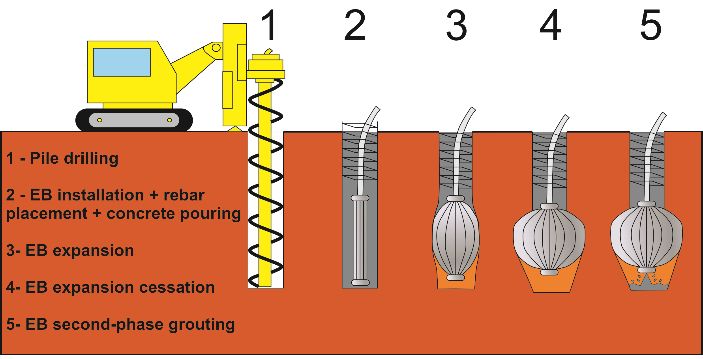
MATEC Web of Conferences 337, 03011 (2021) https://doi.org/10.1051/matecconf/202133703011
PanAm-UNSAT 2021
The conventional β method [6-7] establishes that skin 0.4 to 0.8 m. During EB expansion stage, the relationship
friction resistance (QS) and toe resistance (QT) can be between injection pressure and volume can be registered
given: by a data acquisition system. The lateral expansion of the
EB induces an EB tube length shortening by almost
0.2 m, displayed as a rising of the EB bottom-tip. This
= ∫ ∙ ( + ′ ) (2) expansion causes a soil decompression beneath the EB,
which is compensated by a second grouting stage of the
= ∙ ′ ∙ (3) soil at the pile tip (Figure 2). The second grouting stage is
discharged to the pile tip over a distinct grout tube inside
the grout tube (Figure 3) employed for the initial grouting
where: QT is the toe resistance, QS is the skin friction stage (passing the EB inner section).
resistance, c’ is the effective soil cohesion, is the
Bjerrum-Burland coefficient, Nt is the toe bearing
capacity coefficient, ’vp is the effective overburden stress
at the pile toe, ’z is the effective overburden stress, AT is
the pile toe area, PS is the pile shaft perimeter at depth z.
The Machado e Vilar (1998) [8] proposal was adopted in
order to evaluate the matric suction contribution on soil
cohesion, which directly influences pile skin friction
resistance. This proposal adjusts the cohesion variation
and matric suction by hyperbolic functions using the least-
squares method.
( )
= + (4)
∙( )
Fig. 2. Post-grouting stage after EB expansion.
where: c’ is the effective soil cohesion obtained in CU
triaxial and direct shear tests, (ua-uw) is the matric suction,
c is the apparent cohesion given a matric suction value, a
and b are adjustment coefficients. In this research, a and b
values of 3.725 and 0.012 were considered (as reported in
[9]), respectively.
3 The Expander Body System
The Expander Body System (EB) is a bent steel tube,
which is inflated (expanded) by an initial pressure-
grouting process, discharged discharged via a grouting
tube that goes down through the re-bar cage. Distinct Fig. 3. Grout tube passing the EB inner section.
models allow an expansion from 0.4 to 0.8 m in diameter.
Grout pressure and volume are registered continuously
during the expansion of the EB. Figure 1 depicts the EB 4 Materials and Methods
expansion stages during the pressure grouting step.
4.1 Pile installation
Diverse methods can be employed to build bored cast-in-
situ piles. The principle is essentially the same; there is,
however, a slight variation between these approaches. Pile
Fig. 1. Expander Body Expansion Stages. drilling excavation is usually performed utilizing a
percussive or rotary method with the use of permanent or
The Expander Body (EB) system is commercially temporary casing or drilling mud. Once design depth is
available in different dimensions depending on design reached, the drilling process is ceased. The reinforcement
requirements. The EB models have lengths between 1 and cage is placed, and the borehole is then filled with
2 m, as well as widths between 0.10 and 0.13 m in the concrete. The installation procedure of bored cast-in-situ
stages before the expansion (initial stage). The models piles equipped with Expander Body technology follows a
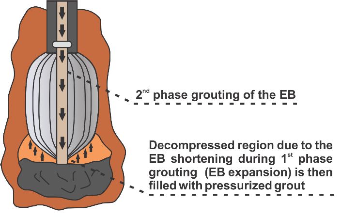
allow expansion, obtaining effective diameters between similar approach. Figure 4 depicts the installation
procedure of bored cast-in-situ pile equipped with the
2MATEC Web of Conferences 337, 03011 (2021) https://doi.org/10.1051/matecconf/202133703011
PanAm-UNSAT 2021
Expander Body system. The Expander Body's pre-loading Figure 5 depicts a simplified soil stratigraphy, average
effect specifically decreases required deformations to SPT blow counts, cone tip resistance and sleeve friction,
mobilize toe resistance when compared to traditional as well as soil parameters obtained in laboratory tests. The
bored piles. simplified geotechnical-geological soil profile is
characterized by a superficial laterite (silty sand) layer
that overtops a transition zone (clayey silt) and a saprolite
soil (sandy silt) that originates from the region native
rock. In situ tests were carried out to a depth of 18 m,
although, the water table level was not reached. Triaxial
tests on undisturbed block samples were performed at
depths of 3, 6, and 9 m. Initial tangent modulus (E i),
secant modulus at 50% of the failure stress (E50), soil
effective cohesion and friction angle were acquired
performing triaxial CD tests at cell pressures of 50, 100,
and 200 kPa on each depth. The lateritic soil was
classified as silty sand (SM), while the residual soil was
Fig. 4. Bored cast-in-situ piles equipped with EB system identified as low plasticity silt (ML) according to USCS.
installation procedure.
The installation procedure of bored piles equipped with
EB technology can be divided into five steps (Figure 4).
Initially, pile drilling is carried out. Secondly, the EB is
placed at design depth along with the reinforcement bars,
and then, concrete is poured into the borehole. The next
step consists of an initial grout phase, delivered through a
hollow schedule tube (EB expansion), as described in
Figure 4. After EB expansion ceases, the second-phase
grout step is carried out, so that the decompressed region
(pile tip) is filled with pressurized grout. Both injection
pressure and volume are continuously monitored using
Fig. 5. Soil stratigraphy and average parameters.
mortar pump and pressure gauge. These equipments not
only provide adequate monitoring of the EB expansion,
but also provides pressure-volume charts. 4.3 Pile load test
Test pile drilling excavation was performed with a
rotating hollow flight auger at the UnB research site. Once
4.2 Soil stratigraphy design depth was attained, the drilling process was ended,
and the reinforcement cage was placed. Subsequently, the
The Federal District is limited in the south by the parallel
EB was placed at design depth alongside 3 m length pile
16 ° 03 'and in the north by the parallel 15 ° 30', presenting
rebar, and then, the borehole was filled with concrete.
a total area of 5814 km2. The University of Brasília (UnB)
Thereafter, an initial grout phase was delivered through a
campus is situated within Brazil's Federal District, in an
hollow schedule tube attached to the EB (EB expansion).
area most widely recognized as the "north wing" due to its
Lastly, a second-phase grout step was carried out using a
aircraft shape. UnB geotechnical group research site has
high-pressure flexible hose that passes inside the EB to
already been intensively investigated and presented in
the pile toe. In addition, both injection volume and
literature [10]. The soil stratigraphy varies between clay,
pressure were continually monitored using mortar pump
silt, and silty sand in the upper portion of this region. For
and pressure gauge. These instruments not only provide
instance, occurrence of large areas (more than 80% of the
appropriate monitoring of EB expansion but also provide
Federal District area) covered by a tertiary-quaternary age
pressure versus volume records. The reinforcement cage
weathered laterite is typical. This lateritic soil has
consisted of primary CA-50 steel longitudinal rebars
undergone extensive leaching and presents a variable
(rebar = 16 mm) and transverse CA-50 steel spiral
thickness ranging from a few centimeters to about 40
stirrups rebars (rebar = 6.3 mm). The test piles were
meters. The high porosity produced by aggregation and
installed using 20 MPa concrete and 210 MPa steel
cementation resulting from processes such as leaching,
reinforcement. A water/cement ratio between 0.4 and 0.5
hydrolysis and cementitious agents deposition is observed
was employed during the primary and secondary grout
in many weathered tropical soils in Brazil. As a
injection phase. In piles subjected to uplift load tests, only
consequence, both soil void ratio and porosity are high. In
the main grout injection phase (EB expansion) was
situ standard penetration tests (SPT) and cone penetration
performed. Bored cast-in-situ reaction piles were installed
tests (CPT), as well as, usual characterization laboratory
with 0.3 m in diameter and 12 m long, with 47 mm
tests were conducted to evaluate main parameters of the
Dywidag reaction anchors of 14.5 m.
lateritic, unsaturated and collapsible soil site.
3MATEC Web of Conferences 337, 03011 (2021) https://doi.org/10.1051/matecconf/202133703011
PanAm-UNSAT 2021
Four static load tests were carried out using a reaction The compression load tests set-up displayed an H-shaped
system composed of reaction piles, reaction frame and reaction system, using two 3.2 m long secondary reaction
reaction frame support. Both compression and uplift frames and a 6 m long main reaction beam (Figure 8).
reaction systems set-up are displayed in Figures 6 and 7. While uplift load tests reaction system scheme was
The required duration to stabilize the displacements was composed with an H-shaped reaction system, consisting
spent after each axial load increment. In compliance with of a 3.6 m long main reaction frame and two concrete
the Brazilian Standard NBR 12131 [11], all intervals were reaction frame supports that were placed on the ground
maintained for at least 30 minutes until the Brazilian level (Figure 9). Load measurements at pile top were
standard criterion was accomplished. A 3.1 m center-to- conducted with a 2000 kN load cell, while displacement
center distance between the test pile and reaction piles measurement were performed using 50 mm dial gauges.
was adopted. Table 1 presents geometric characteristics of the test piles,
as well as test pile load type.
Fig. 8. Top view of compression pile load test set-up.
Fig. 6. End view of compression pile load test set-up.
Fig. 9. Top view of uplift pile load test set-up.
Table 1. Pile geometric characteristics and load type.
Test Pile (m) m L (m) Load Type
EBC-8.8 0.30 0.6 8.8 Compression
EBC-10 0.30 0.6 10.0 Compression
EBU-10 0.25 0.6 10.0 Uplift
EBU-8 0.25 0.6 8.0 Uplift
Note: EBC = Bored pile with Expander Body System
subjected to compression load; EBU = Bored pile with
Expander Body System subjected to uplift load; = pile
diameter; EB is the EB effective diameter after
expansion.
All load tests attended the slow maintained test procedure
(ABNT, 2006) [11] with load increments ranging from
approximately 55 and 120 kN. A summary of load test
Fig. 7. End view of uplift pile load test set-up. increments and pile ultimate load values of all tested piles
4MATEC Web of Conferences 337, 03011 (2021) https://doi.org/10.1051/matecconf/202133703011
PanAm-UNSAT 2021
is presented in Table 2. Load versus pile head
displacement curves are presented in Figure 10.
Table 2. Summary of test piles load and displacement data.
Load
Displacemet Pult
Test Pile (m) m increment
criterion (kN)
(kN)
EBC-8.8 0.30 0.6 10% 100 820
EBC-10 0.30 0.6 10% 120 1120
EBU-10 0.25 0.6 10% 98 880
EBU-8 0.25 0.6 10% 63 580
Fig. 12. Soil moisture content and saturation degree for different
depths.
5 Results and discussions
In this research, both toe and skin friction capacity of in-situ
single piles equipped with the Expander Body System were
predicted using the conventional β method, the β method
considering matric suction contribution and the conventional β
method considering Nt and β values proposed by Fellenius, 2020
[13]. The toe bearing capacity estimates for piles subjected to
uplift load was neglected; therefore, the bearing capacity of piles
Fig. 10. Pile load-displacement curves. subjected to uplift load was considered to be equal to pile shaft
resistance. The pile bearing capacity estimates were computed
by dividing the pile length into ΔL segments. β values were
4.4 In-situ and Laboratory tests computed using Poulos, 1989 [14] recommendation, as
described in the following equation for analyses using the
The soil-water characteristic curve (SWCC) was conventional β method and the β method considering matric
determined using the filter paper method on undisturbed suction contribution.
samples retrieved at depths ranging from 1 to 10 m
(Figure 11). Several moisture measures were carried out = (1 − sin
′) ∙ tan
′ ∙ ( !").# (5)
during in-situ tests performance. Soil matric suction was
then determined using both soil-water characteristic curve
and soil saturation degree along the pile length. Moisture where: ’ is the effective soil internal friction angle and
measures (Figure 12), as well as soil characterization tests OCR is the over-consolidation ratio.
(moisture content, Atterberg limits, specific gravity of soil
and dry density of soil) results, were used in order to The corresponding matric suction (ua-uw), for each
obtain soil saturation degree at each meter depth. saturation degree value along pile length, is determined
from the respective soil-water characteristic curve
(SWCC). Predicted (Qp) and measured (Qm) pile bearing
capacity ratios for each employed method are depicted in
Figures 13, 14, 15 and 16. For piles under compression
loads, a possible shaft resistance descrease immediately
above the enlarged EB was neglected. As for piles under
uplift loads, a potential pile skin friction increase was
disregarded. The Expander Body system is expanded after
pile installation, applying radial stresses along pile tip and
immediately above the enlarged part. This expansion
might lead to different stress-strain soil conditions from
conventional enlarged base piles, where this effect has
been previously analyzed. Moreover, Fellenius et al. 2018
[15] verified that equipping the pile toe with the EB with
Fig. 11. Soil-water characteristic curves at the UnB post-installation grouting considerably increased the pile
geotechnical group research site ([12] – modified). stiffness response to applied load. Therefore, the pile shaft
increase or decrease mechanism due to EB expansion is
yet undetermined.
5MATEC Web of Conferences 337, 03011 (2021) https://doi.org/10.1051/matecconf/202133703011
PanAm-UNSAT 2021
ratio, the piles under compression and uplift loads
presented a similar behavior for all analyzed methods.
Despite the limited data, it can be recommended that the
total pile bearing capacity should be reduced by nearly
33% for piles under compression when predicting the
bearing capacity of bored cast-in-situ piles equipped with
the Expander Body System using either the conventional
β method or the β method considering matric suction.
Fig. 13. Pile bearing capacity ratios – EBC – 8.8. While for piles subjected to uplift loads, an increase of
approximately 40% is suggested.
6 Conclusions
The main objective of this research was to assess the
applicability of the method, considering the contribution
of soil matric suction, in order to estimate the bearing
capacity of bored cast-in-situ piles equipped with the EB
Fig. 14. Pile bearing capacity ratios – EBC – 10. technology subjected to uplift and compression loads in
lateritic, porous and unsaturated soil. This article
emphasized four full-scale maintained static load test on
bored cast-in-situ piles equipped with EB system at the
UnB (University of Brasília) foundation research site.
This paper provides a comparison between the estimated
total pile bearing capacities of bored cast-in-situ piles
equipped with EB system using both the conventional
method and the method considering suction. The matric
Fig. 15. Pile bearing capacity ratios – EBU – 10. suction influence on the skin friction capacity of a single
pile was estimated by using the Machado e Vilar (1998)
[8] proposal, in order to assess the cohesion component
increase.
The findings show that matric suction has a slight
influence on the bearing capacity of bored cast-in-situ
piles equipped with EB system since its behavior is
mostly governed by pile toe resistance when analyzing
piles under compression loads. For piles subjected to
Fig. 16. Pile bearing capacity ratios – EBU – 8. uplift loads, matric suction influence increases, and pile
toe resistance should be neglected for practical purposes.
The method considering matric suction yields slightly Based on the experimental results, it is indicated that the
better bearing capacity estimates for piles subjected to use of the method considering the matric suction, can be
uplift loads, when compared to the conventional a useful tool for bearing capacity estimation of bored piles
method. On the other hand, conventional method equipped with Expander Body Systems in unsaturated
presented better estimates when analyzing piles under soils.
compression, however, all methods overestimated pile
bearing capacity. These findings can be attributed to the Full-scale pile load testing analysis often raises
fact that for compression piles, the toe bearing capacity limitations associated with sample size, making it difficult
has been considered, when estimating the total pile to identify meaningful relationships from analyzed data,
bearing capacity, in contrast, piles under uplift loads because statistical analyses usually require a larger
showed an opposite trend, underestimating pile bearing sample size to ensure a representative population
capacity, since only pile shaft resistance was taken in distribution. Hence, the need for future research on this
consideration. Consequently, it can be speculated that pile innovative building technology in typical tropical,
tip resistance is overestimated, while, pile skin friction unsaturated and lateritic soils of substantial occurrence in
resistance is underestimated when analyzing all examined Brazil should be emphasized.
methods in this research.
The skin friction resistance estimated by using the β Acknowledgements
method considering matric suction is approximately 10% This research was conducted under the tutelage of the
higher in comparison to the conventional β method for Foundation and Field Test Group (GPFees) of the University of
piles under compression, while in piles subjected to uplift Brasilia Geotechnical Post Graduate Program. The first author
loads, shaft capacity prediction is nearly 40% higher as would like to show his appreciation for the field assistance to the
well. Despite different embedment depths and slenderness engineering contractor EMBRE and the scholarship granted
6MATEC Web of Conferences 337, 03011 (2021) https://doi.org/10.1051/matecconf/202133703011
PanAm-UNSAT 2021
(GM/GD-140423/2017-6) by the governmental sponsorship 13. B. H. Fellenius. (2020). Basics of Foundation
organization CNPq (National Council for Scientifc and Design. Electronic Edition, www.Fellenius.net,
Technological Development). 527 p.
References 14. H. G. Poulos. (1989). Pile behaviour—theory and
application. Géotechnique. 39:3, 365-415, doi:
1. R. P. Cunha & P. J. R. Albuquerque. (2014). 10.1680/geot.1989.39.3.365
Advance of Foundation Techniques in Brazil Since 15. B. H. Fellenius, K. R. Massarsch, M. H. Terceros.
Colonial Times. DYNA (MEDELLÍN). 81, 178-187, (2018). A study of the augmenting effect of
doi: 10.15446/dyna.v81n183.31435. equipping piles with an Expander Body. DFI-EFFC
2. H. M. Terceros & K. M. Massarsch. (2014). The use International Conference on Deep Foundations and
of the expander body with cast in-situ piles in sandy Ground Improvement 1, 6-8, Rome.
soils. 11th International Conference on Piling and
Deep Foundations, 347-358, Stockholm.
3. D K. Georgiadis, D. M. Potts, & L. Zdravković.
(2003). The influence of partial soil saturation on pile
behavior. Géotechnique. 53:1, 11-25,
doi: 10.1680/geot.2003.53.1.1.1
4. N. Ravichandran, S. H. Krishnapillai & B. Machmer.
(2013). A novel procedure for physical modeling of
unsaturated soil-pile system using geotechnical
centrifuge. J. Earth Sci. Geotech. Eng. 3:1, 119-134.
5. Z. N. Taylan & S. K. Vanapalli. (2012) Estimation of
the Shaft Capacity of Single Piles Using the
Conventional and Modified β Method. Mancuso C.,
Jommi C., D’Onza F. (eds) Unsaturated Soils:
Research and Applications. Springer, Berlin,
Heidelberg. doi: 10.1007/978-3-642-31343-1_32
6. J. B. Burland. (1973). Shaft friction of piles in clay -
a simple fundamental approach. Ground Engineering.
6:3, 30–42.
7. R. J. Chandler. (1968). The shaft friction of piles in
cohesive soils in terms of effective stress. Civil
Engineering and Public Works Review. 48–51.
8. S. L. Machado & O. M. Vilar. (1998). Soil shear
strength: laboratory tests and expeditious
determination (In Portuguese). Solos e Rochas. 21:2,
65-78.
9. N. M. B. Mota. (2003). Advanced in situ Tests in the
Brasília Unsaturated Porous Clay: Interpretation
and Foundation Design Application (In Portuguese).
Ph.D Thesis. Civil and Environmental Engineering
Department, Brasília University, Brasília, Pub.
G.TD-013A/03, 336p.
10. R. P. Cunha. (2011). Acquired Knowledge on the
Behavior of Deep Foundations Vertically and
Horizontally Loaded in the Soil of Brasília. Soils and
Rocks. 34:3, 177-194.
11. ABNT. (2006). NBR12131: Piles – Static Load Test
– Test Method (In Portuguese). ABNT Brazilian
Association of Technical Standards, 8 p.
12. R. C. Guimarães. (2002). Analysis of the Properties
and Behavior of a Lateritic Soil Profile Applied to the
Study of Bored Piles Performance (In Portuguese).
MS.c. Dissertation, Civil and Environmental
Engineering Department, Brasília University,
Brasília, Pub. G.DM – 091A/02, 183 p.
7You can also read