DESIGN ANALYSIS AND FABRICATION OF THREE WHEEL SEGWAY - Mukt ...
←
→
Page content transcription
If your browser does not render page correctly, please read the page content below
Mukt Shabd Journal                                                                              ISSN NO : 2347-3150

                 DESIGN ANALYSIS AND FABRICATION OF THREE
                              WHEEL SEGWAY
                     B.S. Lakshmi Prasad *, R. Lovaraju,R. Saikoti, G.N.V.P.Kumar,
                                        K.Saikumar, G.Rahul.
                  *Asst.Professor, Anil Neerukonda Institute of Technology & Sciences,
                                   Visakhapatnam- 531162, A.P., India
                     B.Tech, Anil Neerukonda Institute of Technology & Sciences,
                                   Visakhapatnam-531162, A.P., India

            Abstract
                     In the present days, we are dealing with a problem of increase in number of vehicles
          with ever-lasting demand of fuel to run them. If this situation remains with time, it would be
          difficult for us to save our future from increasing pollution and fuel demand. With time the
          population on earth increases obviously; which cannot be controlled so to fulfill the demands
          of fuel or energy in future world, effective steps should be taken as soon as possible. Our
          dependence on fuel can be reduced with an alternative such as, use of battery-operated
          vehicles. The aim of this project work is to build up an Tri-wheel electric segway at a very
          low cost, highly efficient rate and easy to handle and operating also. Three wheels Segway is
          an electric scooter of future technology; it is often used to transport a user across mid-range
          distances in urban environment. It has more stability than car or bike and is faster than
          pedestrian. They are more efficient than fuel powered vehicles for shorter distance and time
          of travelling.

            Keywords: Mechanical segway motors, wood plate, two wheels and one small
            supporting wheel (self-balancing)
            1. Introduction
                   A segway is a three wheeled vehicle which was introduced by Dean L. Kamen in
          2001. It can self-balance itself as well as the weight of the rider. It is provided with a control
          handle bar, vertical to the platform, which is pushed front or pulled back and accordingly the
          motion of the segway is noticed. The device is primarily driven by the dynamics of the rider
          either forward or backward. This is an eco- friendly mode of transport for short distances
          since no fuel is consumed and rechargeable batteries are used instead. A segway consumes
          very less space and helps reduce the extreme traffic to quite some extent. In our project, the
          prototype demonstrates the mechanism of the segway by balancing itself. For the rider's
          convenience, we have also introduced remote sensing, which is attached to handle itself. Thus
          a rider can access his/her vehicle from a certain distance. There are many variants available in
          Segways. However, the most popular and commonly used ones are the three wheeled
          segways, known as the Segway PT. It is an electric, self-balancing human transporter with a
          computer-controlled gyroscopic stabilization and control system. The device is balanced on
          two parallel wheels and is controlled by moving body weight.

                                 Fig.1.1 Acceleration Mechanism of Segway

Volume IX, Issue IV, APRIL/2020                                                                          Page No : 441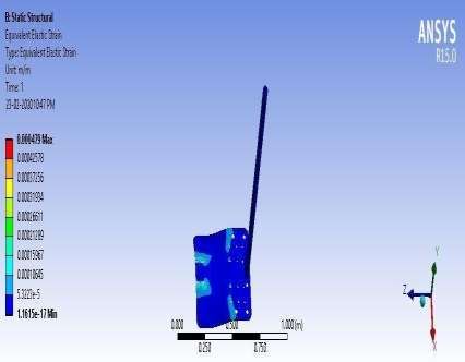
Mukt Shabd Journal                                                                             ISSN NO : 2347-3150

          2. Literature Review
               Ganesh Shirsath et.al. There is increase transportation of goods and public transportation.
          The adverse effects are known and well documented. Discussions about various views of the
          best solutions for these problems are taking place around the world. One of these visions
          involves the use of advanced technology based on the public transit as the basis for all
          sustainable solutions. In this search for different methods, MPTDs could help promote a
          modal transfer away from the automobile for short-distance trips. Electric scooters and
          Segways are two, user friendly, “in” modes of transportation that facilitate effortless travel
          and could provide suitable transportation in metro cities. Our aim is to make a design and
          fabrication of Segway personal transporter. The Segway is based on the principle of inverted
          pendulum that will keep an angle of Zero degrees with vertical at all times.
              Mayank Sharma et.al. The Segway Human Transporter is one of several low-speed
          transportation devices (e.g., bikes, scooters, wheelchairs) that, under certain circumstances,
          travel on sidewalks, roadways, and other shared-use paths. The objective of this research was
          to examine the primary operating characteristics of the Segway. In this thesis, we designed
          and constructed mechanically based system for a two wheel balancing Segway robot. In this
          paper we present a Segway based on gyro sensor, accelerometer along with a microcontroller
          and use of mechanical and electrical hardware’s. The dynamics of the vehicle is similar to the
          classical control problem of an inverted pendulum, which means that it is unstable and prone
          to tip over. This is prevented by electronics sensing the pitch angle and its time derivative,
          controlling the motors to keep the vehicle balancing. This kind of vehicle is interesting since
          it contains a lot of technology relevant to an eco-friendly and energy efficient transportation
          industry. This thesis describes the development of a similar vehicle from scratch,
          incorporating every phase from literature study to planning, design, vehicle construction and
          verification. The main objective was to build a vehicle capable of transporting a person
          weighing up to 70-80 kg and capable of travelling to some km distance with varying speed.
               Ashish Srivastava et.al. The present paper aims at expanding the use of two wheel system
          by creating a small, compact high performance control and instrumentation system that can be
          integrated into future transport systems. This system is based on the principle of inverted
          pendulum and is an electrically activated balancing machine with only two wheels with a
          feature to spin on the spot. This system manages to bring itself to the equilibrium point by
          creating an opposing force in the direction opposite to that of the user. The project explores
          the use of Kalman filter for sensor fusion and State feedback control algorithm for regulatory
          and tracking performance. This system may also be used as a test bed to investigate the
          performance of other control algorithms.
               Ankit S. Khanzode et.al. In this project work, two wheeled and one small supporting
          wheel self-balancing as well as manually balancing Mechanical Segway vehicle is prepared
          which is also known as a personal transporter Segway. The system is able to operate in
          transporter mode and robotic mode. The first goal is to maintain stabilization in pitch
          dynamic. This project focuses on to manufactured Segway without using any type
          programming & Sensors a state feedback to stabilize system on transporter mode. The system
          consist of forward and backward movement when the driver operating DPDT switch in
          transporter mode in order to stabilize body. Small wheel is used so that there is no need of
          gyroscope for balancing purpose. The aim of this project work is to build up at a very low
          cost, highly efficient rate and easy to handle and operating also. The tests are performed on
          mechanical Segway to confirm that Mechanical Segway operating very well and high
          efficient rate.
                Sandesh Pitambare et.al. In the present days, we are dealing with a problem of increase
          in number of vehicles with ever-lasting demand of fuel to run them. If this situation remains
          with time, it would be difficult for us to save our future from increasing pollution and fuel

Volume IX, Issue IV, APRIL/2020                                                                        Page No : 442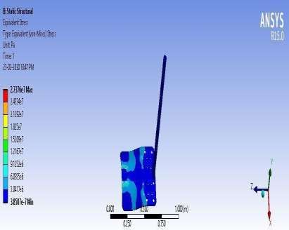
Mukt Shabd Journal                                                                            ISSN NO : 2347-3150

          demand. With time the population on earth increases obviously; which cannot be controlled
          so to fulfill the demands of fuel or energy in future world, effective steps should be taken as
          soon as possible. Our dependence on fuel can be reduced with an alternative such as, use of
          battery-operated vehicles. The aim of this project work is to build up an Tri-wheel electric
          segway at a very low cost, highly efficient rate and easy to handle and operating also. . Three
          wheels Segway is an electric scooter of future technology; it is often used to transport a user
          across mid-range distances in urban environment. It has more degrees of freedom than car or
          bike and is faster than pedestrian. They are more efficient than fuel powered vehicles for
          shorter distance and time of travelling.
          3. Development of prototype:
                  After studying different papers on Design & Fabrication of segway ,we have made our
          project motto as application of Design, Analysis & Fabrication of three wheel segway, by
          using low cost equipment under normal feasible conditions.
           In this project, we are using the equipment with low cost and the equipment can also sustain
          particular loads only. Because this project is for keeping the model with exact parts of
          segway, in this we are using Two plastic wheels, one supporting wheel, batteries and motors.
          So, the aim of this project centers around the concept of making a Segway type standup
          scooter that is Economical, Reliable, Stable and Fail-safe.
                  Parts used for fabricating the model.

                                      Table 1.euipment used
                  Description                       Type                         Quantity
                                                                                 required
                       DCMOTORS                 24 V , 50KG , 200RPM                  2
                       TWOWHEELS                Dia 12cm, width 3cm                   2
                       SWVELWHEEL               Dia 6cm                               1
                       BATTERY                   24V – 18AH                           1
                       SWITCHES                  POLARITY VARIES                      2
                                             ELECTRICAL WIRING EQUIP                  5
                  CONNECTINGWIRES
                      PIPE’S                       1.5M                                3
                      NUT BOLTS                   6MM DIA                               12

                         WOOD BOARD                25*30*3                              1

            4. Design and Analysis of three wheel segway.

                                    Fig. 4.1.1 Isometric view of the segway model.

          3D model of the segway is created using Solid Works 2013, a solid modeling computer-
          aided design (CAD) and computer-aided engineering(CAE) computer program developed by
          Dassault Systems Solid Works Corp

Volume IX, Issue IV, APRIL/2020                                                                       Page No : 443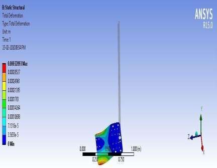
Mukt Shabd Journal                                                                              ISSN NO : 2347-3150

                           Table 2. List of machining operations carries out on the foot plate:

                    S.no   Operation carried out                  Machine used

                    1.     Cutting the plate to required          Horizontal hack saw machine
                           dimensions

                    2.     Rounding the corners and               Hand angle grinder
                           chamfering the edges

                    3.     Drilling the holes on the wood plate   Horizontal drilling machine
                           at required positions

                 After carrying out the required machining operations, the motors, bearings, drive
          wheels, swivel wheel and springs are mounted onto the footplate. After mounting the
          components under the foot plate, a handle made of GI pipes is fixed on to top of footplate by
          using a threaded flange coupling. After making the circuit wiring and connecting the
          electronics, the assembly of segway is shown in the. Two rechargeable lead acid batteries of
          12V each and of capacity 10AH each are connected in series are used to power the segway.

                                                                                                +
          4.1 .MODEL CALUCULATIONS:

          Taking,

          Total mass, m = 100 kg

          Angle of inclination, ϴ = 20˚

          Total efficiency, e = 85%

          Radius of the wheel, R = 0.1016 m

Volume IX, Issue IV, APRIL/2020                                                                       Page No : 444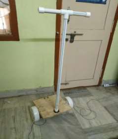
Mukt Shabd Journal                                                                            ISSN NO : 2347-3150

          Supply voltage, V = 24V

          Desired acceleration, a = 0.2 m/s²

          Let, the Segway speed on incline v = 2m/s = 120m/min.

          So, 2ΠRN = 120

          2×π×0.1016×N = 120

          This equation gives,

          N = 188 rpm.

          w = 19.6850 rad/sec.

          mgx = 100 × 9.81 × sin(20˚) = 89.59

          mgy =100 × 9.81 × cos(20˚) = 400.32

          Starting torque is given by,

          T = (100/85) × ((0.2 + (9.81×sin(20˚))×100×0.1016)) / 2 = 21.24 Nm

          Maximum current induced is given by,

          I = (21.24 × 19.6850)/24 = 17.428

          Battery capacity is given by
          C= 17.428 × (30/60) = 8.714 AH

          This is the battery capacity needed for each motor. To calculate battery capacity needed for
          entire segway, this should be multiplied by no. of motors.

          C= 8.714 × 2 = 17.428 AH.

          4.2 Analysis of segway:

                 The project began with exploring ideas for the design and inspired by similar devices
          in the market. Ultimately, a rectangular platform with two motor-powered wheels and one
          caster wheel was chosen. Parts were purchased and connected, and then model was built and
          tested. During testing, it was found that the model did not perform as well as expected.
          Because the motor did not able to grab the load of the specified battery what we have kept.
          And also we have designed some pictures in solid modeling software. Not only designing the
          model we have tested in stress strain analysis also for better result.

Volume IX, Issue IV, APRIL/2020                                                                          Page No : 445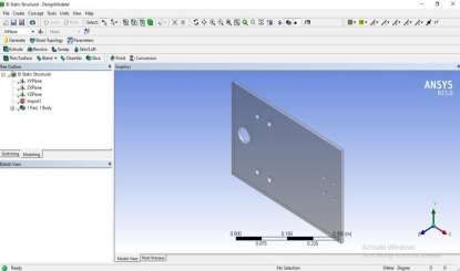
Mukt Shabd Journal ISSN NO : 2347-3150
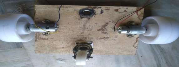
Fig. 4.2.1Top view of the model
The aim of this analysis is to check the deformation, stresses and strains induced due to
loading on the footplate of the segway. Here loading included the weight of the person,
weight of the batteries, motors and other components. However, the weight of
Before analysis a model of the foot plate is created using solid works. This model shows how
the foot plate looks after machining, with rounded corners and drilled holes for mounting
motors, bearings, handle and the swivel wheel. The areas with maximum stress would be the
gaps between the holes. The distance between these holes is maintained as maximum as
possible (without affecting the design), to minimize the stresses induced. The below picture
shows the model of the machined footplate created in Solid Works software that should be
analyzed for stresses, strains and deformation.
Fig.4.2.2 Foot plate modeled for analysis.
Since, the foot plate is supported by the bearings and the swivel wheel at three positions;
simply supported boundary conditions are given at the positions of the two Plummer block
bearings and the swivel wheel. Since, the weight acts at the standing positions of the person,
two uniformly distributed loads of 50 kg each are applied on either side of the footplate at the
standing positions areas. The same procedure is done using two point loads as well. Both
results are nearly same.
Total load = 100 kg
No. of positions = 2
Type of load = uniformly distributed
Type of analysis = Static Structural
Volume IX, Issue IV, APRIL/2020 Page No : 446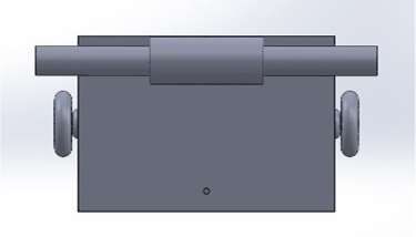
Mukt Shabd Journal                                                                            ISSN NO : 2347-3150

          4.3 STRESS – STRAIN ANALYSIS:

                        Fig. 4.3.1 Analysis results: Stress distribution on the foot plate.

                       Fig. 4.3.2 Analysis results: Equivalent Elastic strain of the foot plate.

          4.4 DEFORMATION:
                  The below picture shows the total deformation of the footplate in m. under the give
          conditions of loading and boundary conditions.

                       Fig. 4.4.1Analysis results: Total deformation of the footplate.

Volume IX, Issue IV, APRIL/2020                                                                         Page No : 447
Mukt Shabd Journal ISSN NO : 2347-3150
The resultant deformation style can be seen in above picture. The maximum deformation is
found at the bottom corners of the plate. The value of this maximum deformation is around
0.3mm.
Maximum deformation areas = Bottom corners of plate
Maximum deformation value = 0.3 mm
Since, the deformation is very small, it will not have much effect on the structure of the
plate under loading and there are no chances that this minute deformation affects the motion
or stability of the segway.
5. CONCLUSIONS:
The three wheel segway is designed based on the Fundamentals of machine design,
modeled in Solid works software and Analyzed in Ansys15.0 and fabricated according to
plan. Based on the factors like Stability and cost, three-wheel segway is found to be a good
alternative for the two-wheeled version. Moreover, the fail-safe feature in this vehicle makes
it more reliable than the two-wheel segway. The results from this project clearly shows that
three-wheel segway when manufactured with efficient components, good control system and
a good suspension system, can be the most stable, reliable, economical and fail-safe
personal transporter.
Basically this investigation is successful achieved the objective with the acceptable
outcome. The main goal of this project was a build in a prototype of two wheels and one
supporting wheels transporter and this goal has been fulfilled. The overall functionality and
performance of the vehicle has been evaluated thoroughly by a number of test drives. The
vehicle has been tested by a number of different weights. This project is implementing with
an idea to find an effective solution to transportation problem.
FUTURE SCOPE:
Less accurate bang-bang type control system can be replaced with Dual H-Bridge
control, which can make the steering of the segway more precise. 3rd wheel can be provided
with a better suspension system for more smooth movement of the vehicle Battery pack
capacity can be increased by replacing the lead acid batteries with polymer batteries, which
have much higher capacity for the same weight. This can improve the run time of the segway
before complete battery discharge. Steering mechanism of Segway can be improved by using
dual axis potentiometers. This makes the segway much easier to ride.
REFERENCES:
1. http://www.azom.com/article.aspx?ArticleID=11005
2. http://finalyearprojectsegway.blogspot.in/
Volume IX, Issue IV, APRIL/2020 Page No : 448Mukt Shabd Journal ISSN NO : 2347-3150
3. http://www.riobotz.com.br/riobotz_combot_tutorial.pdf
4. www.segway.com
5. http://www.instructables.com/id/Self-Balancing-segway-style-scooter-for-under-300/
6. http://www.instructables.com/id/Rideable-Segway-Clone-Low-Cost-and-Easy-Build/
7. www.robotshop.com/blog/en/drive-motor-sizing-tutorial-3661
8. www.robotplatform.com
9. http://finalyearprojectsegway.blogspot.in/
10. https://prototyperobotics.com/projects/the-seg-bot
11. http://science.howstuffworks.com/transport/engines-equipment/ginger.htm
12. http://motorcycle.michelin.asia/Home/Buying-Guide/Tyre-Basics/Speed-Rating-Lord-
Index
13. http://www.wheels-castors.co.uk/technique-guide/load-capacity.html
Volume IX, Issue IV, APRIL/2020 Page No : 449You can also read