Die-Hard - Operating and Maintenance Instructions - Elliott Tool
←
→
Page content transcription
If your browser does not render page correctly, please read the page content below
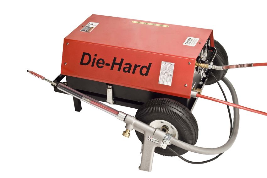
Die-Hard
  Cableless Tube Cleaning System

  Tube & Pipe Cleaners   Tube Testers   Tube Plugs   Tube Removal   Tube Installation

       Operating and Maintenance Instructions

www.elliott-tool.com
TABLE OF CONTENTS Introduction........................................................................................................... 4 Safety Guidelines.................................................................................................. 5 Operation Instructions........................................................................................... 7 Brush Sizing........................................................................................................ 10 Shut-Down Procedure......................................................................................... 12 Electrical.............................................................................................................. 13 Electrical Schematic............................................................................................ 16 Maintenance Instructions.................................................................................... 17 Technical Specifications...................................................................................... 21 Troubleshooting................................................................................................... 22 Diagrams & Parts List.......................................................................................... 24 Tube Measurements & Cleaning Schedule Records........................................... 31 Warranty.............................................................................................................. 33
INTRODUCTION
      Thank you for purchasing this Elliott product. More than 100 years of experience have been employed
      in the design and manufacture of this control, representing the highest standard of quality, value and
      durability. Elliott tools have proven themselves in thousands of hours of trouble-free field operation.

      If this is your first Elliott purchase, welcome to our company; our products are our ambassadors.
      If this is a repeat purchase, you can rest assured that the same value you have received in the past
      will continue with all of your purchases, now and in the future.

      The Die-Hard has been designed for the following types of equipment:

                                                 Heat Exchangers

                                                    Condensers

                                                      Chillers

                                                    Evaporators

      If you have any questions regarding this product, manual or operating instructions, please call Elliott
      at +1 800 332 0447 toll free (USA only) or +1 937 253 6133, or fax us at +1 937 253 9189
      for immediate service.

                         SERIAL NUMBER INFORMATION
      The contents of this technical manual apply only to Die-Hard Systems with serial numbers beginning
      with revision letter ‘C’:

      Example: C16001

      Record your Die-Hard serial number here for future reference:

      Model M5801-00 “Rev C”         Serial # ________________________________

4 Die-Hard
SAFETY GUIDELINES
Read and save all instructions. Before use, be sure everyone using this machine reads and
understands this manual, as well as any labels packaged with or attached to the machine.
! WARNING ! WARNING
To reduce the risk of injury, always
When using electric tools, certain unplug your machine before performing
safety precautions are required to any maintenance. Never disassemble
reduce the risk of electrical shock the machine or try to do any wiring
and personal injury. on the electrical system. Contact Elliott
for all repairs.
! WARNING ! WARNING
ELECTRIC HAZARD: EYE HAZARD:
Use the proper Wear protective
lockout and tagout glasses.
procedures before
servicing machine.
! WARNING NOTICE
Never allow the actuator to be Only use the Elliott Die-Hard Tube
pulled into the Auto-Feed Pump Unit Brushes. These brushes have been
assembly. Serious damage will occur designed to work with the Die-Hard
to both the Actuator and Auto-Feed Cleaner.
Pump Unit Assembly.
• Know Your Elliott Tool. Read this manual carefully to learn your tool’s application and
limitations as well as the potential hazards specific to this tool.
• Store idle machines in the horizontal operating position. When not is use, store your
machine in a dry, heated, secured place. Not storing your Die-Hard in its horizontal
operating position could result in pump oil loss through the Crankcase Check Valve
Oil Cap (This cap is designed to release pressure buildup in crankcase at 1 PSI. When
not stored in its horizontal operating position, oil will cover this Check Valve opening.
When pressure buildup is released, oil could escape from crankcase and into the Die-
Hard unit housing). For more information see “Preventative Maintenance Checklist” on
page 22.
• Stop the machine immediately if the hose stops feeding. Hose damage will occur if the
unit is operating when hose is restricted.
Die-Hard 5SAFETY GUIDELINES
• Use the proper brush to fit the tubes to be cleaned. Never use a brush that is too large.
Failure will result if too great a resistance is placed on the hose.
• Never place the Actuator in a vice or use pliers to grip the outside diameter of the
Actuator. Use only the wrench flats provided to install or remove the Actuator from the
Auto-Feed Hose. Use only the wrench flats provided to install or remove a brush from
the Actuator shaft. Serious damage can be caused to the Actuator by placing it in a
vice or other gripping device.
• Never leave your Die-Hard in direct contact with rain or directly spray water on the
unit. Store indoors away from weather in a dry location.Ground Your Elliott Tool.
Always use properly grounded electrical outlets, and if using an extension cord, make
sure that it is of the proper size for the electrical load and it is equipped with a ground
wire and ground plug. See “Technical Information” section for further information.
• Do not operate this machine while tired, distracted, under the influence of drugs or
alcohol or on medication that causes decreased control.
• Keep work area clean and well lit.
• Do not force a machine or attachment to do a job or operate at a speed it was not
designed for.
• Check for misalignment, binding of moving parts, improper mounting, broken parts
or any other conditions that may affect operation before use. Inspect all fasteners
for tightness to ensure there are no loose nuts or bolts that may inhibit operation. Do
not use a damaged machine. Repair or replace any defective parts prior to use of the
machine.
• Use proper accessories and use Elliott accessories only. For all repairs, insist on only
identical replacement parts.
• Always use properly grounded electrical outlets, and if using an extension cord, make
sure that it is of the proper size for the electrical load and it is equipped with a ground
wire and ground plug.
• Use only extension cords and plugs approved for outdoor use when working outdoors.
• Use appropriate safety equipment (i.e. safety glasses, ear plugs, dust masks, safety
boots, etc) when using this machine.
• Ensure that long hair or loose fitting clothes are secure prior to use of the machine.
• Always disconnect the machine from the power source prior to performing any
maintenance or repairs.
• Labels and Nameplates carry important information and will assist you in ordering
spare and replacement parts. If unreadable or missing, contact an Elliott service facility
for a replacement.
• Maintain machine carefully. Keep handles dry, clean and free from oil and grease.
Follow instructions for lubricating and changing accessories. Periodically inspect
the machine cord and extension cords for damage. Have damaged parts repaired or
replaced by an Elliott service facility.
6 Die-HardOPERATION INSTRUCTIONS
1. Position the Auto-Feed Pump Unit at a right angle to the tube sheet being cleaned (Fig 1, Page
13). The Auto-Feed Gun Assembly connection is closest to the tube sheet being cleaned but is
a minimum of 6’ from the face of the tube sheet. When cleaning large diameter vessels, position
the Auto-Feed Pump Unit facing the tube sheet being cleaned in the center of the tube sheet,
keeping a minimum 6’ distance to the tube sheet. Note: When moving from tube to tube, avoid
sharp bends in the Auto-Feed Gun Assembly hose, keep the Auto-Feed Gun Assembly hose in
generous arches from the handle to the Auto-Feed Pump Unit.
2. Unwind the Power Cord from the storage hooks.
3. Connect the Power Cord into an appropriate electrical source. Connect the Trigger Switch Feed
Gun or Footswitch into socket flange mounting on the Die-Hard unit. Check “Reset” button on
the GFCI to insure it is engaged. The “power” indicator light will be illuminated when power is
flowing to the cleaner. For more information see “Electrical” section of this manual.
4. Connect a municipal water supply to the Auto-Feed Pump Unit. Be sure the Inlet Strainer is in
place within the Hose Connection on the Auto-Feed Pump Power Unit before making this
connection. This is a standard water hose connection and a garden hose can be used for this
supply. A minimum 5/8” diameter hose is recommended.
5. Turn on the water pressure to the Auto-Feed Pump Unit, then immediately turn the water
pressure off. This is done to prevent the pump from being operated “Dry”. The quantity of
water under pressure in the garden hose will supply enough water to the pump to prevent
damage during the remainder of the set-up operation. IMPORTANT: Never operate the Die-Hard
Cableless Tube Cleaner dry. Damage to the high-pressure pump could result from operating
the system without a connection to a water supply. Always follow the directions provided in this
manual to prevent costly pump damage.
6. Uncoil Auto-Feed Hose and push the Actuator connection end into the Auto-Feed Pump Unit
until it stops. NOTE: Do not assemble Actuator to the Auto-Feed Hose at this time, serious
damage will result if Actuator is pushed through the Feeding Unit in the Auto-Feed Pump Unit.
IMPORTANT: Do not push swivel fitting end into Auto-Feed Pump Unit. This will damage the
Auto-Feed Hose and potentially the Auto-Feed Unit.
7. Depress the top side of Trigger Switch or “IN” side of the Footswitch (while applying a slight
pushing motion to the Auto-Feed Hose. The Feeding Unit within the Auto-Feed Pump Unit will
engage and pull the Auto-Feed Hose through the unit until it exits from the Auto-Feed Gun
Assembly Connection. Allow approximately 12” of Auto-Feed Hose to exit the Auto-Feed Pump
Unit and stop the feeding action of the hose by removing your finger from the Trigger, or foot
from the Footswitch.
8. Uncoil the Auto-Feed Gun Assembly and install the correct clear nosepiece to the handle
corresponding to the tube diameter being cleaned.
9. Locate the end of the Auto-Feed Gun Assembly, insert the exposed Auto-Feed Hose into the
Auto-Feed Gun Assembly Connector, and connect it to the Auto-Feed Pump Unit. Screw the
connector nut onto the Auto-Feed Gun Assembly connector HAND TIGHT. Do not over- tighten
this connection; tools are not required for this operation.
10. Attach the clear plastic Drain Tube to the Feeding Handle. You may connect a standard garden
hose to the end of the Drain Tube to provide additional length so water can be directed to a floor
drain. Be aware that this tube will contain contaminates from tubes being cleaned.
11. With the Auto-Feed Gun Assembly hose in generous arches, grab the handle of Auto-Feed Gun
Die-Hard 7OPERATION INSTRUCTIONS
Assembly. Depress the top side of the Trigger or “IN” side of Footswitchand allow the Auto-
Feed Hose to be fed through the Auto-Feed Gun Assembly until approximately 6” of Auto-Feed
Hose is exposed outside the nosepiece then stop. IMPORTANT: When the Trigger or Footswitch
is depressed a small amount of water will exit the Auto-Feed Hose Connection on the Auto-
Feed Pump Assembly. This is normal and will occur each time the Trigger or Footswitch is
depressed during set-up. This small quantity of water will keep the pump lubricated during the
set-up operation.
12. Select the appropriate brush size for the tubes being cleaned. For more information see “Brush
Sizing” section.
13. Select an Actuator and screw the correct size brush onto the Actuator. Locate the wrench flats
on the Actuator and use the wrenches provided to tighten the brush and locknut to the Actuator
Connection. Tighten the Locknut to the Actuator Connection to prevent the brush from coming
loose during operation. IMPORTANT: Never use a vise or pliers to hold the body of the Actuator
when tightening brushes to the Actuator. Serious damage can occur to the Actuator if clamping
pressure is applied improperly.
14. Screw the Actuator and brush to the connection on the Auto-Feed Hose. Remember use the
wrench flats located on the Actuator with the wrenches provided to tighten this connection to
the Auto-Feed Hose.
15. Lay Auto-Feed Hose in large loops on floor behind Auto-Feed Pump Unit. Loosen the screws
that hold the Hose Stop Assembly on the Auto-Feed Hose and move the stop away from
contact with the Auto-Feed Pump Unit.
16. The automatic stop is now ready to be set to the proper length of the vessel. Press on the top
side of the Trigger or “IN” side or Footswitch and feed out a length of Auto-Feed Hose that is
approximately the same length as the vessel being cleaned. Position the nosepiece against
the tube sheet being cleaned, then walk to the opposite end of the vessel with the Actuator
and brush assembly. Holding tension on the brush and Actuator make sure that only the
brush will exit the opposite end of the vessel during the cleaning operation. IMPORTANT: This
measurement is critical; do not allow the Actuator to exit the tube during operation. Damage
to the Auto-Feed Hose and Actuator can occur if the Actuator catches on the end of the tube
during retraction of the Auto-Feed Hose.
17. Walk to the pump unit and slide the spring and Hose Stop Assembly over the Auto-Feed Hose
until the end of the spring cap comes into contact with tube on the Auto-Feed Pump Unit.
Depress the Hose Stop Assembly approximately 3” creating spring pressure against the tube
end and tighten the screws on the Hose Stop Assembly with the wrench provided.
18. Depress the button side of the Trigger or “OUT” side of Footswitch to pull the Auto-Feed Hose
and Feeding Nozzle back into the Handle Assembly. “Bump” or use repeated short Trigger or
Footswitch pulses to return Actuator and brush assembly inside the clear Nozzle. Stop when the
Actuator and brush assembly are visible in the clear nozzle.
19. Turn on the water pressure to the Auto-Feed Pump Unit.
20. Connect the Auto-Feed Hose to the Auto-Feed Pump Unit. This connection is supplied with a
“quick slide” connector to eliminate hose rotation during operation.
21. The unit is now ready to clean tubes. Position the nozzle at the end of the first tube to be
8 Die-HardOPERATION INSTRUCTIONS
cleaned.
22. Depress the top side of the Trigger or “IN” side of Footswitch to start the feeding action of the
cleaner. NOTE: Keep the nozzle level and in contact with the tube at all times during the
cleaning cycle. Keep the Trigger or Footswitch depressed until the pump unit automatically
shuts off when the brush reaches the opposite end of the vessel being cleaned. Remove your
finger from the top side of the Trigger or foot from Footswitch, move to the bottom side and
depress the Trigger or “OUT” side of Footswitch.
23. The Auto-Feed Pump Unit will draw the Auto-Feed Hose back through the tube. Watch the
returning Auto-Feed Hose through the clear Nosepiece Nozzle and stop the unit when the
Actuator is visible in the clear Nozzle.
24. Move to the next tube and repeat the process until all the tubes have been cleaned.
25. Check all screw connections periodically to ensure they are tight.
26. The machine is now ready to operate.
IMPORTANT: Monitor the travel of the Auto-Feed Hose through the clear nozzle or as the hose enters
the Auto-Feed Pump Unit.
If an obstruction in the tube prevents the brush and Actuator from passing through the tube, remove
your finger from the Trigger or foot from the Footswitch. Depress the bottom side or “OUT” side of
Footswitch, and move the brush and Actuator about 2’ then depress the top side of the Trigger or “IN”
side of Footswitch until the brush passes the tube restriction. If the brush and Actuator still will not
pass, repeat the process of reversing direction slightly, then forward against the obstruction until it is
clear. Do not keep the Trigger or Footswitch depressed if the Auto-Feed Hose is not moving through
the tube. This will result in premature Auto-Feed Hose wear.
! WARNING
This machine powers cleaning devices. It is recommended that
the operator wear safety glasses with side shields or full face
shield eye protection, gloves and water repellant, nonskid foot
wear. Avoid contact with objects other than the tube when the
machine is in operation.
NOTE: Operate the Auto-Feed Handle Assembly as straight as possible to minimize any sharp radius
bends. This applies to both brush insertion and maximum cleaning length. Allowing the cleaning
device to exit the tube can cause premature failure in the Actuator Coupling area. Never exit the
tube with the tube cleaning device in operation. For more information see “Start Up Operation”
section.
NOTE: Start to clean the tube bundle from the top of the unit to the bottom. Clean the bundle one row
at a time, marking with soapstone, each row of tubes that have been cleaned.
Die-Hard 9BRUSH SIZING
Sizing your brushes correctly to the tubes being cleaned is a critical step in operating your Die-Hard
Cableless Tube Cleaner. Its cleaning technique incorporates a unique design unlike any on the market
today, and will require your attention to use your Die-Hard to its full potential.
Improper brush selection will prevent the “scrubbing” action of the system and will not allow the
feeding of the brush through the tube.
1. Use a measuring device inside the tubes to determine the inside diameter of the tubes. NOTE:
Measure the tubes at a point away from the expanded section of the tube. An Elliott Tube Gage
is recommended for this operation as it has an extended reach to enable this measurement to
be taken at the appropriate location within the tube.
2. Select the brush diameter which is the closest to the measured tube ID. Note: Applies to both
prime surface and internally enhanced tubes.
If no measuring device is available, use the following general brush sizing techniques:
1. For prime surface tubes and internally enhanced tubes, select a brush slightly smaller than the
ID of the expanded portion of the tube.
2. Thread the brush onto the Actuator before connecting the Actuator to the Auto-Feed Hose.
Using your thumb and forefinger holding the Actuator, insert the brush into the tube past the
rolled /expanded area of the tube.
3. Once the brush is inserted past the expanded tube end pull the brush out of the tube. If you
experience any type of significant resistance from the brush, the brush is too large. Source
anther brush that is a size smaller and repeat the insertion process until you experience very
little, to nearly no resistance from your brush.
NOTE: Too large of a brush will restrict proper function of the Auto-Feed Hose and pulsing
action of your Die-Hard unit.
IMPORTANT: These brush sizing techniques are regarded as general, and may vary depending on
brush condition, tube deposit thickness, depth of internal enhancements, etc. Use only Elliott Die-Hard
brushes. Do NOT select a brush with too large a diameter. This will impede the feeding of the Auto-
Feed Hose, causing damage to its outer casing. If the Auto-Feed Hose feeds at a slower rate than its
intended 3 ft/sec, try using the next brush size smaller in diameter.
10 Die-HardOPERATING POSITION
Figure 1
Die-Hard 11SHUT DOWN PROCEDURE
1. After all the tubes have been cleaned, shut off the water to the Auto-Feed Pump Unit.
2. Hold the Feeding Handle away from the tubes and tube sheet and depress the top side of the
Trigger or “IN” side of Footswitch, feed out the brush and Actuator from the clear nozzle.
IMPORTANT: Serious damage will result if Actuator is pulled through the Feeding Unit in the
Auto-Feed Pump Unit.
3. Remove the Actuator and brush from the Auto-Feed Hose. DO NOT FEED THE ACTUATOR
THROUGH THE AUTO-FEED PUMP UNIT.
4. Disconnect the Auto-Feed Hose Assembly from the Auto-Feed Pump Unit.
5. Depress the bottom side of the Trigger or “OUT” side of Footswitch and allow the Auto- Feed
Hose to be pulled through the Auto-Feed Gun Assembly and Auto-Feed Pump Unit until the
Auto-Feed Hose stops.
6. Remove the Auto-Feed Hose from the Auto-Feed Pump Unit.
7. Remove the Auto-Feed Handle Assembly from the Auto-Feed Pump Unit.
8. Unplug the Power Cord from the electrical source and wind the Power Cord on the “hooks”
provided on the Auto-Feed Pump Unit. IMPORTANT: Store Die-Hard in its horizontal operating
position only. Serious damage to pump could occur.
If the Auto-Feed Pump Is Exposed To Freezing Temperatures:
1. Anti-Freeze solution must be used to keep the pump from freezing.
2. Remove the Drain Tube from the Auto-Feed Handle Assembly and flush using clear water to
remove any remaining contaminates from the tube cleaning operation.
3. Screw the “male” Drain Tube connector to the Auto-Feed Pump Unit hose connection.
4. Screw the Antifreeze Adapter onto the Elliott Antifreeze Bottle.
5. Screw the “female” end of the Drain Tube onto the Antifreeze Adapter.
6. Turn the container of Anti-Freeze Solution upside down allowing the Anti-Freeze Solution to fill
the Drain Tube.
7. Activate the Auto-Feed Pump Unit by depressing either the top or bottom side of the Trigger or
either side of Footswitch. DO NOT ACTIVATE THE PUMP UNIT IF THE AUTOFEED HOSE IS
ENGAGED WITHIN THE AUTO-FEED PUMP UNIT.
8. Watch the discharge of fluid from Auto-Feed Hose connection on the Auto-Feed Pump Unit.
9. When this discharge becomes the same color as the Anti-Freeze solution in the container,
remove your finger from the Trigger or foot from the Footswitch and stop the unit.
10. Remove the Antifreeze Adapter from the Antifreeze container and replace the cap.
11. Remove the Drain Tube from the Auto-Feed Pump Unit.
12 Die-HardELECTRICAL
Your Elliott Die-Hard has been designed to require a grounded electrical receptacle of 120 volts, single
phase, 20 amps A.C. current. Serious damage to the unit can occur within the electrical components
if the electrical supply, voltage, and amperage rating does not meet this requirement. An electrical
diagram is supplied with this manual as a reference (Fig 2, page 18). Only a qualified electrician
should use the electrical diagram to perform any maintenance or repairs.
This machine requires electrical grounding. A three prong grounding plug must be used with this
machine. The plug must be connected to a properly grounded outlet (see Diagram C). If the machine
should electrically malfunction or breakdown, grounding provides a low resistance path to carry
electricity away from the user, reducing the risk of electrical shock.
The grounding prong in the plug is connected through the green wire inside the cord to the grounding
system in the machine. The green wire in the cord must be the only wire connected to the tool’s
grounding system and must never be attached to an electrically “live” terminal.
Your machine must be plugged into an appropriate outlet, properly installed and grounded in
accordance with all codes and ordinances. A temporary adapter may be used for connecting
grounded plugs to two prong outlets. The green rigid ear or lug extending from the adapter must
be connected to a permanent ground such as a properly grounded outlet box or receptacle. Simply
remove the center screw from the outlet, insert the adapter and reattach the screw through the green
grounding ear to the outlet. If in doubt of proper grounding, contact a qualified electrician. A temporary
adapter should only be used until a properly grounded outlet can be installed by a qualified electrician.
(See Diagram D) The Canadian Electrical Code prohibits the use of temporary adapters.
! WARNING
Improperly connecting the grounding wire can result in the risk
of electric shock. Check with a qualified electrician if you are
in doubt as to whether the outlet is properly grounded. Do Not
modify the plug provided with the machine. Never remove the
grounding prong from the plug. Do Not use the machine if the
cord or plug is damaged. If damaged, have it repaired by an
Elliott service facility before use. If the plug will not fit the
outlet, have a proper outlet installed by a qualified electrician.
Die-Hard 13ELECTRICAL
Diagram C
Diagram D
Extension cords may be used with the machine, providing the cord is equipped with three wires,
12 gauge in size, with ground plugs and not longer than 50’ in length. Using extension cords with
inadequately sized wire causes a serious drop in voltage resulting in possible machine damage. The
smaller the gauge number of the wire, the greater the capacity of the cord. For example, a 12 gauge
cord can carry a higher current than a 14 gauge cord.
• • If you are using an extension cord outdoors, be sure it is marked with the suffix “W-
A” (“W” in Canada) to indicate that it is acceptable for outdoor use.
• Be sure your extension cord is properly wired and in good electrical condition. Always
replace a damaged extension cord or have it repaired by a qualified person before
using it.
• Protect your extension cords from sharp objects and excessive heat.
14 Die-HardELECTRICAL
Ground Fault Circuit Interrupter Test
Your Elliott Die-Hard is equipped with a Ground Fault Circuit Interrupter located on the power cord.
This device provides added protection in reducing the risk of electric shock. You should “test” the
GFCI receptacle prior to each new operating use. Testing of the GFCI device is as follows:
1. Plug machine into proper electrical outlet.
2. Locate the Ground Fault Circuit Interrupter and push the “test” button with your finger. Never
use any other device to push the test button.
3. An audible “click” should be heard when the button is depressed.
4. Engage the Trigger or Footswitch of the machine. The machine Should Not operate.
5. Release the Trigger or Footswitch of the machine, locate and push the “reset” button with your
finger.
6. Engage the Trigger or Footswitch of the machine. The machine should operate normally.
! WARNING
If the machine should fail this testing process,
contact an Elliott service facility immediately. Do
Not attempt to use the machine in this condition.
An electric shock could occur if there is a
malfunction of the GFCI circuit.
Die-Hard 15ELECTRICAL SCHEMATIC
Figure 2
16 Die-HardMAINTENANCE INSTRUCTIONS
! WARNING
To reduce the risk of injury, always unplug your
machine before performing any maintenance.
Never disassemble the machine or try to do
any rewiring on the machine’s electrical system.
Contact Elliott for all repairs.
Keep your Die-Hard in good repair by adopting a regular maintenance program. Before each use,
examine the general condition of your machine. Inspect Trigger Switch connections, foot switch,
machine cord set and extension cords for damage. Check for loose screws, misalignment, binding
of moving parts, improper mounting, broken parts or any other condition that may affect its safe
operation. If abnormal noise or vibration occurs, turn the machine off immediately and have the
problem corrected before further use. For more information see “Trouble Shooting” section. DO NOT
USE A DAMAGED MACHINE. Tag damaged machines “DO NOT USE” until repaired.
Under normal conditions lubrication of the machine between uses is not necessary.
Clean dust and debris from vents. Keep the machine handles clean, dry, and free of oil or grease.
Your machine has been finished with a paint coating that is very durable and should last the life of the
machine. Use only mild soap and a damp cloth to clean your machine. Certain cleaning solvents may
be harmful to the painted surfaces. Never use flammable or combustible solvents around machines.
! WARNING
DO NOT expose the pump and valves within the
Auto-Feed unit to freezing temperatures, without
antifreeze protection.
After every cleaning season or 12 months remove the machine cover and check the “V” belt for
cracking and wear. Start the next cleaning season by operating the machine prior to starting a new
job. For more information on proper operation see “Operation” section.
Die-Hard 17MAINTENANCE INSTRUCTIONS
Antifreeze
If the unit will be exposed to freezing temperatures the pump and valves within the Auto-Feed Pump
Unit need to be protected against freezing. A high quality antifreeze solution must be used to prevent
damage to the ceramic pistons within the high-pressure pump. Use only approved antifreeze products
listed below; unapproved products could cause damage to the seals within the pump.
• Antifreeze solution supplied by Elliott (Propylene Glycol)
• Ethylene glycol based automotive antifreeze
IMPORTANT: Ethylene Glycol based automotive antifreeze is toxic, follow directions for its proper use,
handling, disposal and storage. Elliott antifreeze is non-toxic and is generally regarded as safe by U.S.
Government. If unit has been exposed to freezing temperatures, allow the unit time to “warm up” prior
to using.
Crankcase Oil Change
Change the oil in the pump crankcase after first 50 hours of operation. Follow the schedule on the
“Preventative Maintenance Check List” thereafter, or at the end of every cleaning season.
1. Ensure that the power cord has been removed from any 120 Volt power source.
2. Remove the cover of the Auto-Feed Pump Unit by removing the 10 Phillips Head Screws.
3. Locate the Crankcase Check Valve on the top of the Pump Crankcase.
4. Remove the Crankcase Check Valve.
5. Place an oil drain pan on a flat surface.
6. Use the two grab handles on each end of the Auto-
Feed Pump Unit and turn the unit upside down with the
draining oil from the Pump Crankcase flowing into the
drain pan.
7. After all of the oil has drained from the Pump Crankcase
rotate the unit back to the upright position.
8. Use a soft cloth to wipe up any spilled oil from the
inside of the Auto-Feed Pump Unit Housing.
9. Use a funnel to assist in filling the Pump Crankcase with
only SAE 30 NON-DETERGENT OIL. IMPORTANT:
Use only SAE 30 NON-DETERGENT OIL in the Pump
Crankcase, use of a Detergent type oil will damage
internal pump components and void manufacturers
warranty.
10. Check oil level using the Site Gage on the end of the
Crankcase Housing. Fill slightly past the RED DOT on
the Site Gage. DO NOT FILL PAST SITEGLASS TOP!
11. Replace the Crankcase Check Valve in the Pump Crankcase.
12. Replace the cover and secure with the 10 Phillips Head Screws.
18 Die-HardMAINTENANCE INSTRUCTIONS
Actuator
To replace the Actuator spring:
1. Loosen the 3 Stainless Steel set screws on Brush Adapter.
2. Apply localized heat to the Brush Connector threads to
approximately 250°C. Disassemble while hot. Remove
Brush Adapter by unthreading from the Piston Rod. A
screwdriver slot has been supplied at the back of the
Actuator to assist in this removal process. Remove
the nylon washer. Use a thread locking solvent and
mechanical abrasion such as a wire brush to clean
threads.
3. Apply localized heat to the Rear Adapter threads to
approximately 250°C. Disassemble while hot. Use wrench
flats to remove the Rear Adapter from the Actuator. Use a
thread locking solvent and mechanical abrasion such as a
wire brush to clean threads.
4. Remove the Piston, Spring, and Piston Rod from the body
of the Actuator.
5. Remove and replace the Spring from the Piston Rod.
Reassemble in reverse order. Remember to use a medium
to high strength thread locking compound when replacing
the Rear Adapter and Brush Connector – do not apply to
Set Screws.
NOTE: Do not allow thread locking compound to enter the
Piston area of the Actuator.
Die-Hard 19MAINTENANCE CHECKLIST
Initial 50 200 500 1500 3000
Check Daily
Hours Hours Hours* Hours** Hours**
Clean Inlet Strainer X
Clean Solenoid Strainer X
Oil Leaks X
Water Leaks X
Belts, Pulley X X X X
Plumbing X X X X
Initial Oil Change SAE 30 Non-Detergent X
Oil Change SAE 30 Non-Detergent X X X
Valves typically require changing every other seal change. Duty cycle, temperature, quality of pumped water, and inlet feed conditions
effect the life of the pump, wear parts and service cycle.
** Remember to service the regulator/unloader at each seal servicing and check all system accessories and connections before
resuming operation.
Refer to this manual for additional assistance.
*Oil Change SAE 30 Non-Detergent every 500 hours.
TORQUE CHART
20 Die-HardTECHNICAL SPECIFICATIONS
Motor
1 H.P. Electric Motor, 110/220 Volts, Single Phase, 60 Cycles, 6.8 Amps (220V)
Pump
4.2 GPM Max., 100-2200 PSI Max., 1725 RPM Max. Crankcase Oil Capacity 11.5 oz.
G. F. C. I. Electrical Rating
120 Volts, 15 Amps, 1800 Watts, 50/60 Hz.
Dual Voltage Power Transformer
115/230 Volts, 50/60 Hz, 24.0 Volts CT @ 1.25 Amps Output
Trigger / Footswitch Socket Flange Mounting
24.0 Volt Control
Overall Base Size (w/ cover)
24.3” x 15.03” x 9.6” (617.2 x 381.0 x 243.8 mm)
Connections
3/4” Hose Connection, 1/8-27NPT Auto-Feed Hose Connection
Unit Weight w/out Auto-Feed Accessories
97 lbs. (44.0 kg)
Total Unit Weight w/ Auto-Feed Accessories
104 lbs. (47.2 kg)
Die-Hard 21TROUBLESHOOTING
PROBLEM PROBABLE CAUSE SOLUTION
No Power Flow GFCI not in "Reset" mode Press "Reset" button on GFCI located at plug
connection of power cord
Hose Not Feeding - Feeding Pump shaft rotates but feeding unit does not Check set screw in coupling jaw, tighten screw
unit not rotating rotate
Hose Not Feeding - Feeding Hose will not feed out side of tube Check hose casing for grease or oil, wipe off
unit rotates hose casing
Hose will not feed inside of tube Check tube ID if measurement is less than
.520" tube is too small
Hose will not feed, pump is not pumping Check belt tension, replace belt if broken
water (M5801-01-1126)
Hose feeds into tube but stops Tube is obstructed, back up & try again if
unable to pass tube is blocked
Actuator Brush on Actuator moves a short distance Broken Actuator Spring, replace Actuator
easily by hand Spring (M5801-04RK)
Actuator does not move during operation Actuator Body is bent, replace Actuator
(M5801-04)
Auto-Feed Hose Assembly Hose feeds past initial stop setting Tighten Stop Coupling cap screws
Low Pressure Belt slippage Tighten belt or install new belt
Air leak in inlet plumbing Tighten hose fitting
Relief valve stuck, partially plugged or Clean/adjust relief valve. Replace defective
improperly adjusted components
Inlet strainer clogged Clean filter and replace in hose connection
Solenoid strainer clogged Clean strainer and replace solenoid
(M5801-01-2139)
Leaky Auto-feed Hose Replace Auto-feed Hose (M5801-02-45)
Inadequate water supply Check for water flow in inlet hose, or replace
with larger diameter hose
Worn or dirty inlet/discharge valves Clean inlet/discharge valves
Water Leak - Under the unit Leaking valves or seals Contact Elliott for repair or assistance
Water Leak - Into the Humid air condensing into water inside Install oil cap protector, change oil every 3
crankcase crankcase months or 500 hours
Lack Of Cleaning Power/ Loose belt Tighten belt
Poor Cleaning
Knocking Noise - Inlet supply Inadequate inlet water supply Make sure water supply is turned on to the unit
22 Die-HardTROUBLESHOOTING
PROBLEM PROBABLE CAUSE SOLUTION
Knocking Noise - Bearing Broken or worn bearing Replace bearing (M5801-01-0718)
Knocking Noise - Pulley Loose pulley on crankshaft Check key & tighten set screw
Knocking Noise - Coupling Loose coupling on shaft between pump & Check neoprene "spider" between coupling
feeding unit jaws, replace if worn (M5801-01-0783)
Oil Leak - Bubble gage Loose bubble gage Tighten bubble gage
Oil Leak - Crankcase check Loose check valve, excessive oil in Tighten check valve, fill crankcase to specified
valve crankcase or stored in a position other than level, store unit In a horizontal operating
its horizontal operating position position
Loose 45o street elbow or check valve Tighten elbow/check valve. Store horizontally if
possible.
Pump Runs Rough - Inlet Restricted inlet or air entering the inlet Correct inlet size plumbing, check for tight seal
conditions plumbing on hose connection
Pump Runs Rough - Pump Stuck inlet/discharge valves Cleanout foreign material
valves
Premature Seal Failure Running pump dry DO NOT RUN PUMP WITHOUT LIQUID
Starving pump of adequate water Increase hose one size larger than inlet port
size
Die-Hard 23DIAGRAM & PARTS LIST
25
65
49
91
52 70
75 21
38 68
81
1 51 66 46
78
80 43 69
59 79
45 14
73
26 25 30 98
44 64
10 53
41
39
26 76
18 16 42
67
92 33 12 14
22
26 60
92
85 11 7 15
29
86 93 24
82
72
22
83
38
20
47
23
48 90
2 87
89
4
9 84
54 19
63
50
34 40
35
94 37
36 6 8
15
97
17 13
25 99
96 58 15 71
88 77 57 55 32 28 3 5 29
56 95 74 62 61
24 Die-HardDIAGRAM & PARTS LIST
PARTS LIST PARTS LIST
ITEM QTY PART NUMBER DESCRIPTION ITEM QTY PART NUMBER DESCRIPTION
1 1 06201 1 HP MOTOR 54 1 M5801-01-201 GEAR HOUSING
2 4 127C ROUND HEAD MACHINE 55 1 M5801-01-202 SIDE PLATE
SCREW, #8-32 X 2-1/4 56 1 M5801-01-204 STOP PLATE
3 5 130BB HEX HEAD CAP SCREW, 57 1 M5801-01-205 DRIVE SHAFT
5/16-18 X 5/8 58 1 M5801-01-207 INLET FEED TUBE
4 4 130BC HEX HEAD CAP SCREW, 59 1 M5801-01-211 HOUSING BASE
5/16-18 X 3/4 60 1 M5801-01-2111 MALE CONNECTOR BARB
5 4 131A HEX HEAD CAP SCREW, M6 61 1 M5801-01-2114 FILTER SCREEN
X 1.0 X 35MM 62 1 M5801-01-2115 GARDEN HOSE ADAPTER
6 9 133A LOCK WASHER, 5/16 63 1 M5801-01-2116 HOSE BARB ADAPTER
7 8 133M LOCK WASHER, M6 64 1 M5801-01-2117 ELBOW HOSE BARB
8 5 169U WASHER, 5/16, 18-8 ADAPTER
STAINLESS STEEL 65 1 M5801-01-212 HOUSING COVER
9 1 171A HEX NUT, 1/4-20 66 1 M5801-01-2120 HEX BUSHING, 1/2 X 3/8
10 1 171SS HEX NUT, #10-32 67 1 M5801-01-2121 1/2 HEX HEAD PLUG
11 8 171W HEX NUT, M6 68 1 M5801-01-2127 SHEAVE
12 1 41-50785K431 1/4 STREET ELBOW 69 1 M5801-01-2129 SHEAVE
13 1 41-50785K61 HEX BUSHING, 1/4 X 1/8 70 2 M5801-01-213 CORD WRAP
14 2 41-50785K63 HEX BUSHING, 3/8 x 1/4 71 1 M5801-01-2139 SOLENOID VALVE
15 3 41-5454K87 1/4 BULKHEAD FITTING 72 1 M5801-01-2150 EXIT FEED TUBE
16 4 41-92510A777 SPACER 73 1 M5801-01-2152 TRANSFORMER
17 2 41-98870A110 KEY, 1/8 74 1 M5801-01-2155 1/4 MALE ELBOW
18 1 52-997171 24V MOTOR REV 75 1 M5801-01-2163 ENCLOSURE
CONTACTOR 76 1 M5801-01-2174 TERMINAL STRIP
19 2 539F SHOULDER SCREW, 1/4-20 77 1 M5801-01-2181 GUARD
X 3/8 78 1 M5801-01-2182 HIGH PRESSURE WATER
20 4 546C ELASTIC LOCKNUT, 5/16-18 PUMP
21 2 546D ELASTIC LOCKNUT, 1/4-20 79 1 M5801-01-2184 PRESSURE REGULATOR
22 6 546E ELASTIC LOCKNUT, #6-32 80 1 M5801-01-2191 SNAP ELBOW STRAIN
23 4 546H ELASTIC LOCKNUT, #8-32 RELIEF
24 1 546Y ELASTIC LOCKNUT, #2-56 81 36 M5801-01-2192 CABLE
25 15 577-4 THREAD-CUTTING SCREW, 82 1 M5801-12 FAN
#10-32 83 1 M5801-13 FAN POWER CORD
26 7 584-1 HEX HEAD DRILLING 84 1 M5801-15 WIRE FAN GUARD
SCREW, #12-14 X 3/4 85 1 M5808-09 SOCKET FLANGE
28 4 587-1 FENDER WASHER, 5/16 MOUNTING
29 12 587-2 FENDER WASHER, M6 86 1 M5808-12 FLANGE MOUNTING CAP
30 1 595-1 EXTERNAL TOOTH LOCK 87 8 P535-28 FLAT HEAD CAP SCREW,
WASHER, #10 M6 X 20
31 1 ETTLBL5500A LOGO LABEL 88 2 P8286-50NS RETAINING RING, SPIRAL,
32 1 M5360D5-22 SWITCH EXTERNAL, 2 TURN, 1/2
33 1 M5631D14 LOCK NUT, 1/2 89 1 P8302-184 SOCKET HEAD CAP SCREW,
34 1 M5801-01-03B DRIVE GEAR 1/4-20 X 1-3/4
35 4 M5801-01-03C GEAR 90 2 P8302-46 SOCKET HEAD CAP SCREW,
36 10 M5801-01-0718 DEEP GROOVE BALL #10-24 X 5/8
BEARING 91 2 P8597-10 BUTTON HEAD CAP
37 2 M5801-01-0724 STOP SPRING SCREW, 1/4-20 X 1/2
38 2 M5801-01-0732 GROMMET 92 6 P8597-45SS BUTTON HEAD CAP
39 1 M5801-01-078 JAW COUPLING SCREW, #6-32 X 5/8
40 1 M5801-01-1113 DISCHARGE HOSE 93 1 P8597-50 BUTTON HEAD CAP
41 8.25 M5801-01-1118 REINFORCED PVC TUBING SCREW, #2-56 X 3/8
42 2 M5801-01-1119 WORM DRIVE CLAMP 94 4 P8597-9SS BUTTON HEAD CAP
43 2 M5801-01-1123 KEY, 5MM SCREW, 1/4-20 X 3/4, SS
44 1 M5801-01-1124 GFCI POWER CORD 95 2 41-8688A161 SPRING PLUNGER
45 1 M5801-01-1125 CORD CONNECTOR 96 2 171AA HEX NUT, 1/4-28
46 1 M5801-01-1126 BELT 97 1 P8398-143 RETAINING RING, SPIRAL,
47 2 M5801-01-1131 HANDLE EXTERNAL, SINGLE TURN,
48 4 M5801-01-1132 FOOT 1-7/16
49 2 M5801-01-114 VINYL CAP 98 4 M5801-22 CLIP-ON BARREL NUT,
50 1 M5801-01-209 GUIDE RING 5/16-18 MODIFIED
51 1 M5801-01-1153 BALL CHECK VALVE 99 4 130BD HEX HEAD CAP SCREW,
52 45 M5801-01-1164 ADHESIVE FOAM STRIP 5/16-18 X 7/8
53 4.5 M5801-01-119 CLEAR VINYL TUBING - - M5801-01-2185 CRANKCASE OIL, 21OZ
Die-Hard 25DIAGRAM & PARTS LIST 26 Die-Hard
DIAGRAM & PARTS LIST
Die-Hard 27DIAGRAM & PARTS LIST
28 Die-HardDIAGRAM & PARTS LIST
Die-Hard 29DIAGRAM & PARTS LIST 30 Die-Hard
TUBE MEASUREMENTS

                    Die-Hard 31
CLEANING SCHEDULES & EFFICIENCIES 32 Die-Hard
WARRANTY
Should any part, of Seller’s own manufacture, prove to have been defective in material or workmanship
when shipped (as determined by Seller), Seller warrants that it will, at its sole option, repair or replace
said part f.o.b., point of manufacture, provided that Buyer notifies, in writing, of such defect within
twelve (12) months from date of shipment from the manufacturing plant.

On request of Seller, the part claimed to be defective will be returned, transportation, insurance, taxes
and duties prepaid, to the factory where made, for inspection. Any item, which has been purchased by
Seller, is warranted only to the extent of the original manufacturer’s warranty to Seller.
Seller shall not be liable for any damages or delays caused by defective material or workmanship.

No allowance will be made for repairs or alterations made by others without Seller’s written consent or
approval. If repairs or alterations are attempted without Seller’s consent, Seller’s warranty is void.

THE WARRANTIES PROVIDED IN THE OBLIGATIONS AND LIABILITIES OF SELLER HEREUNDER,
AND THE RIGHTS AND REMEDIES OF BUYER HEREUNDER ARE EXCLUSIVE AND IN
SUBSTITUTION FOR, AND BUYER HEREBY WAIVES ALL OTHER WARRANTIES, GUARANTEES,
OBLIGATIONS, CLAIMS FOR LIABILITIES, RIGHTS AND REMEDIES, EXPRESS OR IMPLIED,
ARISING BY LAW OR OTHERWISE, INCLUDING BUT NOT LIMITED TO THE IMPLIED WARRANTY
FOR MERCHANTABILITY AND FITNESS FOR PURPOSE.

Seller’s total liability is limited to the lower of the cost of repair or replacement.

                                                                                                      Die-Hard 33
Contact Us
Elliott Tool offers a complete line of
precision tube tools to meet your needs.
Locally Supported By:
Contact us or your local support.
Elliott Tool Technologies, Ltd.
1760 Tuttle Avenue
Dayton, Ohio 45403-3428 www.elliott-tool.com/support
Phone: +1 937 253 6133 • +1 800 332 0447
Fax: +1 937 253 9189
www.elliott-tool.com
Printed in the USA
©02/2021 Elliott Tool Technologies, Ltd.
TM-85E
PL-62You can also read