Bypass level indicator, model BNA Bypass-Niveaustandsanzeiger, Typ BNA - Wika
←
→
Page content transcription
If your browser does not render page correctly, please read the page content below
Operating instructions
                                             Betriebsanleitung

Bypass level indicator, model BNA                                                EN

Bypass-Niveaustandsanzeiger, Typ BNA                                             DE

Bypass level indicator, model BNA with option level sensor and magnetic switch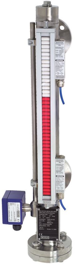
EN Operating instructions model BNA                               Page        3 - 18

DE Betriebsanleitung Typ BNA                                      Seite     19 - 33

   © 04/2015 WIKA Alexander Wiegand SE & Co. KG
   All rights reserved. / Alle Rechte vorbehalten.
   WIKA® and KSR® are registered trademarks in various countries.
   WIKA® und KSR® sind geschützte Marken in verschiedenen Ländern.

   Prior to starting any work, read the operating instructions!
   Keep for later use!

   Vor Beginn aller Arbeiten Betriebsanleitung lesen!
                                                                                         001958.03 03/2019 EN/DE

   Zum späteren Gebrauch aufbewahren!

    2                         Operating instructions bypass level indicator, model BNA
Contents
Contents EN
1. General information 4
2. Design and function 5
3. Safety 5
4. Transport, packaging and storage 10
5. Commissioning, operation 10
6. Faults 13
7. Maintenance and cleaning 14
8. Dismounting, return and disposal 15
9. Specifications 16
Declarations of conformity can be found online at www.wika.com.
001958.03 03/2019 EN/DE
Operating instructions bypass level indicator, model BNA 31. General information
1. General information
■■ The bypass level indicators described in the operating instructions
have been designed and manufactured using state-of-the-art
EN
technology. All components are subject to stringent quality and
environmental criteria during production. Our management systems
are certified to ISO 9001.
■■ These operating instructions contain important information on
handling the instrument. Working safely requires that all safety
instructions and work instructions are observed.
■■ Observe the relevant local accident prevention regulations and
general safety regulations for the instrument's range of use.
■■ The operating instructions are part of the product and must be kept
in the immediate vicinity of the instrument and readily accessible to
skilled personnel at any time. Pass the operating instructions onto the
next operator or owner of the instrument.
■■ Skilled personnel must have carefully read and understood the
operating instructions prior to beginning any work.
■■ The general terms and conditions contained in the sales
documentation shall apply.
■■ Subject to technical modifications.
■■ Further information:
- Internet address: www.wika.de / www.wika.com
- Relevant data sheet: LM 10.01
001958.03 03/2019 EN/DE
4 Operating instructions bypass level indicator, model BNA2. Design and function / 3. Safety
2. Design and function
2.1 Description
The bypass level indicators work according to the principle of
EN
communicating vessels. The bypass vessel contains a float with a built-in
permanent magnet. This changes its position depending on the level
of the medium. Magnetic indicators, switches and level sensors are
mounted to the outside of the bypass tube and actuated by the magnetic
field. Measurement of the level by guided wave radar is also possible.
The fitting of these options is carried out according to customer
specifiactions in the factory. The principle structure is described in chapter
5.3 “Commissioning”. Customer-specific versions are manufactured to order.
2.2 Scope of delivery
Cross-check scope of delivery with delivery note.
3. Safety
3.1 Explanation of symbols
DANGER!
... indicates a directly dangerous situation resulting in serious
injury or death, if not avoided.
WARNING!
... indicates a potentially dangerous situation that can result in
serious injury or death, if not avoided.
CAUTION!
... indicates a potentially dangerous situation that can result in
light injuries or damage to property or the environment, if not
avoided.
001958.03 03/2019 EN/DE
Operating instructions bypass level indicator, model BNA 53. Safety
Information
... points out useful tips, recommendations and information for
efficient and trouble-free operation.
EN
3.2 Intended use
The bypass level indicator serves for continuously measuring the level of
liquids in vessels.
The scope of application is defined by the technical performance limits
and materials.
■■ The liquids must not have any large contamination or coarse
particulates and must not have a tendency to crystallise. Ensure
that the wetted materials of the bypass level indicator are sufficiently
resistant to the medium being monitored. Not suitable for dispersions,
abrasive liquids, highly viscous media and colours.
■■ This instrument is not permitted to be used in hazardous areas! For
these areas, bypass level indicators with approval (e.g. in accordance
with ATEX) are required.
■■ The operating conditions specified in the operating instructions must
be observed.
■■ Do not operate the instrument in the direct vicinity of ferromagnetic
environments (min. distance 50 mm).
■■ Do not operate the instrument in the immediate vicinity of strong
electromagnetic fields or in the immediate vicinity of equipment that
can be affected by magnetic fields (min. clearance 1 m).
■■ The bypass level indicators must not be exposed to heavy
mechanical strain (impact, bending, vibration).
The instrument has been designed and built solely for the intended use
described here, and may only be used accordingly.
001958.03 03/2019 EN/DE
The manufacturer shall not be liable for claims of any type based on
operation contrary to the intended use.
6 Operating instructions bypass level indicator, model BNA3. Safety
DANGER!
Work on containers involves the danger of intoxication and
suffocation. No work is allowed to be carried out unless by
taking suitable personal protective measures (e.g. respiratory
protection apparatus, protective outfit etc.).
EN
3.3 Improper use
Improper use is defined as any application that exceeds the technical
performance limits or is not compatible with the materials.
WARNING!
Injuries through improper use
Improper use of the instrument can lead to hazardous
situations and injuries.
▶▶ Refrain from unauthorised modifications to the instrument.
▶▶ Do not use the instrument within hazardous areas.
Any use beyond or different to the intended use is considered as
improper use.
Do not use this instrument in safety or emergency stop devices.
3.4 Responsibility of the operator
The instrument is used in the industrial sector. The operator is therefore
responsible for legal obligations regarding safety at work.
The safety instructions within these operating instructions, as well as the
safety, accident prevention and environmental protection regulations for
the application area must be maintained.
To ensure safe working on the instrument, the operating company must
ensure the following:
■■ The operating personnel are regularly instructed in all topics
regarding work safety, first aid and environmental protection
and know the operating instructions and in particular, the safety
001958.03 03/2019 EN/DE
instructions contained therein.
■■ The operating personnel have read the operating instructions and
taken note of the safety instructions contained therein.
■■ The intended use for the application is complied with.
■■ Following testing, improper use of the instrument is excluded.
Operating instructions bypass level indicator, model BNA 73. Safety
3.5 Personnel qualification
WARNING!
Risk of injury should qualification be insufficient
EN Improper handling can result in considerable injury and
damage to equipment.
▶▶ The activities described in these operating instructions
may only be carried out by skilled personnel who have the
qualifications described below.
Skilled personnel
Skilled personnel, authorised by the operator, are understood to
be personnel who, based on their technical training, knowledge
of measurement and control technology and on their experience
and knowledge of country-specific regulations, current standards
and directives, are capable of carrying out the work described and
independently recognising potential hazards.
3.6 Personal protective equipment
The personal protective equipment is designed to protect the skilled
personnel from hazards that could impair their safety or health during
work. When carrying out the various tasks on and with the instrument,
the skilled personnel must wear personal protective equipment.
Follow the instructions displayed in the work area regarding
personal protective equipment!
The requisite personal protective equipment must be provided by the
operating company.
001958.03 03/2019 EN/DE
8 Operating instructions bypass level indicator, model BNA3. Safety
3.7 Labelling, safety marks
Product label (examples)
EN
Model specification
Material of bypass chamber
PS: Design pressure
PT: Test pressure
Permissible medium temperature range
Density of the medium
Float specification
Measuring point number
Serial number
001958.03 03/2019 EN/DE
Before mounting and commissioning the instrument, ensure
you read the operating instructions!
Operating instructions bypass level indicator, model BNA 94. Transport ... / 5. Commissioning, operation
4. Transport, packaging and storage
4.1 Transport
EN Check the bypass level indicator for any damage that may have been
caused by transport.
Obvious damage must be reported immediately.
4.2 Packaging and storage
Do not remove packaging until just before commissioning.
5. Commissioning, operation
■■ Observe all instructions given on the shipment packaging for
removing the transportation safety devices.
■■ Remove the bypass level indicator carefully from the packaging!
■■ When unpacking, check all components for any external damage.
5.1 Mounting preparation
■■ Detach the float attached to the bypass level indicator from the
bypass chamber and remove the transport sleeve.
■■ Remove the protection caps of the process connections.
■■ Ensure that the sealing faces of the vessel or bypass level indicator
are clean and do not show any mechanical damage.
■■ Check the connection dimensions (centre-to-centre distance) and the
alignment of the process connections on the vessel. 001958.03 03/2019 EN/DE
10 Operating instructions bypass level indicator, model BNA5. Commissioning, operation
Initialisation of magnetic display and magnetic switch
Slowly move the enclosed float from bottom to top on the magnetic
display and then back down again.
Align additionally mounted magnetic
switches on the basis of the same
EN
principle. For bypass level indicators
with insulation and magnetic displays
with Plexiglass attachments, the float
must be moved up and down inside
the tube.
For magnetic displays with purge
gas connections, these connections
must have an airtight seal. Please
refer in this case to the mounting and
operating instructions for magnetic
displays with purge gas connections
as well.
5.2 Mounting
■■ Observe the torque values of
screws specified in pipefitting work.
■■ Install the bypass level indicator
without tension.
■■ In the selection of the mounting
material (sealings, screws,
washers and nuts), take the
process conditions into account.
The suitability of the sealing must
be specified with regard to the
medium and its vapours.
001958.03 03/2019 EN/DE
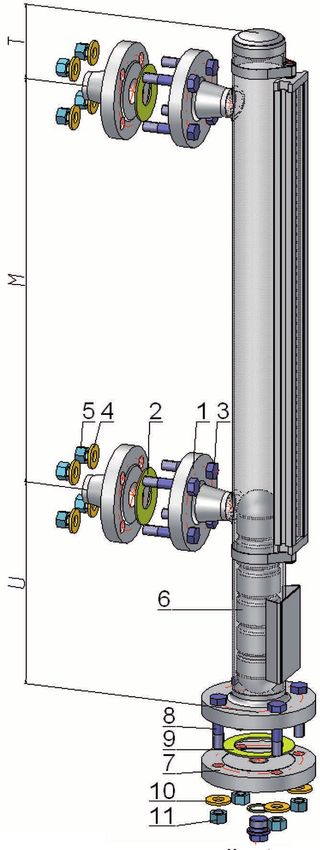
T = upper projection
M = centre-to-centre distance
U = lower projection
Operating instructions bypass level indicator, model BNA 115. Commissioning, operation
In addition, ensure it has corresponding corrosion resistance.
The bypass level indicator is mounted in a vertical position on the vessel
to be monitored using the process connections (1) provided. Seals
(2), screws (3), washers (4) and nuts (5) suitable for the process
EN connection must be used for mounting. If necessary, shut-off valves must
be mounted between the vessel and the bypass.
Installing the float
■■ Clean the float of anything stuck on it in the area of the float magnet
system
■■ Remove the bottom flange (7) and insert the float (6) into the tube
from the bottom (the marking “top” or a legible model code marks the
top side of the float)
■■ Place the seal (9) onto the bottom flange. Replace the bottom flange
and fix it in place using the screws (8)
5.3 Commissioning
If the bypass level indicator is fitted with shut-off valves between process
connections and tank, proceed as follows:
■■ Close drain and vent fittings on the bypass level indicator
■■ Slowly open the shut-off valve at the upper process connection
■■ Slowly open the shut-off valve at the lower process connection
As liquid flows into the bypass chamber, the float rises to the top.
The magnetic system turns the elements of the magnetic display
from “light” to “dark”. The current filling level is shown after liquid
equalisation between the vessel and the bypass level indicator.
■■ Always observe the mounting and operating instructions of
accessories before putting them into operation
Bypass level indicator with heating jacket
In this version, the bypass tube is surrounded by a second tube. Heated
liquid or vapour (heat carrier) can flow through this interspace via two
connections. The materials used must be designed for these conditions.
001958.03 03/2019 EN/DE
12 Operating instructions bypass level indicator, model BNA5. Commissioning, operation / 6. Faults
WARNING!
The heating jacket of the bypass level indicators may only be
used according to the specified maximum values for pressure
and temperature.
EN
Attachment of accessories to the bypass level indicator
For the mounting of accessories (e.g. BLR or BLM sensors or BGU
switches), the relevant maximum values for the instrument must be
considered. The applicable laws and directives for the assembly and the
planned purpose of application must be observed.
6. Faults
The following table contains the most frequent causes of
faults and the necessary countermeasures.
Faults Causes Measures
Bypass level The thread sizes or flange sizes Modification of the vessel
indicator cannot for the bypass level indicator do Return to the factory
be fitted at the not match
planned place on Thread on the screwed Rework the thread or
the vessel coupling on the vessel is faulty replace the screwed
coupling
Mounting thread on the bypass Return to the factory
level indicator is faulty
Centre-to-centre distance of Modification of the vessel
the vessel does not correlate
with the bypass level indicator Return to the factory
Process connections are not Modification of the vessel
attached parallel to one another
001958.03 03/2019 EN/DE
Operating instructions bypass level indicator, model BNA 136. Faults / 7. Maintenance and cleaning
CAUTION!
Physical injuries and damage to property and the
environment
If faults cannot be eliminated by means of the listed
EN measures, the instrument must be taken out of operation
immediately.
▶▶ Ensure that there is no longer any pressure present and
protect against being put into operation accidentally.
▶▶ Contact the manufacturer.
▶▶ If a return is needed, please follow the instructions given in
chapter 8.2 “Return”.
7. Maintenance and cleaning
7.1 Maintenance
When used properly, bypass level indicators work maintenance-free.
They must be subjected to visual inspection within the context of regular
maintenance, however, and included in the tank pressure test.
DANGER!
Work on containers involves the danger of intoxication and
suffocation. No work is allowed to be carried out unless by
taking suitable personal protective measures (e.g. respiratory
protection apparatus, protective outfit etc.).
Repairs must only be carried out by the manufacturer.
Perfect functioning of the bypass level indicator can only be
guaranteed when original accessories and spare parts are
used.
001958.03 03/2019 EN/DE
14 Operating instructions bypass level indicator, model BNA7. Maintenance and cleaning / 8. Dismounting ...
7.2 Cleaning
CAUTION!
Physical injuries and damage to property and the
environment EN
Improper cleaning may lead to physical injuries and damage
to property and the environment. Residual media in the
dismounted instrument can result in a risk to persons, the
environment and equipment.
▶▶ Rinse or clean the removed instrument.
▶▶ Sufficient precautionary measures must be taken.
1. Prior to cleaning, properly disconnect the instrument from the process
and the power supply.
2. Clean the instrument carefully with a moist cloth.
3. Electrical connections must not come into contact with moisture!
CAUTION!
Damage to property
Improper cleaning may lead to damage to the instrument!
▶▶ Do not use any aggressive cleaning agents.
▶▶ Do not use any pointed and hard objects for cleaning.
8. Dismounting, return and disposal
WARNING!
Physical injuries and damage to property and the
environment through residual media
Residual media in the dismounted instrument can result in a
risk to persons, the environment and equipment.
▶▶ Wash or clean the dismounted instrument, in order to
protect persons and the environment from exposure to
residual media.
001958.03 03/2019 EN/DE
8.1 Dismounting
Only disconnect the measuring instrument once the system has been
depressurised and the power disconnected!
Operating instructions bypass level indicator, model BNA 158. Dismounting, return and ... / 9. Specifications
8.2 Return
Wash or clean the dismounted bypass level indicator before returning
it, in order to protect personnel and the environment from exposure to
EN residual media.
Information on returns can be found under the heading
“Service” on our local website.
8.3 Disposal
Incorrect disposal can put the environment at risk.
Dispose of instrument components and packaging materials in an
environmentally compatible way and in accordance with the country-
specific waste disposal regulations.
9. Specifications
Bypass level Material Max. Max.
indicator pressure temperature
in bar in °C
Compact version, Stainless steel 1.4571 40 -196 ... +150
model BNA-C (316Ti)
Standard version, Stainless steel 1.4571 64 -196 ... +450
model BNA-S (316Ti), 1.4404 (316L),
1.4401/1.4404 (316/316L)
High-pressure Stainless steel 1.4571 400 -196 ... +450
version, (316Ti), 1.4404 (316L)
model BNA-H
Plastic version, PP, PVDF 6 -10 ... +100
model BNA-P
DUPlus version, Stainless steel 1.4571 64 -196 ... +450
standard, (316Ti), 1.4404 (316L),
001958.03 03/2019 EN/DE
model BNA-SD 1.4401/1.4404 (316/316L)
DUPlus version, Stainless steel 1.4571 160 -196 ... +450
high pressure, (316Ti), 1.4404 (316L),
model BNA-HD 1.4401/1.4404 (316/316L)
16 Operating instructions bypass level indicator, model BNA9. Specifications
Bypass level Material Max. Max.
indicator pressure temperature
in bar in °C
Liquid gas/ Stainless steel 1.4571 25 -60 ... +300 EN
KOPlus version, (316Ti), 1.4404 (316L)
model BNA-L
Special materials, Stainless steel 6Mo 1.4547 250 -196 ... +450
model BNA-X (UNS S31254)
Stainless steel 1.4571 16 depending on
(316Ti) with internal coating the medium
E-CTFE, ETFE or PTFE
Titanium 3.7035 64 -196 ... +450
Hastelloy C276 (2.4819) 160 -196 ... +450
Heating jacket Stainless steel 1.4571 64 -60 ... +450
version, model (316Ti), 1.4404 (316L)
BNA-J
001958.03 03/2019 EN/DE
Operating instructions bypass level indicator, model BNA 17EN
001958.03 03/2019 EN/DE
18 Operating instructions bypass level indicator, model BNAInhalt
Inhalt
DE
1. Allgemeines 20
2. Aufbau und Funktion 21
3. Sicherheit 21
4. Transport, Verpackung und Lagerung 26
5. Inbetriebnahme, Betrieb 26
6. Störungen 29
7. Wartung und Reinigung 30
8. Demontage, Rücksendung und Entsorgung 31
9. Technische Daten 32
Konformitätserklärungen finden Sie online unter www.wika.de.
001958.03 03/2019 EN/DE
Betriebsanleitung Bypass-Niveaustandsanzeiger, Typ BNA 191. Allgemeines
1. Allgemeines
■■ Die in der Betriebsanleitung beschriebenen Bypass-Niveaustands-
anzeiger werden nach dem aktuellen Stand der Technik konstruiert
und gefertigt. Alle Komponenten unterliegen während der Fertigung
strengen Qualitäts- und Umweltkriterien. Unsere Managementsyste-
DE me sind nach ISO 9001 zertifiziert.
■■ Diese Betriebsanleitung gibt wichtige Hinweise zum Umgang mit dem
Gerät. Voraussetzung für sicheres Arbeiten ist die Einhaltung aller
angegebenen Sicherheitshinweise und Handlungsanweisungen.
■■ Die für den Einsatzbereich des Gerätes geltenden örtlichen Unfall-
verhütungsvorschriften und allgemeinen Sicherheitsbestimmungen
einhalten.
■■ Die Betriebsanleitung ist Produktbestandteil und muss in unmittel-
barer Nähe des Gerätes für das Fachpersonal jederzeit zugänglich
aufbewahrt werden. Betriebsanleitung an nachfolgende Benutzer
oder Besitzer des Gerätes weitergeben.
■■ Das Fachpersonal muss die Betriebsanleitung vor Beginn aller Arbei-
ten sorgfältig durchgelesen und verstanden haben.
■■ Es gelten die allgemeinen Geschäftsbedingungen in den Verkaufs-
unterlagen.
■■ Technische Änderungen vorbehalten.
■■ Weitere Informationen:
- Internet-Adresse: www.wika.de / www.wika.com
- Zugehöriges Datenblatt: LM 10.01
001958.03 03/2019 EN/DE
20 Betriebsanleitung Bypass-Niveaustandsanzeiger, Typ BNA2. Aufbau und Funktion / 3. Sicherheit
2. Aufbau und Funktion
2.1 Beschreibung
Die Bypass-Niveaustandsanzeiger arbeiten nach dem Prinzip der
kommunizierenden Röhre. In der Bypasskammer befindet sich ein
Schwimmer mit eingebautem Permanentmagnet. Dieser ändert seine
Position abhängig vom Füllstand des Messstoffes. Durch das Magnetfeld DE
werden außen am Bypassrohr angebrachte Magnetanzeigen, Schalter
und Messwertgeber betätigt. Auch eine Messung des Füllstandes mit
geführtem Radar ist möglich.
Der Anbau bzw. Einbau dieser Optionen erfolgt kundenspezifisch
ab Werk. Der prinzipielle Aufbau ist im Kapitel 5.3 „Inbetriebnahme“
beschrieben. Kundenspezifische Ausführungen werden gemäß Auftrag
ausgeführt.
2.2 Lieferumfang
Lieferumfang mit dem Lieferschein abgleichen.
3. Sicherheit
3.1 Symbolerklärung
GEFAHR!
... weist auf eine unmittelbar gefährliche Situation hin, die
zum Tod oder zu schweren Verletzungen führt, wenn sie nicht
gemieden wird.
WARNUNG!
... weist auf eine möglicherweise gefährliche Situation hin, die
zum Tod oder zu schweren Verletzungen führen kann, wenn
sie nicht gemieden wird.
001958.03 03/2019 EN/DE
VORSICHT!
... weist auf eine möglicherweise gefährliche Situation hin, die
zu geringfügigen oder leichten Verletzungen bzw. Sach- und
Umweltschäden führen kann, wenn sie nicht gemieden wird.
Betriebsanleitung Bypass-Niveaustandsanzeiger, Typ BNA 213. Sicherheit
Information
... hebt nützliche Tipps und Empfehlungen sowie Informatio-
nen für einen effizienten und störungsfreien Betrieb hervor.
3.2 Bestimmungsgemäße Verwendung
Der Bypass-Niveaustandsanzeiger dient zur kontinuierlichen Füllstand-
DE messung von Flüssigkeiten in Behältern.
Der Einsatzbereich ergibt sich aus den technischen Leistungsgrenzen
und Werkstoffen.
■■ Die Flüssigkeiten dürfen keine starken Verschmutzungen oder
Grobteile aufweisen und nicht zum Auskristallisieren neigen. Es
ist sicherzustellen, dass die medienberührenden Werkstoffe des
Bypass-Niveaustandsanzeigers gegen das zu überwachende
Medium ausreichend beständig sind. Nicht geeignet für Dispersio-
nen, abrasive Flüssigkeiten, hochviskose Medien und Farben.
■■ Dieses Gerät ist nicht für den Einsatz in explosionsgefährdeten Berei-
chen zugelassen! Für diese Bereiche sind Bypass-Niveaustandsan-
zeiger mit Zulassung (z. B. nach ATEX) erforderlich.
■■ Die in der Betriebsanleitung angegebenen Einsatzbedingungen sind
einzuhalten.
■■ Gerät nicht in unmittelbarer Nähe von ferromagnetischer Umgebung
(Abstand min. 50 mm) betreiben.
■■ Gerät nicht in unmittelbarer Nähe von starken elektromagnetischen
Feldern bzw. in unmittelbarer Nähe von Einrichtungen betreiben, die
durch Magnetfelder beeinflusst werden können (Abstand min. 1 m).
■■ Die Bypass-Niveaustandsanzeiger dürfen keinen starken mecha-
nischen Belastungen (Stoß, Verbiegen, Vibrationen) ausgesetzt
werden.
Das Gerät ist ausschließlich für den hier beschriebenen bestimmungs-
001958.03 03/2019 EN/DE
gemäßen Verwendungszweck konzipiert und konstruiert und darf nur
dementsprechend verwendet werden.
Ansprüche jeglicher Art aufgrund von nicht bestimmungsgemäßer
Verwendung sind ausgeschlossen.
22 Betriebsanleitung Bypass-Niveaustandsanzeiger, Typ BNA3. Sicherheit
GEFAHR!
Beim Arbeiten an Behältern, besteht Vergiftungs- oder
Erstickungsgefahr. Arbeiten dürfen nur unter Anwendung
geeigneter Personenschutzmaßnahmen (z. B. Atemschutzge-
rät, Schutzkleidung o. Ä.). durchgeführt werden.
3.3 Fehlgebrauch DE
Als Fehlgebrauch gilt jede Verwendung, die die technischen Leistungs-
grenzen überschreitet oder mit den Werkstoffen unverträglich ist.
WARNUNG!
Verletzungen durch Fehlgebrauch
Fehlgebrauch des Gerätes kann zu gefährlichen Situationen
und Verletzungen führen.
▶▶ Eigenmächtige Umbauten am Gerät unterlassen.
▶▶ Gerät nicht in explosionsgefährdeten Bereichen einsetzen.
Jede über die bestimmungsgemäße Verwendung hinausgehende oder
andersartige Benutzung gilt als Fehlgebrauch.
Dieses Gerät nicht in Sicherheits- oder in Not-Aus-Einrichtungen benutzen.
3.4 Verantwortung des Betreibers
Das Gerät wird im gewerblichen Bereich eingesetzt. Der Betreiber unter-
liegt daher den gesetzlichen Pflichten zur Arbeitssicherheit.
Die Sicherheitshinweise dieser Betriebsanleitung, sowie die für den
Einsatzbereich des Gerätes gültigen Sicherheits-, Unfallverhütungs- und
Umweltschutzvorschriften einhalten.
Für ein sicheres Arbeiten am Gerät muss der Betreiber Folgendes
sicherstellen:
■■ Bedienpersonal wird regelmäßig in allen zutreffenden Fragen von
Arbeitssicherheit, Erste Hilfe und Umweltschutz unterwiesen.
001958.03 03/2019 EN/DE
■■ Bedienpersonal hat Betriebsanleitung gelesen und insbesondere die
darin enthaltenen Sicherheitshinweise zur Kenntnis genommen.
■■ Die bestimmungsgemäße Verwendung für den Anwendungsfall wird
eingehalten.
■■ Nach Prüfung ist ein Fehlgebrauch des Gerätes ausgeschlossen.
Betriebsanleitung Bypass-Niveaustandsanzeiger, Typ BNA 233. Sicherheit
3.5 Personalqualifikation
WARNUNG!
Verletzungsgefahr bei unzureichender Qualifikation
Unsachgemäßer Umgang kann zu erheblichen Personen-
und Sachschäden führen.
DE ▶▶ Die in dieser Betriebsanleitung beschriebenen Tätigkei-
ten nur durch Fachpersonal nachfolgend beschriebener
Qualifikation durchführen lassen.
Fachpersonal
Das vom Betreiber autorisierte Fachpersonal ist aufgrund seiner
fachlichen Ausbildung, seiner Kenntnisse der Mess- und Regelungs-
technik und seiner Erfahrungen sowie Kenntnis der landesspezifi-
schen Vorschriften, geltenden Normen und Richtlinien in der Lage, die
beschriebenen Arbeiten auszuführen und mögliche Gefahren selbststän-
dig zu erkennen.
3.6 Persönliche Schutzausrüstung
Die persönliche Schutzausrüstung dient dazu, das Fachpersonal gegen
Gefahren zu schützen, die dessen Sicherheit oder Gesundheit bei der
Arbeit beeinträchtigen könnten. Beim Ausführen der verschiedenen
Arbeiten an und mit dem Gerät muss das Fachpersonal persönliche
Schutzausrüstung tragen.
Im Arbeitsbereich angebrachte Hinweise zur persönlichen Schutz-
ausrüstung befolgen!
Die erforderliche persönliche Schutzausrüstung muss vom Betreiber zur
Verfügung gestellt werden.
001958.03 03/2019 EN/DE
24 Betriebsanleitung Bypass-Niveaustandsanzeiger, Typ BNA3. Sicherheit
3.7 Beschilderung, Sicherheitskennzeichnungen
Typenschild (Beispiele)
DE
Typ-Spezifikation
Werkstoff Bypasskammer
PS: Auslegungsdruck
PT: Prüfdruck
Zulässiger Messstofftemperaturbereich
Dichte des Messstoffes
Schwimmer-Spezifikation
Messstellennummer
Seriennummer
001958.03 03/2019 EN/DE
Vor Montage und Inbetriebnahme des Gerätes unbedingt die
Betriebsanleitung lesen!
Betriebsanleitung Bypass-Niveaustandsanzeiger, Typ BNA 254. Transport ... / 5. Inbetriebnahme, Betrieb
4. Transport, Verpackung und Lagerung
4.1 Transport
Bypass-Niveaustandsanzeiger auf eventuell vorhandene Transportschä-
den untersuchen.
Offensichtliche Schäden unverzüglich mitteilen.
DE
4.2 Verpackung und Lagerung
Verpackung erst unmittelbar vor der Inbetriebnahme entfernen.
5. Inbetriebnahme, Betrieb
■■ Alle auf der Versandverpackung angegebenen Hinweise zum Entfer-
nen der Transportsicherungen beachten.
■■ Den Bypass-Niveaustandsanzeiger vorsichtig aus der Verpackung
entnehmen!
■■ Beim Auspacken alle Teile auf äußerliche Beschädigungen überprü-
fen.
5.1 Montagevorbereitung
■■ Den am Bypass-Niveaustandsanzeiger befestigten Schwimmer vom
Bypassgefäß abnehmen und die Transporthülse entfernen.
■■ Die Schutzkappen der Prozessanschlüsse entfernen.
■■ Sicherstellen, das die Dichtflächen des Behälters bzw. des Bypass-
Niveaustandsanzeigers sauber sind und keine mechanische Beschä-
digung aufweisen.
■■ Anschlussmaße (Mittenabstand) und Flucht der Prozessanschlüsse
am Behälter prüfen.
001958.03 03/2019 EN/DE
26 Betriebsanleitung Bypass-Niveaustandsanzeiger, Typ BNA5. Inbetriebnahme, Betrieb
Initialisierung Magnetanzeige und Magnetschalter
Beigefügten Schwimmer auf der Magnetanzeige langsam von unten
nach oben und anschließend wieder
nach unten bewegen.
Zusätzlich angebaute Magnetschalter
nach dem gleichen Prinzip ausrichten.
Für Bypass-Niveaustandsanzeiger mit DE
Isolierung oder Magnetanzeigen mit
Acrylglasvorsatz muss der Schwimmer
im Inneren des Rohres auf und ab
bewegt werden.
Bei Magnetanzeigen mit Spülgas-
anschlüssen sind diese luftdicht zu
verschließen. Bitte beachten Sie hierzu
auch die Montage- und Betriebsanlei-
tung der Magnetanzeige mit Spülgas-
anschlüssen.
5.2 Montage
■■ Die im Rohrleitungsbau vorge-
schriebenen Drehmomentwerte der
Schrauben einhalten.
■■ Bypass-Niveaustandsanzeiger
spannungsfrei einbauen.
■■ Bei der Auswahl des Montagema-
terials (Dichtungen, Schrauben,
Unterlegscheiben und Muttern) die
Prozessbedingungen beachten.
Die Eignung der Dichtung muss
hinsichtlich Messstoff, und dessen
Dämpfen gegeben sein.
001958.03 03/2019 EN/DE
T = oberer Überstand
M = Mittenabstand
U = unterer Überstand
Betriebsanleitung Bypass-Niveaustandsanzeiger, Typ BNA 275. Inbetriebnahme, Betrieb
Zusätzlich ist auf entsprechende Korrosionsbeständigkeit zu achten.
Der Bypass-Niveaustandsanzeiger wird mittels der vorgesehenen
Prozessanschlüsse (1), in einer vertikalen Position, an den zu überwa-
chenden Behälter montiert. Zur Montage sind zum Prozessanschluss
passende Dichtungen (2), Schrauben (3), Unterlegscheiben (4) und
Muttern (5) zu verwenden. Bei Bedarf sind Absperrarmaturen zwischen
DE Behälter und Bypass zu montieren.
Einbau des Schwimmers
■■ Den Schwimmer von eventuell anhaftenden Teilen im Bereich des
Schwimmermagnetsystems reinigen
■■ Bodenflansch (7) abnehmen und Schwimmer (6) von unten in
das Rohr einführen (Beschriftung „top“ bzw. ein lesbarer Typcode
kennzeichnen die Oberseite des Schwimmers)
■■ Dichtung (9) auf den Bodenflansch auflegen. Bodenflansch wieder
aufsetzen und mittels Schrauben (8) befestigen
5.3 Inbetriebnahme
Sofern der Bypass-Niveaustandsanzeiger mit Absperrventilen zwischen
Prozessanschlüssen und Behälter ausgerüstet ist, wie folgt vorgehen:
■■ Ablass- und Entlüftungseinrichtungen am Bypass-Niveaustandsan-
zeiger schließen
■■ Absperrventil am oberen Prozessanschluss langsam öffnen
■■ Absperrventil am unteren Prozessanschluss langsam öffnen.
Mit der einströmenden Flüssigkeit ins Bypassgefäß schwimmt der
Schwimmer auf. Das Magnetsystem dreht die Elemente der Magene-
tanzeige von der „hellen zur „dunklen“ Seite. Nach dem Flüssigkeits-
ausgleich zwischen Behälter und Bypass-Niveaustandsanzeiger wird
der aktuelle Füllstand angezeigt.
■■ Zur Inbetriebnahme von Zubehör unbedingt die jeweilige
Montage- und Betriebsanleitung beachten
Bypass-Niveaustandsanzeiger mit Heizmantel
001958.03 03/2019 EN/DE
Bei dieser Ausführung ist das Bypassrohr mit einem zweiten Rohr
umgeben. Der so gebildete Zwischenraum kann über zwei Anschlüsse
von einer erhitzten Flüssigkeit oder Dampf (Wärmeträger) durchströmt
werden. Die verwendeten Werkstoffe müssen für diese Bedingungen
ausgelegt sein.
28 Betriebsanleitung Bypass-Niveaustandsanzeiger, Typ BNA5. Inbetriebnahme, Betrieb / 6. Störungen
WARNUNG!
Der Heizmantel der Bypass-Niveaustandsanzeiger darf nur
entsprechend den angegebenen Maximalwerten für Druck
und Temperatur eingesetzt werden.
Anbau von Zubehör an den Bypass-Niveaustandsanzeiger
Beim Anbau von Zubehör (z. B. Messwertgeber BLR, BLM oder Schalter DE
BGU) sind die jeweiligen Höchstwerte des Gerätes zu beachten. Die
für den Zusammenbau und den Einsatzzweck gültigen Gesetze und
Richtlinien sind einzuhalten.
6. Störungen
In der folgenden Tabelle sind die häufigsten Fehlerursachen
und erforderliche Gegenmaßnahmen aufgeführt.
Störungen Ursachen Maßnahmen
Bypass-Niveau- Gewindegrößen oder Flansch- Umbau des Behälters
standsanzeiger größen des Bypass-Niveau- Rücksendung ans Werk
lässt sich nicht an standsanzeiger stimmen nicht
der vorgesehenen überein
Stelle am Behälter Gewinde der Befestigungsmuf- Nacharbeiten des Gewin-
anbauen fe am Behälter defekt des oder Austauschen
der Befestigungsmuffe
Einschraubgewinde am Rücksendung ans Werk
Bypass-Niveaustandsanzeiger
defekt
Mittenabstand des Behälters Umbau des Behälters
stimmt nicht mit dem des
Bypass-Niveaustandsanzeiger Rücksendung ans Werk
überein
001958.03 03/2019 EN/DE
Prozessanschlüsse sind nicht Umbau des Behälters
parallel zueinander angebracht
Betriebsanleitung Bypass-Niveaustandsanzeiger, Typ BNA 296. Störungen / 7. Wartung und Reinigung
VORSICHT!
Körperverletzungen, Sach- und Umweltschäden
Können Störungen mit Hilfe der aufgeführten Maßnahmen
nicht beseitigt werden, Gerät unverzüglich außer Betrieb
setzen.
▶▶ Sicherstellen, dass kein Druck mehr anliegt und gegen
DE versehentliche Inbetriebnahme schützen.
▶▶ Kontakt mit dem Hersteller aufnehmen.
▶▶ Bei notwendiger Rücksendung die Hinweise unter Kapitel
8.2 „Rücksendung“ beachten.
7. Wartung und Reinigung
7.1 Wartung
Die Bypass-Niveaustandsanzeiger arbeiten bei bestimmungsgemäßem
Gebrauch wartungsfrei. Sie sind jedoch im Rahmen der regelmäßigen
Wartung einer Sichtkontrolle zu unterziehen und in die Druckprüfung des
Behälters mit einzubeziehen.
GEFAHR!
Beim Arbeiten an Behältern, besteht Vergiftungs- oder
Erstickungsgefahr. Arbeiten dürfen nur unter Anwendung
geeigneter Personenschutzmaßnahmen (z. B. Atemschutzge-
rät, Schutzkleidung o. Ä.). durchgeführt werden.
Reparaturen sind ausschließlich vom Hersteller durchzuführen.
Die Funktion der Bypass-Niveaustandsanzeiger kann nur bei
Verwendung von Originalzubehör und Ersatzteilen gewähr-
leistet werden.
001958.03 03/2019 EN/DE
30 Betriebsanleitung Bypass-Niveaustandsanzeiger, Typ BNA7. Wartung und Reinigung / 8. Demontage ...
7.2 Reinigung
VORSICHT!
Körperverletzungen, Sach- und Umweltschäden
Eine unsachgemäße Reinigung führt zu Körperverletzungen,
Sach- und Umweltschäden. Messstoffreste im ausgebauten
Gerät können zur Gefährdung von Personen, Umwelt und
DE
Einrichtung führen.
▶▶ Ausgebautes Gerät spülen bzw. säubern.
▶▶ Ausreichende Vorsichtsmaßnahmen sind zu ergreifen.
1. Vor der Reinigung das Gerät ordnungsgemäß vom Prozess und der
Stromversorgung trennen.
2. Das Gerät vorsichtig mit einem feuchten Tuch reinigen.
3. Elektrische Anschlüsse nicht mit Feuchtigkeit in Berührung bringen!
VORSICHT!
Sachbeschädigung
Eine unsachgemäße Reinigung führt zur Beschädigung des
Gerätes!
▶▶ Keine aggressiven Reinigungmittel verwenden.
▶▶ Keine harten und spitzen Gegenstände zur Reinigung
verwenden.
8. Demontage, Rücksendung und Entsorgung
WARNUNG!
Körperverletzungen, Sach- und Umweltschäden durch
Messstoffreste
Messstoffreste im ausgebauten Gerät können zur Gefähr-
dung von Personen, Umwelt und Einrichtung führen.
▶▶ Ausgebautes Gerät spülen bzw. säubern, um Personen
und Umwelt vor Gefährdung durch anhaftende Messstoff-
001958.03 03/2019 EN/DE
reste zu schützen.
8.1 Demontage
Messgerät nur im drucklosen und spannungsfreiem Zustand demontie-
ren!
Betriebsanleitung Bypass-Niveaustandsanzeiger, Typ BNA 318. Demontage ... / 9. Technische Daten
8.2 Rücksendung
Ausgebauten Bypass-Niveaustandsanzeiger vor der Rücksendung
spülen bzw. säubern, um Mitarbeiter und Umwelt vor Gefährdung durch
anhaftende Messstoffreste zu schützen.
Hinweise zur Rücksendung befinden sich in der Rubrik
DE „Service“ auf unserer lokalen Internetseite.
8.3 Entsorgung
Durch falsche Entsorgung können Gefahren für die Umwelt entstehen.
Gerätekomponenten und Verpackungsmaterialien entsprechend den
landesspezifischen Abfallbehandlungs- und Entsorgungsvorschriften
umweltgerecht entsorgen.
9. Technische Daten
Bypass- Werkstoff Max. Max. Tem-
Niveaustands- Druck peratur
anzeiger in bar in °C
Kompaktausfüh- CrNi-Stahl 1.4571 (316Ti) 40 -196 ... +150
rung, Typ BNA-C
Standardausfüh- CrNi-Stahl 1.4571 (316Ti), 1.4404 64 -196 ... +450
rung, Typ BNA-S (316L), 1.4401/1.4404 (316/316L)
Hochdruckaus- CrNi-Stahl 1.4571 (316Ti), 1.4404 400 -196 ... +450
führung, (316L)
Typ BNA-H
Kunststoff- PP, PVDF 6 -10 ... +100
ausführung,
Typ BNA-P
DUPlus-Ausfüh- CrNi-Stahl 1.4571 (316Ti), 1.4404 64 -196 ... +450
rung, Standard, (316L), 1.4401/1.4404 (316/316L)
001958.03 03/2019 EN/DE
Typ BNA-SD
DUPlus- CrNi-Stahl 1.4571 (316Ti), 1.4404 160 -196 ... +450
Ausführung, (316L), 1.4401/1.4404 (316/316L)
Hochdruck,
Typ BNA-HD
32 Betriebsanleitung Bypass-Niveaustandsanzeiger, Typ BNA9. Technische Daten
Bypass- Werkstoff Max. Max. Tem-
Niveaustands- Druck peratur
anzeiger in bar in °C
Flüssiggas-/ CrNi-Stahl 1.4571 (316Ti), 1.4404 25 -60 ... +300
KOPlus-Ausfüh- (316L)
rung, Typ BNA-L
Sonderwerkstof- CrNi-Stahl 6Mo 1.4547 (UNS 250 -196 ... +450 DE
fe, Typ BNA-X S31254)
CrNi-Stahl 1.4571 (316Ti) mit 16 abhängig vom
Innenbeschichtung E-CTFE, ETFE Messstoff
oder PTFE
Titan 3.7035 64 -196 ... +450
Hastelloy C276 (2.4819) 160 -196 ... +450
Heizmantelaus- CrNi-Stahl 1.4571 (316Ti), 1.4404 64 -60 ... +450
führung, Typ (316L)
BNA-J
001958.03 03/2019 EN/DE
Betriebsanleitung Bypass-Niveaustandsanzeiger, Typ BNA 33001958.03 03/2019 EN/DE 34 Operating instructions bypass level indicator, model BNA
001958.03 03/2019 EN/DE

                          Operating instructions bypass level indicator, model BNA   35
KSR Kuebler subsidiaries worldwide can be found online at www.ksr-kuebler.com.
WIKA subsidiaries worldwide can be found online at www.wika.com.
Manufacturer contact: Sales contact:
A division of the WIKA group
KSR Kuebler Niveau-Messtechnik AG WIKA Alexander Wiegand SE & Co. KG
Heinrich-Kuebler-Platz 1 Alexander-Wiegand-Strasse 30
69439 Zwingenberg am Neckar • Germany 63911 Klingenberg • Germany
001958.03 03/2019 EN/DE
Tel. +49 6263/87-0 Tel. +49 9372 132-0
Fax +49 6263/87-99 Fax +49 9372 132-406
info@ksr-kuebler.com info@wika.de
www.ksr-kuebler.com www.wika.de
36 Operating instructions bypass level indicator, model BNAYou can also read