Digital Stopwatch Timer Circuit Using 555timer and CD4033 - ijirset
←
→
Page content transcription
If your browser does not render page correctly, please read the page content below
ISSN (Online) : 2319 - 8753
ISSN (Print) : 2347 - 6710
International Journal of Innovative Research in Science, Engineering and Technology
An ISO 3297: 2007 Certified Organization Volume 7, Special Issue 1, March 2018
6th National Conference on Frontiers in Communication and Signal Processing Systems (NCFCSPS '18)
13th-14th March 2018
Organized by
Department of ECE, Adhiyamaan College of Engineering, Hosur, Tamilnadu, India
Digital Stopwatch Timer Circuit Using
555timer and CD4033
Kokila.C1, Kousalya.J.R2, Madhumitha.K3, Nandhini.P4 and Mr.Martin Joel Ratnam5
UG Scholar, Department of ECE, Adhiyamaan College of Engineering, Hosur, TN, India1,2,3,4
Associate Professor, Department of ECE, Adhiyamaan College of Engineering, Hosur, TN, India5
ABSTRACT: Stopwatches find use as time keeping devices in many fields, namely sports. Stopwatches may be
analog or digital. Digital stopwatches are much more common the analog version owing to their higher accuracy
and ease of use. Here we have tried to realize a digital stopwatch of reasonable accuracy and reliability.Here we
design the second type wherein the circuit displays count from 0 to 59, representing a 60 second time interval. In
other words here the circuit displays the time in seconds only. This is a simple circuit consisting of a 555 timer
to produce the clock pulses and two counter ICs to carry out the counting operation.
I. INTRODUCTION
In this circuit we have used a 555 timer IC based astable multi-vibrator which is for creating 1 second delay.
And two common cathode seven segment decoder IC’s namely CD4033. The output of astablemultivibrator is
directly applied to seven segment decoder IC’s (U4) Clock pin (1) and carry output pin(5) of U4 IC is directly
connected to clock pin (1) of second seven segment decoder(U3). And two seven segment are connected with
these decoder (U3 and U4).
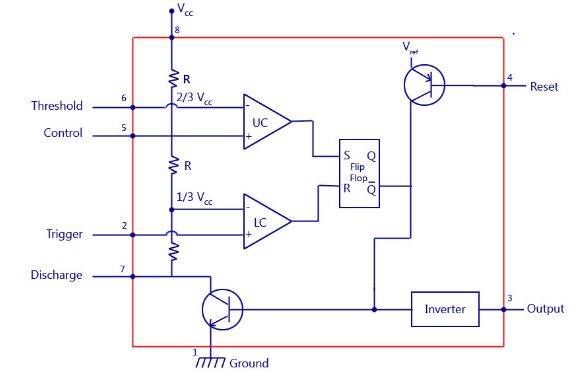
II. IC 555 TIMER WORKING
The 555 timer IC is an integral part of electronics projects. Be it a simple project involving a single 8 bit micro-
controller and some peripherals or a complex one involving system on chips (SoCs), 555 timer working is
involved. These provide time delays, as an oscillator and as a flip-flop element among other applications.
Introduced in 1971 by the American company Signetics, the 555 is still in widespread use due to its low price,
ease of use and stability. It is made by many companies in the original bipolar and low-power CMOS types.
Depending on the manufacturer, the standard 555 package includes 25 transistors, 2 diodes and 15 resistors on a
silicon chip installed in an 8-pin mini dual-in-line package (DIP-8). Variants consists of combining multiple
chips on one board. However 555 is still the most popular. Let’s look at the pin diagram to have an idea about
the timer IC before we talk about 555 timer working.
Copyright to IJIRSET www.ijirset.com 290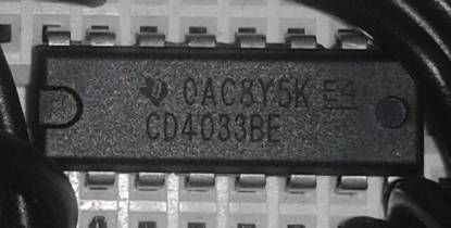
ISSN (Online) : 2319 - 8753
ISSN (Print) : 2347 - 6710
International Journal of Innovative Research in Science, Engineering and Technology
An ISO 3297: 2007 Certified Organization Volume 7, Special Issue 1, March 2018
6th National Conference on Frontiers in Communication and Signal Processing Systems (NCFCSPS '18)
13th-14th March 2018
Organized by
Department of ECE, Adhiyamaan College of Engineering, Hosur, Tamilnadu, India
Fig 1: Circuit Diagram
III. FEATURES OF THE 555 TIMER
555 is used in almost every electronic circuit today. For a 555 timer working as a flip flop or as a multi-vibrator,
it has a particular set of configurations. Some of the major features of the 555 would be,
It operates from a wide range of power ranging from +5 Volts to +18 Volts supply voltage.
Sinking or sourcing 200 mA of load current.
The duty cycle of the timer is adjustable.
Also, the maximum power dissipation per package is 600 mW and its trigger and reset inputs has
logic compatibility.
IV. SEVEN SEGMENT DISPLAY
Seven segment display is the most common device used for displaying digits and alphabet. One can see a device
in TV shows counting down to ‘0’, these are nothing but seven segments. Use of LEDs in seven segment
displays made it more popular.
Liquid crystal displays (LCD) use the properties of liquid crystal for displaying. LCD will not emit the light
directly.These LED’s or LCD are used to display the required numeral or alphabet. Single seven segment or
number of segments arranged in an order meets our requirements.
Copyright to IJIRSET www.ijirset.com 291ISSN (Online) : 2319 - 8753
ISSN (Print) : 2347 - 6710
International Journal of Innovative Research in Science, Engineering and Technology
An ISO 3297: 2007 Certified Organization Volume 7, Special Issue 1, March 2018
6th National Conference on Frontiers in Communication and Signal Processing Systems (NCFCSPS '18)
13th-14th March 2018
Organized by
Department of ECE, Adhiyamaan College of Engineering, Hosur, Tamilnadu, India
V. WORKING OF SEVEN SEGMENT DISPLAY
Seven segment display works, by glowing the required respective LEDS in the numeral. The display is
controlled using pins that are left freely. Forward biasing of these pins in a sequence will display the particular
numeral or alphabet. Depending on the type of seven segment the segment pins are applied with logic high or
logic zero and in the similar way to the common pins also.
For example to display numeral ‘1’ segments b and c are to be switched on and the remaining segments are
required to be switched off. In order to display two digits two seven segments are used.
Generally, in LED package either all the cathodes or all anodes of the segments are combined to form a
common pin. Thus each seven segment display will have seven pins used for displaying the digits, one common
pin and another pin for decimal/dot point
Bottom view of the seven segment display is shown below. The bottom view of the segment shows 10 pins of
the segment. These are cathode or anode pins of the LEDs present in the seven segment. Seven segment is
illuminated using these pins.
VI. CD4033 WORKING
CD4033 is a Johnson counterIC commonly used in digital display. It has a 5 stage Johnson decade counter with
decoder which convert the Johnson code to a 7 segment decoded output.
Advantage of this IC is it can be operated at high voltage of 20V. But is highly sensitive, can detect emf present
in the atmosphere and is sensitive to static charge also It can be used in various application like in 7 segment
decimal display circuit, in clocks, timer etc. To understand its working first have a look on its pin diagram.
Copyright to IJIRSET www.ijirset.com 292ISSN (Online) : 2319 - 8753
ISSN (Print) : 2347 - 6710
International Journal of Innovative Research in Science, Engineering and Technology
An ISO 3297: 2007 Certified Organization Volume 7, Special Issue 1, March 2018
6th National Conference on Frontiers in Communication and Signal Processing Systems (NCFCSPS '18)
13th-14th March 2018
Organized by
Department of ECE, Adhiyamaan College of Engineering, Hosur, Tamilnadu, India
This is counter and seven segment decoding in one package IC which is very easy to interface with seven
segment displays. This is fully static counter operational IC and ideal for low power displays. This IC can be
used for decade counting seven segment decimal displays, frequency division seven segment decimal displays,
clocks, watches, timers, counter/display driver for meter applications.
VII. INTERFACING CD4033 WITH THE TIMER IC
In the following circuit we have used a 555 timer in astable oscillator mode to provide clock signal to input of
IC CD4033 to start its counting which can be display on 7 segment display. Here reset switch is used to reset the
counting any time needed by the user.
Now you can perform different experiments and play around this IC like you can add LDR so that it will start its
counter when shadow falls on it or you can cascade two or more CD4033 to make timer circuits etc. So start
building your own circuit.
VIII. RESULT AND DISCUSSIONS
After completion of this digital stopwatch project I have learnt some knowledge in designing the circuit and
understood the implementation using 555timer and Johnson counter.The circuit has been implemented on bread
board and soldiered on general purpose PCB.This circuit can operate in two modes with play and pause
switches.Laid emphasis compact design.Calibration process yielded combined “coarse & fine” delay of one ms.
Copyright to IJIRSET www.ijirset.com 293ISSN (Online) : 2319 - 8753
ISSN (Print) : 2347 - 6710
International Journal of Innovative Research in Science, Engineering and Technology
An ISO 3297: 2007 Certified Organization Volume 7, Special Issue 1, March 2018
6th National Conference on Frontiers in Communication and Signal Processing Systems (NCFCSPS '18)
13th-14th March 2018
Organized by
Department of ECE, Adhiyamaan College of Engineering, Hosur, Tamilnadu, India
REFERENCES
1.International organization for standardization(ISO). International vocabulary of basic and general terms in meterology(VIM),1993.
2.ISO/IEC 17025,general requirements for the competence of testing and calibration laboraties. International organization for
standardization(ISO),2000.
3.Anderson, R.J., and G.L.Harris.”specification an tolerances for field stanar stopwatches”. Natl.inst.stand.techno handbook 105-
5,october1997.
4.Robbins, michale.”Electronic clocks and watches”.Indianpolis:Howarw.sams co.,1975.
5.Vig, J.R.”Introduction to quartz frequency standards”.Army research an development technical report,SLCET-TR-92-1,October 1992
Copyright to IJIRSET www.ijirset.com 294You can also read


