DN3PD2 Original Instruction Manual - Safety switchgear to monitor the speed of three-phase and single-phase motors without sensor - DINA Elektronik
←
→
Page content transcription
If your browser does not render page correctly, please read the page content below
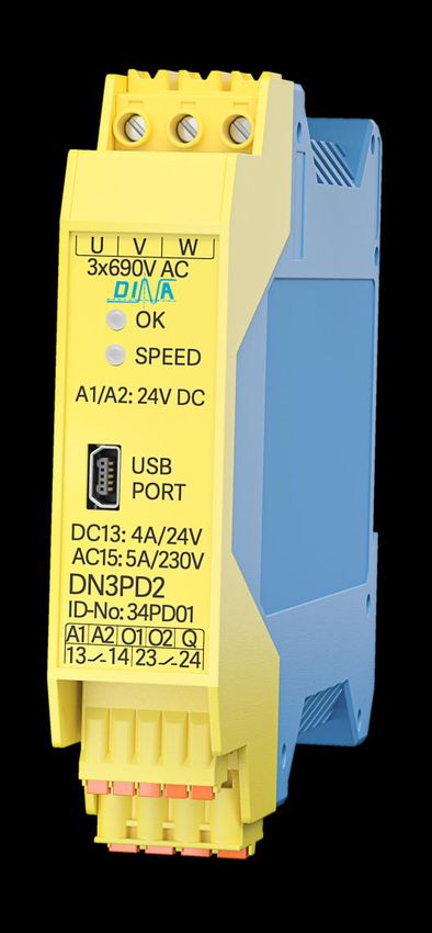
DN3PD2
                                   Original Instruction Manual

Safety switchgear
to monitor the speed of three-phase and
single-phase motors without
sensor

with
Configuration-Software GO:BEYOND

                                                   wir sind sicherheit.

EG-Konformitätserklärung
EC-Declaration of Conformity
Hersteller/manufacturer
DINA Elektronik GmbH
Esslinger Str. 84
72649 Wolfschlugen
Germany

Wir erklären, dass folgendes Produkt allen einschlägigen Bestimmungen der EG-Richtlinien entspricht.
We declare that the following product complies with all relevant provisions of the EC directives.
Produkt/product                                                    Beschreibung/description
DN3PD2                                                             Sicherheitsschaltgerät zur sensorlosen Drehzahlüberwachung
                                                                   bei Drei- und Einphasen Motoren
                                                                   Safety switchgear unit to monitor the speed of 3-phases and
                                                                   single phase motors without sensor

EG-Richtlinien/EC-directives                                     Angewandte Normen/Applied standards
2006/42/EG EG-Maschinenrichtlinie/Machinery-Directive            EN ISO 13849-1:2015
2014/30/EU EMV-Richtlinie/EMC-Directive                          IEC 62061:2005 + AC:2010 + A1:2013 + A2:2015
2011/65/EU RoHS Richtlinie/RoHS-Directive                        IEC 61800-5-2:2016
                                                                 IEC 61508: Parts 1-7:2010
                                                                 IEC 60947-5-1:2016
                                                                 EN 60204-1:2018
                                                                 EN 61326-1 :2013
                                                                 EN 61326-3-1:2017

                                                                 GS-ET-20: 2016-10 (Zusatzanforderung)

                                                                 EG Baumusterprüfbescheinigung/EC Type-Examination certifi-
Notifizierte Stelle/notified Body
                                                                 cate
TÜV Rheinland Industrie Service GmbH                             Reg.-Nr./No.: 01/205/5759.00/20
Am Grauen Stein
51105 Köln
Germany

NB 0035

Dokumentationsbeauftragter/authorised representative.
DINA Elektronik GmbH
Esslinger Str. 84
72649 Wolfschlugen
Germany

Wolfschlugen, 01.06.2020

Stefan Najib (Geschaftsführer/CEO)

21-06-09 / 34pd01-V0815                                                                                                          3
DN3PD2
Inhaltsverzeichnis
Content
1 Intended Use 7
Approvals 7
Safety parameters 7
Ordering data 7
2 Safety regulations 8
3 Important information and validation 8
4 Function description 9
Speed monitoring 9
Acknowledge function 9
Start-up monitoring 9
4.3.1. Functional diagram with start-up monitoring 10
4.3.2. Functional diagram without start-up monitoring 10
Switch-off delay 11
Switch-on delay 11
Advanced settings 11
Minimum switch-off time 12
Password 12
Validation 12
Display 12
Diagnosis 13
Signal outputs 13
USB interface 13
Connections 14
Block diagram 14
5 Applications 15
Motor with frequency converter 15
Motor with star-delta circuit 15
Single-phase motor 15
Servo motor 15
6 Mounting and removal 16
Wiring notes 16
7 Configuration 17
System requirements 17
Installation the Configurations-Software 17
Connection to the PC 17
User interface 18
Parameterization 18
Machine data 20
Read out the project 20
Create a project 20
Edit and Change password 20
Diagnosis 21
Validation 23
4 21-06-09 / 34pd01-V0815DN3PD2
Inhaltsverzeichnis
8 Errors: reporting and rectification 24
LED-flash-codes 24
9 Example of application 24
10 Technical data 26
Ambient conditions 26
Input data 26
Output data 26
General data 26
Connection data 27
Relay load curve 27
11 Dimensions 27
21-06-09 / 34pd01-V0815 5DN3PD2
Always read the additional applicable online documentation before working on/with the safety switchgear.
Make sure you always work with the valid documentation. This is available online at
http://www.dina.de/downloads/
Dispose of the device according to the national environmental regulations.
Symbol and Notes:
WARNING
This symbol indicates hazards that could lead to personal injury.
CAUTION
This symbol warns of actions that could lead to property damage or malfunction.
Here you will find additional information or further sources of information.
Version overview / Change history
Version Date valid for ID-No Innovations / changes
0815 2020-06-16 34PD01
0815 2021-06-09 34PD01 Limitation when using servo motors
6 21-06-09 / 34pd01-V0815DN3PD2
Intended Use
1 Intended Use
DN3PD2 is a safety switchgear to monitor the speed of three-phase and single-phase motors without sensor.
It detects or monitors a minimum speed, a maximum speed or a speed range.
The unit meets Cat. 4/ PL e acc. to ISO 13849-1, SIL (CL) 3 acc. to IEC 62061 and IEC 61508.
It can be used in safety current circuit according to VDE 0113 T.1
The safety switchgear is configured using the configuration software GO:BEYOND.
Approvals
Safety parameters
The unit meets Cat. 4/ PL e and SIL (CL) 3.
Utilization categories PFHd [h] MTTFd [a] DCavg
6A DC1 2 cycles/h 5,38 x 10⁻⁹ 441 99%
4A DC13 2 cycles /h 1,33 x 10⁻⁸ 198 99%
6A AC1 2 cycles /h 1,87 x 10⁻⁸ 153 99%
5A AC15 2 cycles /h 1,87 x 10⁻⁸ 153 99%
Ordering data
Description Type ID-No.:
Speed monitoring, sensorless 0-1200Hz, 2 contact outputs, USB interface DN3PD2 34PD01
21-06-09 / 34pd01-V0815 7DN3PD2
Safety regulations
2 Safety regulations
The device may only be installed and commissioned by an electrician or trained persons who are familiar with these
operating instructions and the applicable regulations regarding work safety and accident prevention.
Observe the VDE, EN and local regulations, particularly with respect to the protective measures.
Failure to observe the regulations may result in death, severe bodily injury or extensive property damage.
For emergency-stop applications, either the integrated function for restart interlock must be used or automatic re-
starting of the machine must be prevented by means of a higher-level control.
During transport, storage and operation, adhere to the conditions specified in EN 60068-2-1, 2-2!
Unauthorized modifications shall render any warranty null and void. Dangers may thereby arise that could result in
severe injuries or even death.
Install the device in a control cabinet with a protection class of at least IP54! Dust and moisture may otherwise re-
sult in impaired functions. Installation in a control cabinet is mandatory.
Ensure adequate protection circuits at output contacts for capacitive and inductive loads!
The device is to be installed taking into account the distances required per DIN EN 50274, VDE 0660-514.
During operation, switching devices carry dangerous voltage. Do not remove protective covers.
Replace the device after the first malfunction.
Properly dispose of the device at the end of its service life.
If these regulations are not adhered to or in the event of improper use, DINA Elektronik GmbH accepts absolutely
no liability for the resulting property damages or personal injury.
Save this product information!
3 Important information and validation
The product described here was developed to perform safety-related functions as part of a complete system.
The complete system consists of sensors, evaluation and message units as well as concepts for safe shutdowns.
It is the responsibility of the manufacturer of a system or machine to ensure the proper overall function.
The manufacturer of the system is required to test and to document the effectiveness of the implemented safety
concept within the complete system.
In this case, it must be checked whether the release contacts open when exceeding or falling below the thresholds.
This verification is to be performed after every modification to the safety concept or to safety parameters.
DINA Elektronik is not in the position to guarantee the properties of a complete system that was not designed by
DINA.
DINA Elektronik GmbH also accepts no liability for recommendations that are given or implied by the following de-
scription.
No new guarantee, warranty or liability claims that extend beyond DINA's general delivery conditions can be de-
rived on the basis of the following description.
To avoid EMC disturbances, the physical environmental and operating conditions at the installation location of the
product must comply with section EMC of DIN EN 60204-1.
When using contact outputs, the safety function must be requested once a day at PL e and once a year at PL d ac-
cording to IEC 61800-5-2.
Observe the general technical data at the end of this operating manual.
8 21-06-09 / 34pd01-V0815DN3PD2
Function description
4 Function description
The two-channel evaluation unit of the safety switchgear module measures the frequency of the effective rotating field of
the motor at the measuring terminals L1, L2, L3.
If the parameterized switching threshold frequencies are exceeded or undershot (fmin and fmax), or an internal or external
fault exists, the enabling current paths 13/14, 23/24 open immediately. The device is in safe switching state.
The device has a standard USB connection. The configuration software enables a parameterization and online monitoring.
After applying the operating voltage (24 V DC) to terminals A1 and A2, the safety relay will operate a self-test. The safety
relay is in safe condition for the duration of the self-test. All enable current paths are open.
After a successful self-test, the device is ready for operation. The LED OK lights up green.
Speed monitoring
The parameters fmax (maximum frequency) and fmin (minimum frequency) define the speed limits of the motor. The limit
frequencies fmax and fmin are calculated from the speed n and the number of pole pairs:
f [Hz]= (n [U/min] / 60) x number of pole pairs
Example: 5000 rev /min x 3 (number of pole pairs) / 60 = 250Hz
Asynchronous motors have a load-dependent slip between the motor speed and the rotating field frequency. This must be
observed by the configuration of the switching threshold (fmin and fmax).
CAUTION
Note that the method of frequency measurement does not recognize a mechanically blocked motor or an over-
loaded motor!
The following monitoring functions are possible:
- Monitoring only at maximum speed
- Monitoring of a speed range with startup monitoring
- Monitoring of a speed range without startup monitoring
fmin: minimum frequency
If fmin is undershot, the output contacts (13-14 / 23-24) switch off.
They switch on again after the acknowledgment via the acknowledgment input Q.
Depending on the acknowledgment mode, the switch-on-conditions differ. Please note the chapter "Startup monitoring". If
fmin = 0 there is no monitoring to a minimum speed. The output contacts remain closed at standstill.
fmax: maximum frequency
If fmax is exceeded, the output contacts (13-14 / 23-24) switch off.
They switch on again after the acknowledgment via the acknowledgment input Q, if fmax (minus hysteresis) is undershot.
CAUTION
Note that a coasting motor is detected either as a standstill (if fmin = 0, no switch-off) or underrun (if fmin> 0,
switch-off).
Acknowledge function
The acknowledgment function allows the module to be reset to operational readiness after a shutdown due to under- or
overspeed. The reset takes place via the input Q at the module, if none of the mentioned states is present.
Automatic or manual acknowledgment is possible. With automatic acknowledgment, the Q input must always be connected
to 24V DC.
A manual acknowledgment takes place after a falling signal edge at the input Q (tQ ≥ 200ms and ≤ 10s).
Start-up monitoring
The startup monitoring time tA is a time limit within which the actual speed must be greater than fmin. If the minimum
speed is not reached during this time, the enable current path opens again.
The start-up monitoring time is parameterized (0s to 60s). It is not retriggerable, it cannot be restarted while it is running.
The start-up monitoring time starts
In case of manual acknowledgment: with the falling edge of the acknowledge signal
21-06-09 / 34pd01-V0815 9DN3PD2
Function description
In case of automatic acknowledgment: if the actual speed is> 1Hz
In the acknowledgment mode without startup monitoring (0s), the outputs only switch on within the permitted range.
4.3.1. Functional diagram with start-up monitoring
Automatic acknowledgement Manual acknowledgement
(fmin must be at least 1,1Hz !)
f f
fmax fmax
Hyst eresis Hyst eresis
Hyst eresis Hyst eresis
fmin fmin
1 Hz
0,5 Hz
tA tA >t min 1Hz 1 Start-up monitoring time starts with the falling edge
of the acknowledgement signal.
2 Start-up monitoring time is expired. Enabling cur- 2 Start-up monitoring time is expired. Enabling current
rent path remains closed because f>fmin. path remains closed because f>fmin.
3 Enabling current path opens because fDN3PD2
Function description
Switch-off delay
Optionally, you can set a switch-off delay tV from 0s to 2s for the enable current path. The switch-off delay time starts if a
speed limit is reached. During this time, the enable contacts remain closed and the "SPEED" LED flashes. When the switch-
off delay time is expired, the enable current path opens.
If the speed reaches the target range during the switch-off delay time, the contacts remain closed and the switch-off delay
time is reset.
CAUTION
Note that changing the switch-off delay affects the reaction time of the safety function!
The switch-off delay time is not started when the shutdown occurs due to an internal or external fault.
Switch-on delay
Optionally, you can set a switch-on delay tE from 0s to 10s for the enable current path. The switch-on delay time starts, if the
frequency is in range and the acknowledgement is done. During this time, the enable contacts remain open and the
"SPEED" LED flashes.
When the switch-on delay time is expired, the enable current path closes.
f
fmax
Hyst eresis
Hyst eresis
fmin
t
tE tV tE tV tE
13/ 14, 23/ 24
Q-man
tE tV tE tV tE
13/ 14, 23/ 24
Q-aut o
t E = swit ch-on delay t V = swit ch-off delay
If you have also selected the "Start-up monitoring" function, the outputs only switch on after the switch-on delay time has
expired. Only then is the start-up monitoring active.
Advanced settings
Application dependent disturbances (e.g., vibrations or frequency overshoots) can adversely affect the measurement pro-
cess. This can lead to unintentional shutdowns. To ensure availability in the case of faulty applications, you can adjust the
parameters
Number of measuring cycles
Measurement sensitivity
Number of measuring cycles
In the settings “measuring accuracy” you set the number of measuring cycles to detect the movement. The parameter de-
termines with how many measurements the measured value is formed before it is switched off.
This multiple measurement has no influence on the switch-on behavior. Switching on takes place after one measuring cycle.
Default setting: 3 measuring cycles at frequencies > 30Hz
Maximum number of measuring cycles: 4
21-06-09 / 34pd01-V0815 11DN3PD2
Function description
CAUTION
The set factor is multiplied by the measuring time of the system and influences the reaction time of the safety
relay.
Few measuring cycles = short reaction time due to fast measuring value formation, but more prone to external disturbances
One measuring cycle = fastest reaction time
Many measuring cycles = long system reaction time but robust measurement
You can change the number of measuring cycles in the configuration software. You also define from which frequency this
number should be valid.
Below this frequency, a single measurement is always used.
Sensitivity
Change these parameters only after consultation with the DINA Elektronik GmbH service.
Minimum switch-off time
The minimum switch-off time tmin is the time that the enable current path is at least open after triggering before it switches
on again. It is 0.5s.
Password
The transfer of the parameters and the validation function can be password protected. The password can contain a maxi-
mum of 8 characters.
Validation
To validate the safety function, a validation tool is available in the configuration software.
With this function, the limit values fmax and fmin are reduced or increased by 10%, 20% or 30%, thereby forcing a switch-
off.
The validation requires the entry of the device password.
Note that validation displays the actual frequency, not the actual speed.
The relation actual frequency to speed (taking into account the number of poles and the gear factor) may have to
be additionally validated.
Display
The safety switchgear indicates its operational readiness and the status of the enabling current path by the two-color LEDs
"OK" and "SPEED". See table 4-1.
The red flashing LED "OK" indicates an error.
The green flashing LED "SPEED" indicates the expiry of a time constant.
LED OK LED SPEED Flash-code 13/14, 23/24 Status
green green - ON acknowledged in range
green OFF - OFF not acknowledged out of range
green flashing green 2 acknowledged, out of range
ON
start-up monitoring active
green flashing green 3 acknowledged,
ON out of range
off delay active
green flashing green 4 acknowledged, in range
OFF
on delay active
green OFF - OFF not acknowledged in range
flashing red OFF 1 OFF error See error table
red red - OFF device defect
table 4-1
12 21-06-09 / 34pd01-V0815DN3PD2
Function description
U V W
≤ 3x690V AC 1
OK 1s
pause
1s
pause
SPEED
U V W 2
≤ 3x690V AC
start-up monitoring
OK
SPEED 3
switch-off delay
4
switch-on delay
Diagnosis
In conjunction with the configuration software, diagnostics offers the following functions:
Reading out values from the safety switchgear during operation
Reading out data which are relevant for switch-off
Signal outputs
You can use the signal outputs O1 and O2 to control e.c. a non-safety PLC or signal units.
The message outputs have the following properties:
- digital
- potential-bound
- short circuit and overload protection
- not safety-related
The output O1 indicates the state of the enabling current path.
The output O2 indicates the operational readiness. This switches off in case of an error.
USB interface
Via the USB connection you connect the safety s to the PC (standard USB 2.0). You need the PC connection for the following
actions:
Transfer the configuration data
Read out the configuration to open it in the configuration software as a project and edit it if necessary.
Diagnosis
Validation
21-06-09 / 34pd01-V0815 13DN3PD2
Function description
Connections
U, V, W Measuring inputs are to be connected directly to the motor, without switching
contacts between
A1 Power supply +24V DC
A2 Power supply 0V
Q Acknowledgment input can be parameterized, manually or automatically
O1, O2 Digital positive switching semiconductor outputs for the transmission of switching
states to a higher-level control for diagnostic tasks.
13-14/23-24 Enabling contacts (2 NO-contacts). These switch off immediately if the parame-
terized speeds are undershot or exceeded or internal or external errors.
13/14, 23/24 are to be used in such a way that the intended safety function, e.g.
emergency stop is executed.
USB Port Mini-USB for connection at PC
OK-LED operational readiness
SPEED-LED state of the enabling current path
Block diagram
14 21-06-09 / 34pd01-V0815DN3PD2
Applications
5 Applications
Motor with frequency converter L1
L2
L3
The operation on electric power drive systems with adjustable speed
is possible. (Frequency converter) FU/ FC
CAUTION
Please note, that the DN3PD2 is not suitable for use U DN3PD2
V
on thyristor inverters. W
U1 V 1 W1
M
3
Motor with star-delta circuit L1L2 L3
Operation on motors with star-delta connection or pole changeover U1 V 1 W1
is possible. For pole-changing motors, please note that DN3PD2
detects the frequency and not the speed!
M U
V
DN3PD2
3 W
The measuring inputs U and W are bridged and directly connected to
W1 on the motor. U2 V 2 W2
The measuring input V is directly connected to W2 on the motor.
Single-phase motor L
N
Operation on a single-phase motor is possible.
The measuring inputs U and W are bridged and directly connected to
U1 on the motor.
The measuring input V is directly connected to U2 on the motor. U DN3PD2
V
W
U1 U2
M
1
Servo motor
WARNING
Applications with servomotors are possible to a limit extent.
Folgende Punkte sind zu beachten:
Operation must be limited to a maximum of 480 V AC.
The measurement sensitivity should be set to mode 4.
With the measurement sensitivity modes 1 to 3 there is a risk of an unknown wire break and a poten-
tially dangerous detection of a standstill.
The following test must be carried out before using the DN3PD2:
When the motor is running with a motor frequency of less than 2.5 Hz, terminal W on the module
must be disconnected.
If the enabling current path closes in this case, the module is not suitable for use on this motor.
21-06-09 / 34pd01-V0815 15DN3PD2
Mounting and removal
6 Mounting and removal
Mount the safety relay on a 35 mm DIN rail according to EN 60715.
Maintain the required distances according to DIN EN 50274, VDE 0660-514.
Avoid strong magnetic fields near the installation. (Magnetic field strength 32V DC destroy the device. Only use power supplies that generate a maximum of 32V in the event of
a fault.
16 21-06-09 / 34pd01-V0815DN3PD2
Configuration
7 Configuration
The configuration of the DN3PD2 safety switchgear is made via the configuration software GO:BEYOND.
The parameterization of the DN3PD2 is described in the following chapters.
WARNING: Danger through incorrectly set parameters
Incorrectly set parameters for motion monitoring can lead to dangerous machine or system states.
Make sure that the parameters entered or selected in the software correspond to the connected hard-
ware.
Carry out a function test after parameterization and after every change in the parameterization as part
of the validation.
Assistance during validation and commissioning can be a separate measuring device or the diagnostic function
(display of actual and limit values) in conjunction with the validation function in the configuration software.
The diagnostic function is not safety-related.
System requirements
The configuration software is compatible with the following operating systems
MS Windows 8
MS Windows 10
Hard disk space min. 1 GB
Main memory min. 2 GB
Resolution 1920 x 1080 px
Scaling 100%
Interface USB
Installation the Configurations-Software
The configuration software can be found in the download area of the article at dina.de/downloads/software.
Always work with the latest version of the software.
Installation of the software:
1. Download the software.
2. Start the installation.
3. Follow the instructions of the installation wizard.
4. Choose the language about “Settings” in the start screen.
Connection to the PC
Communication between the safety switchgear and the configuration software takes place via the USB interface.
Connect the safety relay to the PC using a suitable connection cable.
21-06-09 / 34pd01-V0815 17DN3PD2
Configuration
The interface is suitable for standard USB cables.
User interface
The configuration software has the following user interface.
Navigationsbereich Editor- und Aktionsbereich
Navigation area
In the navigation area you can select the following areas:
Parameterization edit parameters, password management
Diagnostics display of online values, error messages, switch-off-relevant data, device ID, valida-
tion
Interface selection of the interface
File new creation / saving / opening / printing / closing a project
Settings display of the working directory
Help help-menu
Edit- and Action area
This area offers the following functions:
Edit parameters
Read out the parameter from the switch gear to the configuration-software
Transmit the parameter from the configuration-software to the switch gear
Help
Parameterization
You can make the following settings on the configuration software
Parameter Range Note
COM-Port
18 21-06-09 / 34pd01-V0815DN3PD2
Configuration
Parameter Range Note
Password maximum 8 signs
fmax *) 0.5 - 1200 Hz
fmin *) 0.5 - 1200 Hz Minimum speed monitoring can
be deselected.
Acknowledgment - manual Automatic acknowledgment with
- automatic start-up monitoring:
fmin ≥ 1.1 Hz
Start-up monitoring 0-60s 0 ≙ only range-monitoring
Switch-off delay 0-2s
Switch-on delay 0-10s
Project name maximum 8 signs absolutely necessary
Author Is not transferred to the device.
Date mm.dd.yy
Advanced settings
Measurement accuracy
Number of measuring cycles 1-4
Frequency threshold 16 steps
Measurement sensitivity mode 1-4
Machine data
Axis type Linear axis, spindle, rotary axis
Number of pole pairs 1-99
Ratio 0.01-99999
Radius 1-9999
Pitch 0.001-9999
Max. speed Depending on the machine data
Min. speed and the permitted maximum
frequency.
*)
To determine the switching thresholds, the number of pole pairs must be taken into account:
f [Hz]= (n [U/min] / 60) x number of pole pairs
Example: 5000 rev/min x 3 (number of pole pairs) / 60 = 250Hz
Asynchronous motors have a load-dependent slip between the motor speed and the rotating field frequency. This
must be taken into account when parameterizing the threshold frequencies (fmin and fmax).
21-06-09 / 34pd01-V0815 19DN3PD2
Configuration
Machine data
The "Machine data" calculation tool can be used to determine fmin and fmax.
Enter the machine-specific data and the tool calculates the associated frequencies. The machine data can be saved in the
device. Check the checkbox "Take over machine data". Then it is no longer possible to enter the frequencies directly in the
"Parameterization" menu.
Read out the project
You can read out the parameterization saved on the safety relay.
No password is required for reading out.
Start the configuration software
Open the "Interface" menu item and select the COM port.
Open the "Parameterization" menu item.
Click the "Read out device" button.
Create a project
Start the configuration software.
Open the "Interface" menu item and select the COM port.
Open the "Parameterization" menu item.
Edit the parameter.
Transmit the project to the device with the button „save on device“.
There is always a password prompt. If no password is saved, confirm the query with "ok".
Confirm the settings
Save the project
Edit and Change password
Protect your safety relay against unauthorized access with a device password.
Open the menu item "Parameterization password"
Enter the current password. If no password is assigned, the field can remain empty.
Edit a new password and confirm it.
Click the button “save on device”.
The password is now stored in the device and must be specified when transferring a new project or when validation.
20 21-06-09 / 34pd01-V0815DN3PD2
Configuration
Diagnosis
The diagnosis offers the following functions:
1 Diagnosis start / stop Start or stop the diagnosis
2 Movement/time diagram For visual representation of the movement:
blue line: actual frequency
red lines: fmin and fmax
3 Status display of the input and output 13/14, 23/24: Status of the enabling current path
O1: Status the output O1
O2: Status the output O2
Q: Status of the input Q
4 Help and error list Help texts and occurred errors
5 Latch Data Read out switch-off relevant data
- Actual frequency
- States of the outputs/input
- advanced mode for service
6 Device ID Hardware and Firmware information
7 Validation See chapter „Validation“
1
4
2
3
21-06-09 / 34pd01-V0815 21DN3PD2
Configuration
5
6
22 21-06-09 / 34pd01-V0815DN3PD2
Configuration
Validation
Select the validation step
If the device is password-protected, you will be asked to enter a valid password.
The states are recorded and can be printed out as a protocol.
The validation level is automatically reset after 10s.
Press the “Stop Validation” button to stop recording
Alternatively, you can use the “auto. Start “. The validation levels are run through step by step and reset again. The auto-
matic validation stops automatically.
21-06-09 / 34pd01-V0815 23DN3PD2
Errors: reporting and rectification
8 Errors: reporting and rectification
The safety switchgear shows diagnosed errors that lead to the safe state of the device, as follows:
Flash-codes of the LED „OK“ on the device.
Error message in the software
LED-flash-codes
The safety relay displays error messages using LED flashing codes.
The blink code is repeated continuously with a pause of 1 s.
The meaning of the individual LED blink codes can be found in Fehler! Verweisquelle konnte nicht gefunden werden..
Example:
3 x flash / 1 s break / 3 x flash / 1 s break ...
That means error no. 3.
U V W
≤ 3x690V AC
OK 1s
Pause
1s
Pause
SPEED
Error-no. LED-flash-code Meaning / diagnostic information from Remedy
the software
1 1 x flash incorrect power supply Check power supply
UB = 20.5V-26,5V DC
2 2 x flash transmission error parameter Check
interface
connection cable
Have the parameters been con-
firmed before transfer?
3 3 x flash incorrect acknowledge signal Check the wiring at input Q for cross or short
at input Q circuits.
For manual acknowledgment:
Check whether the start signal is within the
time range of min. 200ms to max. 10s.
4 4 x flash open-circuit on U, V, W Check the wiring at the measuring inputs for
short circuit
cross-connection
wire break
5 5 x flash transmission error password The password was not confirmed. Transfer
the password again.
6 6 x flash Relay error Send the device to DINA Elektronik for test-
ing.
7 7 x flash single-channel error Check the wiring at the measuring inputs for
The signals at the measuring inputs are short circuit
different cross-connection
wire break
8 8 x flash Frequency > 1500Hz Check the frequency at the measuring inputs
9 9 x flash internal error Send the device to DINA Elektronik for test-
ing.
10 10 x flash internal error Send the device to DINA Elektronik for test-
ing.
Table 8-1
9 Example of application
24 21-06-09 / 34pd01-V0815DN3PD2
Example of application
Output contacts connected in parallel Output contacts connected in series
L1 24V DC
L2 L1 24V DC
L3 L2
L3
FU/ FC
14 FU/ FC 23
24 A1 Q 13 23
23 A1 Q 13 23
U
V DN3PD2
U
W V DN3PD2
U1 V 1 W1
W
M A2 O1 O2 14 24
14 24
U1 V 1 W1
NC
3 M A2 O1 O2 14 24
3 NC
0V
0V
21-06-09 / 34pd01-V0815 25DN3PD2
Technical data
10 Technical data
Ambient conditions
Ambient temperature (operation) -20 to +55°C
Ambient temperature (storage) -40 to +85°C
Maximum altitude < 2000m above sea level
Shock 15g
Vibration 10–150Hz, 1g
Input data
Operating voltage UB 24V DC -15 % / +10 %, reverse protection
Current draw at 24V DC typ. 80mA
Current draw at U, V, W 0,35mA at 690V AC
Input voltage at U, V, W 90 to 690V AC
Max. frequency at U, V, W 1200Hz
Minimum-PWM 2kHz
Measurement uncertainty 1%
Switching hysteresis 10%
Power consumption at A1/ A2 typ. 1,9W
Status display 2 x LED 2-color
Protection wiring Overvoltage/ inverse polarity protection
Acknowledgment input Q 24V digital
Output data
Relay outputs: enabling current path
Contact type 2 enabling NO-contacts
Contact material AgSnO2
Operating voltage 24V DC / 230V AC
Minimum switching current 3 mA/ 24V DC
Maximum switching current 6A / 24V DC/ 230V AC
Short-circuit strength 1000A SCPD 6A gL/gG
Mechanical life 107 switching cycles
Switch-off time Number of measuring cycles x (period (reciprocal value of the set frequency) +
max. 2ms cycle time) + max 10ms relay switch-on time
Output fuse 6 A gL/gG
B10d values acc. to AC15: 5A/230V AC, >2x10⁵, DC13: 4A/24V DC, >3x10⁵
5
DIN EN 61810-2-1, 01.2012 AC1: 6A/230V AC, >2x10 DC1: 6A/ 24V DC, >7x10⁶ switching cycles
Total current 13-14 and 23-24 with parallel connection: 6A with serial connection: 3A
Signal outputs
Number of outputs 2 (non-safety, digital outputs O1, O2)
Current ≤ 100mA, shot-circuit and overload protection
Voltage UB-1V
General data
Nominal operating mode 100 %
Degree of protection IP20
Degree of protection of inst. location closed cabinet, minimum IP54
Mounting position vertical or horizontal
Air and creepage distances DIN EN 50178
Rated insulation voltage 400V AC
Rated surge voltage / insulation Basic insulation 6kV:
between all current paths and housing
Safe insulation, reinforced insulation 8kV:
between U, V, W and USB interface
between U, V, W and A1, A2, O1, O2, Q
between U, V, W and 13/14, 23/24
Degree of pollution 2
Overvoltage category III
Housing material/ Type Polyamide PA not increased/ ME/ Fa. Phoenix Contact
Dimensions B x H x T/ 22,5 x 114 x 111 mm
26 21-06-09 / 34pd01-V0815DN3PD2
Dimensions
Connection data
Terminals/ Material Push-in, pluggable/ PA Screw, pluggable /PA
Number of positions 4 5 3
Conductor cross-section, flexible 0,25 - 2,5mm2 0,25 - 1,5mm2 0,25 - 2,5mm2
with wire end sleeve
Conductor cross section AWG 24…12 24…16 24…12
Connection wire 60/75°C copper
Tightening torque min/max 0,5Nm/0,6Nm
Relay load curve
Ohmic and inductive load for the enabling NO-contacts 13/14 und 23/24
1 ohmic load L/R = 0ms
2 inductive load L/R = 40ms
WARNING
Loads with high capacitive component can destroy the output contacts because the switching current is very
high.
11 Dimensions
111 22.5
114
21-06-09 / 34pd01-V0815 27wir sind sicherheit. DINA Elektronik GmbH Esslinger Str. 84 D72649 Wolfschlugen Phone +49 7022 95170 Fax +49 7022 9517700 info@dina.de www.dina.de
You can also read