EarthquakE pronE buildings - Wellington City Council guide
←
→
Page content transcription
If your browser does not render page correctly, please read the page content below
Wellington City Council guide

EarthquakE
pronE buildings
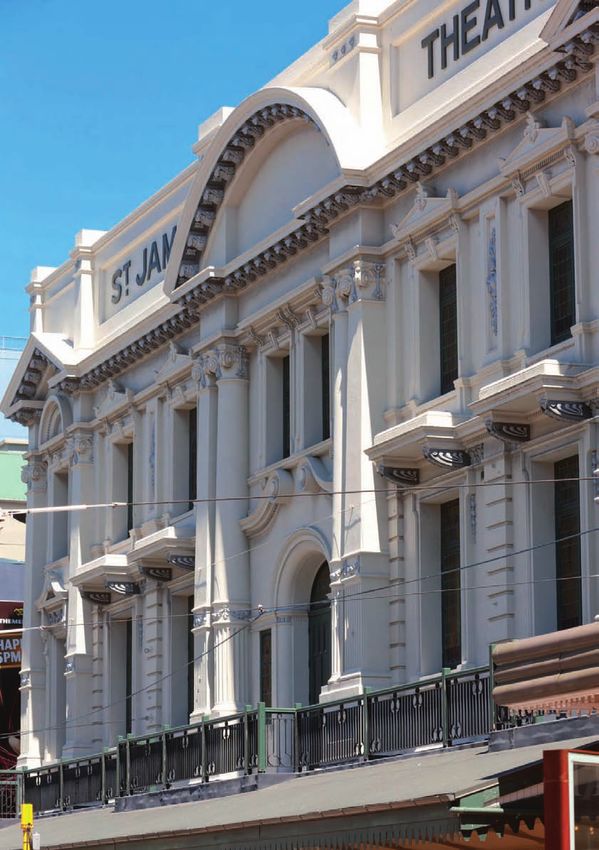
Wellington’s historic St James Theatre is a steel-frame and masonry
building dating from 1912. It was strengthened in the late 1990s as
part of a major refurbishment.

INTRODUCTION                                                                        4
1.0 NATIONAL SEISMICITY                                                             5
2.0 WELLINGTON                                                                      8
         2.1 POLICY AND SCOPE                                                      11
         2.2 ASSESSMENT                                                            12
         2.3 NOTIFICATION AND REPORTING                                            13
         2.4 RESOLUTION                                                            14
         2.5 HERITAGE                                                              15
         2.6 SUPPORT                                                               15
3.0 STRUCTURAL PERFORMANCE                                                         17
         3.1 ELEMENTS OF CONCERN                                                   17
         3.2 SEISMIC RETROFIT SOLUTIONS                                            18
4.0 FAQS AND MISCONCEPTIONS                                                        27
5.0 FURTHER INFORMATION                                                            29
6.0 GLOSSARY OF TERMS                                                              30
ACKNOWLEDGEMENTS                                                                   32
APPENDIX                                                                           33
References to products, brands or trade names are provided as examples only.
Wellington City Council does not endorse or confirm compliance of these products
with the New Zealand Building Code.

                       EARTHQUAKE PRONE BUILDINGS – WCC GUIDE                3
InTRODUcTIOn

New Zealand is situated on the Pacific Rim of Fire, straddling a          AIM OF THE GUIDE
major fault between the Australasian and Pacific tectonic plates -
                                                                          Since the devastating earthquakes that struck Canterbury in
meaning we are prone to earthquakes. All areas of New Zealand are
                                                                          2010/2011, public interest in how buildings perform during quakes
at some risk from a quake.
                                                                          has sharply increased. This guide aims to explain why and how
In recognition of this fact, national legislation has been changed to     Wellington City Council plans improve the seismic performance of
enhance our ability to cope with earthquakes, and the Building Act        earthquake-prone buildings in the city.
2004 introduced the requirement for all local councils to develop
and implement a specific policy on earthquake-prone, dangerous            WHO SHOULD READ THIS GUIDE?
and insanitary buildings.
                                                                          These days, it is no longer just seismic engineers who consider
The policies relating to earthquake-prone buildings (EPBs) are            these issues. Many members of the public want to know which
intended to determine how the assessment of a local council’s             buildings are safe to enter or occupy. Building owners are keen
buildings and private building stock will be carried out and in what      to understand what cost-effective techniques they can best use
priority order, strengthening requirements for any non-compliant          to make their buildings more resilient and therefore attractive for
buildings and the timeframes these buildings will need to be              tenants and the visiting members of the public.
made compliant.
                                                                          If you are a building owner, tenant, agent or engineer and you
Requirements on the heritage buildings – those buildings that             have an interest in why the Council is assessing buildings for their
individually or as a cluster form part of a region’s cultural heritage.   seismic performance and need for seismic retrofitting, this guide
To obtain the best possible result, the authority and the community       is for you. This is not, however, intended as a comprehensive
must strike a balance between the need for public safety, heritage        guide – so for further information we recommend you refer to our
preservation and cost minimisation.                                       Earthquake-Prone Building Policy on Wellington.govt.nz

                                                                          THIS GUIDE AIMS TO
                                                                          ExpLAIn WHy AnD HOW
                                                                          WELLInGTOn cITy cOUncIL
                         SAFETy         CoST                              pLAnS TO IMpROvE THE
                                                                          SEISMIc pERFORMAncE
                               hERITAgE                                   OF EARTHqUAkE-pROnE
                                                                          bUILDInGS In THE cITy.

    4       EARTHQUAKE PRONE BUILDINGS – WCC GUIDE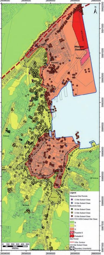
1.0
nATIOnAL SEISMICITy
New Zealand sits across the margin between the Australasian and Earthquakes have not constituted a major hazard to life and property
Pacific tectonic plates, which are moving relative to each other by in New Zealand when compared with many other seismically
about 40mm each year. In the North Island, the plates converge with active regions, or if we consider earthquakes in relation to other
each other and the Pacific Plate is subducted under (driven beneath) types of accident. The great Hawke’s Bay earthquake of 1931
the Australasian Plate. In the lower South Island, the opposite occurs resulted directly or indirectly in 255 deaths; a further 214 deaths
and it is the Australasian Plate that is being subducted. In the upper from earthquakes have been recorded as due to other earthquakes
South Island and Cook Strait area, the two plates slide past each since the year 1848. This number includes those who died in the
other in what is termed a strike-slip relationship. Christchurch earthquakes. It is therefore sensible and prudent that
various precautions are taken against the effects of possible future
As the plates move against each other, tension in the earth gradually
earthquakes. Organisations ready to deal with earthquake and other
builds up before eventually being released as earthquakes.
kinds of disaster are sponsored in the main centres of population by
Imperceptible seismic activity occurs across New Zealand (and the
the Ministry of Civil Defence and Emergency Management.
rest of the world) every day, but in the areas where movement is
greatest along the major faults, larger earthquakes occur from time To compare New Zealand with the rest of the Pacific, from
to time - such as the 1931 Hawkes Bay quake and the 2010-2011 1918-1952, Gutenberg and Richter (for whom he common scale
Canterbury events. of earthquake magnitude was derived the common scale of
earthquake magnitude was derived) measured major shallow
earthquakes around the Pacific and found that Japan had the most
at 39, followed by Chile with 23, New Zealand with 9 and finally
California with 6. In total the whole world had about 500 such
earthquakes during this period.
As shown in Figure 1.2, most earthquakes occur in two main areas
- the eastern part of the North Island down to the top of the South
Island, and Fiordland at the bottom of the South Island.
Several major earthquakes (magnitude 7 or greater) are known
to have occurred since the European settlement. By about 1940,
the seismograph network was capable of locating all local
earthquakes with magnitude 6 or greater. Some 23 shallow
earthquakes with magnitudes in the range 6.0–6.9 occurred in the
period 1940–60.
All parts of New Zealand, with the possible exception of Northland,
face some risk from quakes.
The New Zealand Building Code (NZS 1170.5:2004) regulates the
design of structures to resist earthquake damage.
FIgure 1.1: New Zealand showing plates and major fault systems
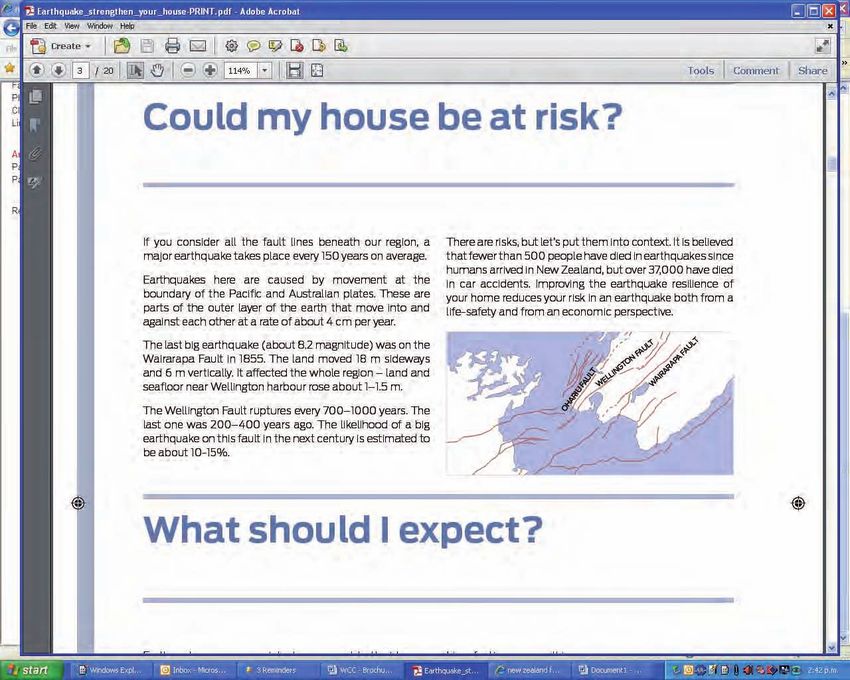
If you consider all the fault lines beneath our region, a major
(environment Waikato). See also Fig 1 (page 5)
earthquake takes place every 150 years on average.
EARTHQUAKE PRONE BUILDINGS – WCC GUIDE 5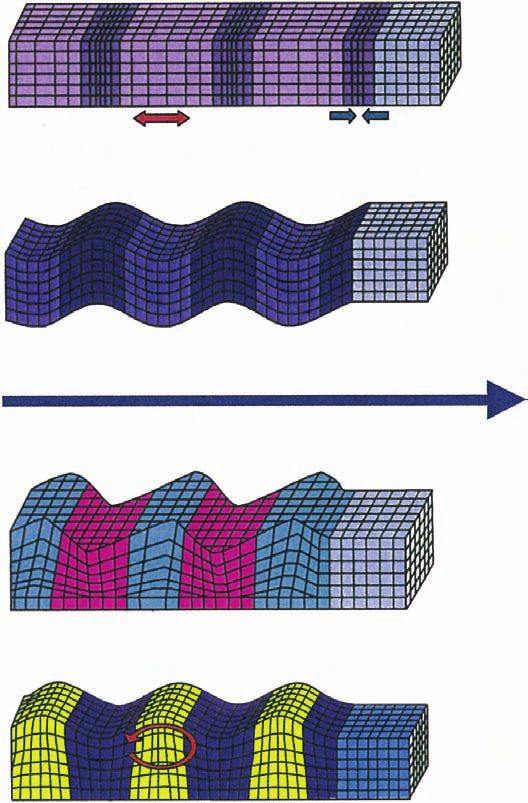
1.0

Earthquakes here are caused by movement at the boundary of the
Pacific and Australian plates.
These are parts of the outer layer of the earth that move into and
against each other at a rate of about 40mm per year.
The last big earthquake (about 8.2 in magnitude) was on the
Wairarapa Fault in 1855. Land moved 18m sideways and 6m
vertically. It affected the whole region – land and seafloor near
Wellington harbour rose about 1–1.5m.
The Wellington Fault ruptures every 700–1000 years. The last big
one was 300–500 years ago. The likelihood of a big earthquake on
this fault

   in the next century is estimated to be about 10–15 percent.

                                                                         THE LAST bIG EARTHqUAkE
                                                                         (AbOUT 8.2 In MAGnITUDE)
                                                                         WAS On THE WAIRARApA FAULT
                                                                         In 1855. LAnD MOvED 18M
                                                                         SIDEWAyS AnD 6M vERTICALLy.
                                                                         IT AFFECTED THE WHOLE
                                                                         REGIOn – LAnD AnD SEAFLOOR
 FIgure 1.2: New Zealand showing plates and major fault systems          nEAR WELLInGTOn HARbOUR
 (environment Waikato).
                                                                         ROSE AbOUT 1–1.5M.

    6       EARTHQUAKE PRONE BUILDINGS – WCC GUIDE
1.0

                                                 Structure   p-Waves                              Push and pull

                                                                            Extension                 Compression

                                                             S-Waves                              Up and down

                                                                           Side to side

FIgure 1.3: Arrival of Seismic Waves at a Site                                            Direction of Energy Transmission

                                                             Love Waves                   Sideways in horizontal plane

                                                             Rayleigh Waves               Elliptic in vertical plane

                                                              FIgure 1.4: Motions caused by Body and Surface Waves
                                                              (Adapted from FeMA 99, Non-Technical explanation of the NeHrP
                                                              recommended Provisions)

                                                                               EARTHQUAKE PRONE BUILDINGS – WCC GUIDE        7
2.0

WELLInGTOn

There are a number of active faults identified as potentially affecting          Wellington has four subsoil classes - namely rock, shallow soil,
the Wellington region – the closest being the Wellington Fault and               deep or soft soil and very soft soil. As part of the ‘It’s our Fault’
the Wairarapa Fault. See Map 1.                                                  programme to understand the geological conditions present in
                                                                                 Wellington a database was compiled containing all the collated
However other faults around the Wellington region are also active and
                                                                                 subsurface information. This was used to construct a 3D geological
capable of generating major earthquakes - for example the Ohariu
                                                                                 model and subsoil map of central Wellington (see right). The subsoil
Fault. The frequency of large earthquakes affecting the Wellington
                                                                                 map shows the nature of the sediments at or near the ground
Region is therefore much higher, with an average of about 150 years
                                                                                 surface in the central city. This map was created as these deposits
for a very strong or extreme ground - shaking quake.
                                                                                 have very different geotechnical properties and as such are like to
It is well documented that the earthquake risk in Wellington and the             behave differently under earthquake loading. The map can assist
surrounding region is the greatest in New Zealand.                               in site investigations by illustrating the most likely sediments found
                                                                                 at or just below the surface of a site.
                                                                                 The map should be used as a guide rather than a substitute
                                                                                 for site-specific investigations. Previous research concluded that
                                                                                 Wellington City is likely to experience varying levels of ground
                                                                                 shaking during a large damaging earthquake. Areas
                                                                                 most susceptible to ground shaking amplification and related
                                                                                 phenomena are the reclaimed areas on the waterfront and the
                                                                                 low-lying areas of Te-Aro.

 FIgure 2.1: Wellington region faults
                                                                                 THE CITy IS ExpOSED TO
The city is exposed to earthquake-induced hazards including
fault rupture, liquefaction and ground shaking amplification.
                                                                                 EARTHqUAkE-InDUCED
The geological makeup of the area is responsible for this exposure,              HAzARDS InCLUDInG FAULT
with a variety of ground materials present. A large proportion of
the central city is founded on sediments – expected to amplify
                                                                                 RUpTURE, LIqUEFACTIOn
strong ground motion.                                                            AnD GROUnD SHAkInG
The influence of local geological conditions (site effects) on the               AMpLIFICATIOn. THE
intensity of ground shaking and earthquake damage is well
documented. In New Zealand, site effects are dealt with in                       GEOLOGICAL MAkEUp OF
New Zealand Standard (NZS) 1170.5:2004 – which prescribes                        THE AREA IS RESpOnSIbLE
the structural requirements needed to ensure the buildings are
properly designed for ground conditions at the site.                             FOR THIS ExpOSURE, WITH
                                                                                 A vARIETy OF GROUnD
                                                                                 MATERIALS pRESEnT.

    8       EARTHQUAKE PRONE BUILDINGS – WCC GUIDE
2.0

                                                                             LIqUEFACTIOn
                                                                             The Canterbury earthquakes have illustrated the great damage that
                                                                             can result from liquefaction. The potential for liquefaction is not
                                                                             limited to Christchurch and its surrounds – several cities and towns
                                                                             in New Zealand are built on potentially liquefiable land.

                                                                             What is liquefaction?
                                                                             Liquefaction is the process that leads to a soil suddenly losing
                                                                             strength, most commonly as a result of ground shaking during
                                                                             a large earthquake. Not all soils however, will liquefy in an
                                                                             earthquake. The following are particular features of soils that
                                                                             potentially can liquefy:
                                                                                 Loose sands and silts. Such soils do not stick together the way
                                                                                 clay soils do.
                                                                                 Soil that sits below the water table, so all the space between
                                                                                 the grains of sand and silt is filled with water. Dry soils above
                                                                                 the water table will not liquefy.
                                                                             In a strong earthquake, the shaking may be so strong that the
                                                                             sand and silt grains try to compress the spaces filled with water,
                                                                             but the water pushes back and pressure builds up until the grains
                                                                             float in the water. Once that happens the soil has lost its strength
                                                                             and has liquefied.
                                                                             Liquefied soil, like water, cannot support the weight of whatever is
                                                                             lying above it – be it the surface layers of dry soil, concrete floors,
                                                                             or building foundations. Liquefied soil under that weight is forced
                                                                             into any cracks and crevasses it can find, including those in the dry
                                                                             soil above, or the cracks between concrete slabs. It flows out onto
                                                                             the surface as boils, sand volcanoes and rivers of silt. In some cases
                                                                             the liquefied soil flowing up a crack can erode and widen the crack
                                                                             to a size big enough to ’swallow’ a motor vehicles.

FIgure 1.3: Wellington city NZS1170.5:2004 site subsoil class maps.


                                                                                                 EARTHQUAKE PRONE BUILDINGS – WCC GUIDE         9
2.0

LIqUEFACTIOn AnD ITS EFFECTS
before the Earthquake
Area of flat, low lying land with groundwater only a few metres
below the surface, can support buildings and roads, buried pipes,
cables and tanks under normal conditions.

                                                                                           Clayay soil

                                                                                                                        River
                                                               Dry fine sand and silt

                                                               Fine sand and silt below the watertable

During and after the Earthquake
During the earthquake fine sand, silt and water moves up under            Lateral Spreading – River banks move toward each other. Cracks
pressure through cracks and other weak areas to erupt onto the            open along the banks. Cracking can extend back into properties,
ground surface. Near rivers the pressure is relieved to the side as       damaging houses.
the ground moves sideways into the river channels.
Sand boils (Sand volcanoes) – Sand, silt and water erupts upward
under pressure through cracks and flows out onto the surface.
Heavy objects like cars can sink into these cracks. Sand, silt and
water cover the surface.
Power poles are pulled over by their wires as they can’t be
supported in the liquefied ground. Underground cables are
pulled apart.

                      Sand Boils (Sand Volcanoes)
                                                                                                              Lateral Spreading

                                                               Fine sand and silt liquefies, and water pressure increases

Tanks, pipes and manholes float up in the liquefier ground and
break through the surface. Pipes break, water and sewage leaks
into the ground.

    10      EARTHQUAKE PRONE BUILDINGS – WCC GUIDE
2.1
pOLICy AnD SCOpE
All local councils in New Zealand are required by the Building bUILDInGS ExCLUDED FROM
Act 2004 to develop and implement a policy to determine which
THE COUnCIL pOLICy
buildings might be prone to significant damage as the result of
an earthquake. The design requirements for buildings in Wellington have been
progressively toughened since earthquake design began with the
When Wellington City Council developed and implemented its policy, introduction of NZS 95 in 1935. This was followed by NZS 1900,
it had the benefit of more than 30 years’ experience in strengthening Chapter 8, then by NZS 4203 in 1976, by the Building Act 1991 and
quake-prone buildings. The Council is also applying the lessons learnt now the Building Act 2004.
from the Canterbury earthquakes. One of our key objectives is to
collaborate with the community and organisations with expertise to Typically, the Council doesn’t assess buildings designed to the 1976
ensure that we are doing the best we can to strike the aforementioned NZS4203 standards and subsequent codes unless they have a critical
balance between risk and safety in a quake-prone region. structural weakness. To be excluded from the process, building
owners may have to provide evidence of the year of construction.
For the purpose of consistency, there is a theoretical ‘design-level
earthquake’ that all modern buildings must be built to endure. The reason for this is that from 1976 onwards various other factors
When assessing the performance of older buildings, they are have been introduced to take into account of the performance of
deemed ‘earthquake-prone’ if during an earthquake of only modern structural forms that use varied materials with improved
one-third the intensity of that standard they can be expected detailing standards.
to suffer partial or complete collapse, causing injury or death to That said, changes to the Building Act 2004 being flagged by the
people or damage to another property. Government could well see post-1976 buildings required to be
As well as the overall performance of the building, attention must assessed against specific criteria established under a revised
to be paid to those parts, such as heavy ornaments, chimneys and Building Code.
parapets, which constitute a greater potential hazard in of themselves.
Special attention will also be given to the intact survival of essential
LEGISLATIOn AnD WELLInGTOn CITy
emergency escape routes, such as stairs and ramps, and the COUnCIL pOLICy
securing of secondary systems such as suspended ceilings and
ventilation ducting. It is also recommended that building owners
Building Act 2004
and occupiers ensure large or delicate pieces of office furniture are
properly secured.
In Wellington, the assessment process is well underway. The Seismic
Building Building
Performance Programme being led by Wellington City Council, and Regulations 1992 Code
by 2014 all pre-1976 buildings in the city will have been assessed.
The Council will, over time, through continued engineering
assessments and associated research, further develop its database Approved
of buildings of varying ages, materials, and structural types, to allow Documents
for the targeting of resources for ‘at-risk’ buildings.
The register of confirmed quake-prone buildings, as referred to in Earthquake Prone
the City Council’s policy, is a subset of that overall data. Dangerous and Insanitary
Building Policy
For those interested in the state of a particular building, finished
assessments and relevant associated data will be available via Local Governmnet Offical
LIM’s Land
property files and on the Council’s website. Information and Meeting
Information Memoanda
Act 1987 Section 44a
EARTHQUAKE PRONE BUILDINGS – WCC GUIDE 112.2
ASSESSMEnT
There are three main stages for the assessment of Wellington’s Importance levels
buildings.
Importance Level Examples
1. Document Review 4 Civil Defence, hospitals, police stations
In the first instance research is carried out through Council records,
city archives and private documentation (where available) to 3 Cinemas, shopping malls
determine the history of the building and what (if any) previous 2 Normal commercial and large residential
upgrades may have occurred. buildings
2. Initial evaluation procedure (IEp) Importance-level 4 buildings are those with special post-disaster
Developed by the New Zealand Society of Earthquake Engineering functions.
(NZSEE), the IEP provides an indication of a building’s seismic
Importance-level 3 buildings are those that contain people in
performance relative to the minimum strength to which a modern
crowds or contents of high value to the community.
building would have to be constructed.
Importance-level 2 buildings are those that make up the bulk of
The result of this assessment is a percentage score of the
the city’s built environment and are simply those that do not fall into
New Building Standard (%NBS) from which it is possible to
the other categories.
determine whether a building is potentially quake-prone (less
than 34 percent). The Council has contracted structural engineers Heritage Buildings are those listed in the District Plan, in the
to carry out the assessments. Historic Places Trust register or other significant buildings or
structures forming part of a conservation area or special character
Where a building owner has already completed such an assessment
area. Heritage buildings are assessed using the same criteria as
or wishes to have one carried out sooner, the Council is willing to
non-heritage buildings.
accept an independent IEP or detailed assessment report – provided
the information is substantial and can be reconciled with any 3. Detailed engineering evaluation (DEE)
existing structural reports. Where a building has been identified as potentially quake-prone by
The independent report may be peer-reviewed by the Council’s the IEP process, the Council contacts the owner and requests that
contracted engineers. they get an engineer to carry out a detailed assessment.
Any detailed assessment should provide an accurate measure of
% NBS, which will supplement any IEP scores held on file.
The detailed assessment will make use of relevant materials
standards and New Zealand and/or overseas publications. Average
known or measured strengths of materials may be used when
assessing ultimate capacities of structural elements.
FIgure 2.2: IeP format (refer to appendix 1)
12 EARTHQUAKE PRONE BUILDINGS – WCC GUIDE2.3
nOTIFICATIOn AnD
REpORTInG
COUnCIL ASSESSMEnTS FORMAL nOTICES
As each IEP is completed, the result will be notified to the building In accordance with s124 and s125 of the Building Act 2004, the
owner. Buildings with a resulting NBS of less than 34 percent will Council will attach a written ‘Section 124’ notice (yellow notice) to
be declared potentially quake-prone and owners will be given six the building requiring the owner, within a time stated in the notice,
months to provide additional information to allow for the review of to adequately reduce or remove a danger so that the building is no
the final IEP grading. longer earthquake-prone.
IEP details showing the percentage of NBS will be available to the Copies of the notice will be provided to the building owner, occupier,
public via LIM reports. The reports will also be accessible in property and every person who has an interest in the land, or is claiming
files. Buildings not considered quake-prone will also have the an interest in the land – including the Historic Places Trust, if the
percentage of NBS and other details placed on the property file to building is a scheduled or registered heritage building.
provide a record that an assessment has been carried out.
When the yellow notice expires (10, 15 or 20 years depending on
When the Council is satisfied that a building, or part thereof, is the category of building). At the expiry of the stated time period in
quake-prone it will issue an Earthquake-prone Building notice. the orange notice, the Council contacts the owner and inspects the
building to ascertain whether the notice has been complied with.
Note:
If no strengthening work has been done,
The reference to new building standard (NBS) is likely to be replaced
a red notice is issued to the owner and attached to the building
with reference to ultimate limit state (ULS) in the near future as a
which means the building cannot be occupied until strengthening
better reflection of the nature of the assessment.
work has been carried out and failure to comply within the stated
time period could result in the building being demolished.
IT IS THE RESpOnSIbILITy OF Building owners are encouraged to approach the Council and
bUILDInG OWnERS TO EnSURE discuss what options are available to them. The purpose of these
discussions will be to develop an agreed approach for the building.
THEIR COnTACT AnD MAILInG Building owners are also encouraged to obtain an IEP report to
DETAILS ARE kEpT Up TO work out whether their building is quake-prone and to forward a
DATE WITH WELLInGTOn CITy copy of the report to the Council for inclusion on the register if
one has not already been carried out and recorded through
COUnCIL. SEISMIC pERFORMAnCE Council assessments.
ASSESSMEnTS ARE COnDUCTED The Council will keep, and update as necessary, a register of
all buildings for which an initial evaluation (IEP) has been done.
On EnTIRE bUILDInGS RATHER The register records details of the outcome of the assessments
THAn InDIvIDUAL UnITS, AnD and details of any notices which may have been issued. In addition,
the register will include the details of any assessments that have
WE SEnD OUR REpORTS TO THE shown a building to not be quake-prone.
pRIMARy LISTED COnTACT. Please note that reports provided by, or on behalf of, an owner
may be deemed confidential and only available with the
authorisation of the building owner or responsible agency. It may
be prudent for prospective owners to obtain a copy of the reports
from the building owner.
EARTHQUAKE PRONE BUILDINGS – WCC GUIDE 132.3 2.4
RESOLUTIOn
The confirmed list of quake-prone buildings is published on our SEISMIC pERFORMAnCE IMpROvEMEnT
website Wellington.govt.nz and updated monthly. NB If the Council
Once a building has been identified as quake-prone, the building
has received no correspondence from the owner to the contrary
– or it’s parts identified as significant hazards – will be required
the building will be deemed quake-prone on the basis of the
to be strengthened to no less than 34 percent of the New Building
IEP findings.
Standard. The Council will consider any reasonable approach
Note: proposed for improving the seismic performance of a building.
Receipt of reports: it is the responsibility of building owners to The proposed work will be assessed on a case-by-case basis,
ensure their contact and mailing details are kept up to date with taking into account the requirements of the Building Act 2004.
Wellington City Council. Seismic performance assessments are Guidance on building assessment and strengthening is available
conducted on entire buildings rather than individual units, and we from a number of sources, including the NZSEE.
send our reports to the primary listed contact. As there are cases
In recognition of the NZSEE recommendations and potential
where that primary contact is different to the leaseholder of the
recommendations or legislative changes arising from the Canterbury
building, it is important that there is good communication between
Earthquake Royal Commission, the Council recommends that all
all parties.
building owners issued with an EPB notice seek to upgrade to at
LIMS – Land Information Memoranda are issued by the Council least 67%NBS. Where such a recommendation is made by the
under Section 44A of the Local Government Information and Royal Commission or change made to the Building Act, the Council
Meetings Act 1987. This legislation requires the Council to provide reserves the right to immediately and to full effect modify the policy
documents including consents, certificates, notices orders or to adopt a higher standard.
requisitions that may affect a section of land or any building on
Any upgrade requirements will immediately be superseded by the
the land Information relating to any possible current quake-prone
new requirement – and having upgrade work carried out to bring the
status is included.
building to the 34%NBS will not prevent the Council issuing a new
In LIMs, the Council will include a copy of the initial evaluation notice to a higher level.
process (IEP) assessment (if one exists) and a copy of the latest
The timeframe for strengthening or demolition starts when the
letter notifying the owner/s of what the current quake-prone status
notice is first issued.
of any building. If the building owner/s has had a re-assessment
done and the quake status has changed, the latest letter will High priority – 10 years
mention this. In some cases, where a new IEP has been done, Moderate priority – 15 years
this may be included in a LIM. If any building is yet to be assessed
or if a Sec 124 (yellow) notice has been issued against a building, Low priority – 20 years
this would also be mentioned in a LIM. A copy of the notice issued
would be attached. THE TIMEFRAME FOR
STREnGTHEnInG OR
DEMOLITIOn STARTS WHEn
THE nOTICE IS FIRST ISSUED.
14 EARTHQUAKE PRONE BUILDINGS – WCC GUIDE2.5 2.6
HERITAGE SUppORT
Heritage buildings are those that, individually or as part of a The Council’s role is to ensure the requirements of the 2004
collective community, hold historical value for our society. Building Act and the Council’s Earthquake-Prone Buildings Policy
Buildings with heritage value are classified in various ways; they are are fairly applied.
scheduled under the District Plan, are covered by a conservation
In addition to the Council’s regulatory role our officers seek to work
area or special character zone under the District Plan, and or are
closely with building owners whose buildings have been found to
registered under the Historic Places Act 1993.
be quake-prone exploring what options may be available to help
The Council believes the survival of heritage buildings should be strengthen the building.
actively promoted. The Council does not want to see strengthening
The Council’s earthquake resilience team provide advice and
work adversely affect the intrinsic value of these buildings. If a
guidance for building owners to obtain the necessary planning
detailed structural assessment confirms a building is quake-prone,
and or building approvals for construction, strengthening and
the Council will work with the owners to develop a mutually-
refurbishment of the building.
acceptable solution. When a heritage building is confirmed as
quake-prone notices are issued regardless of its heritage status. When strengthening options are not viable, the Council will
endeavour to assist the owner with the regulatory process
necessary for demolition.
The earthquake resilience team is also available to help facilitate
meetings between adjoining building owners to explore the possible
benefits of strengthening both buildings at the same time.
The team can also help owners plan a strengthening programme
and determine what work should be prioritised to improve the
earthquake-resilience of the building.
The Council is also working with the Government and other
institutions to see where assistance can be given to owners faced
with strengthening at-risk buildings.
Overall, the Council’s goal is to be as helpful as possible while
running a building-strengthening programme that helps to improve
the earthquake-resilience of our city.
Council provides for owners of Heritage Buildings, the built Heritage
Incentive Fund that helps fund the earthquake strengthening work.
Details are available on our website.
EARTHQUAKE PRONE BUILDINGS – WCC GUIDE 152.6
AS pART OF THE COUnCIL’S
REGULATORy ROLE OUR OFFICERS
SEEk TO WORk CLOSELy WITH
bUILDInG OWnERS WHOSE
bUILDInGS HAvE bEEn FOUnD
TO bE qUAkE-pROnE, ExpLORInG
WHAT OpTIOnS MAy bE AvAILAbLE
TO HELp STREnGTHEn THE
bUILDInG.
Following the 1931 Napier earthquake, the clock tower and roman
style entrance were removed from the Wellington Town Hall to make
the building safer.
The Town Hall today, which we will begin strengthening later this year.
16 EARTHQUAKE PRONE BUILDINGS – WCC GUIDE3.0 3.1
STRUCTURAL ELEMEnTS
pERFORMAnCE OF COnCERn
There is no such thing as a quake-proof building. Most buildings are An owner’s decision on whether to strengthen a building, or to
designed to safeguard life in an earthquake. For example, a building demolish and rebuild a replacement structure that complies with
may end up uninhabitable and beyond reasonable repair – but the current earthquake-strengthening criteria, depends on the required
occupants will be able to get out safely. building performance as well as the associated costs. In this section,
a generic retrofit strategy is described that begins with the most
A typical building designed and built to the building code that is
basic (and important) items to address with the primary aim of
exposed to a one-in-500-year earthquake is expected to withstand
ensuring public safety.
the effects of that earthquake (ground shaking) without collapse.
The building may be damaged beyond repair but should not suffer a Additional retrofit measures may be taken beyond these to further
catastrophic collapse from shaking up to that level. improve building performance in order to minimise damage to
the building and contents – with the highest performance target
Buildings of critical importance following a quake –such as
conceivably being to have the building and its contents suffer no
hospitals, fire and police stations and communications centres –
damage and be immediately functional following an earthquake.
must be designed to a higher code standard and are designed for
the effects for a one-in-1000 or 2500 year quake. Older buildings usually have a number of inherent structural
For example, base isolators have been used in the construction of features that make them prone to quake forces. Many of these
Wellington Hospital – this reduces the effects of an earthquake on features can often be addressed without significant alteration to the
building – resulting in a relatively large increase in strength. The big
the structure and the likelihood of significant damage that would put
problem is that New Zealand’s early unreinforced masonry (usually
the hospital out of action after an earthquake.
brick) buildings or unreinforced concrete buildings were simply not
The Christchurch quakes produced levels of shaking twice the designed for earthquake loads and while these early buildings can
code design level and many buildings were badly damaged. Of the be made to perform adequately in a quake, they lack a basic degree
buildings that did collapse, many were older unreinforced masonry of connection between structural components to allow all parts of
buildings that were not designed to current code requirements and the building to act together.
would have been considered quake-prone.
Therefore, the basic philosophy followed here is to first secure
The Council’s earthquake resilience programme aims to determine non-structural parts of URM buildings that represent falling hazards
which buildings are quake-prone and work with the owners to have to the public (eg chimneys and parapets) followed by improving
their buildings strengthened where the Council’s assessment shows the connections between the structural elements (roof, floors and
they are below 34 percent of NBS. walls), strengthening of specific structural elements, and possibly
The Council encourages owners to strengthen to above the 34% adding new structural components to provide extra support for the
NBS threshold and in some situations the Building Act 2004 may masonry building.
require a higher level of strengthening. Chimneys and parapets
Buildings on strategic routes will be a priority for assessment and In a strong quake, chimneys and parapets can rock on their
strengthening. supports and topple over. The simplest solution is to remove
these elements. Another option is to tie them back into the roof
The Council will continue to encourage and work with owners to
structure. Implementation of this tying back is usually comparatively
secure the facades, parapets, verandas and similar features and
straightforward and inexpensive.
make sure that such features do not pose a risk to the building’s
occupants and passers by. The Council will also work with the owners Gable end walls
of adjoining buildings to see if there is a mutually-beneficial outcome Gable end walls sit at the ends of buildings with pitched roofs.
in jointly strengthening buildings in a block rather than individually. If this upper triangular portion of the wall is not adequately attached
Building owners may find that the options to strengthen are not to the roof, the gable end is vulnerable to collapse.
viable and in this situation the Council will work with the owners Out-of-plane wall failure
and assist them in the regulatory process for the demolition of the Unreinforced masonry walls, in particular are weak in ‘out-of-plane’
building and redevelopment of the site. bending and therefore are susceptible to failure. Cavity walls that
EARTHQUAKE PRONE BUILDINGS – WCC GUIDE 173.1 3.2
SEISMIC RETROFIT
SOLUTIOnS
are missing wall ties, or have wall ties that are badly deteriorated, Owners looking at strengthening their building should talk to a
are especially vulnerable. The addition of wall-to-ceiling or floor structural engineer and architect in the first instance.
diaphragm (additional inter-storey support) anchors serves to reduce
The following are some of the questions they should consider:
the vertical slenderness of a wall as well as make the building work
together as a whole, rather than as independent parts. How much longer is the building’s life?
Floor and roof diaphragm failure Is it likely to have a change of use?
In some cases, the floor and roof diaphragms, typically constructed What are the issues that make it earthquake-prone?
of timber, are excessively flexible. This flexibility results in the walls
connected to these diaphragms undergoing sufficiently large ‘out Does it have heritage value?
of-plane’ deflections resulting in major wall damage and collapse. How much will it cost to do/or not do the strengthening work?
Once these questions have been addressed and the owner
wishes to proceed with strengthening the following are some
options/solutions.
MATERIAL STAbILISATIOn/MAInTEnAnCE
Aim: to ensure the existing structural components of a building are
maintained properly.
In-plane wall failures (piers and spandrels) Ongoing building maintenance should be undertaken to ensure that
When ‘out-of-plane’ failures are prevented, the building is able the masonry elements (walls, parapets, chimneys and facades),
to act as a complete entity and in-plane wall failures can occur. and the timber roof and floor elements, are in sound condition.
It should be noted that, in this condition, building strength is often Deterioration of the fundamental building elements compromises
not far off the full design strength requirements. Strengthening of the ability of the ‘as-is’.
piers and spandrels can result in further increases in overall building
strength. The seismic retrofit strategy for a building in this condition The bricks (and particularly the mortar) used in URM buildings
might be to improve the building’s displacement capacity, rather deteriorate in the environment over time. Occasionally this
than institute any further increase in strength. This intervention deterioration will result in local failures and cracking which affects
could be achieved by locally reinforcing the masonry spandrels the overall strength of the building.
and/or piers. Alternatively, ductile steel or concrete frames can be Various external issues/events such as dampness, subsidence,
inserted internally to provide the in-plane shear strength needed, earthquakes and external impacts can also cause cracking and
while also helping with some or all the gravity load-carrying damage in the masonry elements. Deterioration can often be
function of the masonry walls. remedied by reinstatement and re-pointing of mortar, but
Return wall separation sometimes more substantial measures are required. There are
This type of failure is particularly dangerous because it allows a wall various techniques for the repair of cracks, securing of lintels,
over the entire building height to fall outwards. This failure mode and reinstatement of damage.
can be prevented by the use of anchors installed along the vertical Bonding agents such as grout or epoxy can be injected into the
intersections between walls. mortar and there are also several metal-based types of inserts,
pounding failure such as shaped dowels or reinforcing bars, which can be used to
This failure can only occur when there is insufficient space between reinstate and strengthen the brickwork.
adjacent buildings so that they bang into each other (when vibrating
laterally) during an earthquake. Widespread examples of pounding
damage to buildings were observed in the Canterbury earthquakes.
18 EARTHQUAKE PRONE BUILDINGS – WCC GUIDE3.2
The basic strategy to eliminate these falling hazards is to fasten
them to the rest of the structure, normally through the use of ties or
anchors back to the roof structure.
Note:
Many of these failures were seen during Canterbury earthquakes,
where parapets not only fell towards the footpath/street, but also
fell onto the building’s awning or canopy that projects above the
pedestrian access, and resulted in collapse of that element as well. In
cases of multi-storey buildings with parapet failures, the parapets fell
across the footpath and well into the street, crushing cars and buses.
URM buildings will often feature numerous decorative elements
built with brick and plaster which are important parts of the
building’s architectural character – such as parapets, chimneys,
gable walls, and other, smaller, decorative features. In the past,
Deteriorating mortar between bricks
some buildings have had these elements removed wholesale,
rather than the elements being strengthened or secured. Parapets
The visual impact of reinstatement and strengthening can be
and chimneys are usually the first parts of a building to fail in
minimal if done carefully, and the result is potentially far superior
an earthquake. Parapets in particular are comparatively simple
to a cracked and broken façade. However, such measures are often
to strengthen. Generally, a continuous steel section running
irreversible and care needs to be taken with colour matching and
horizontally along the length of the parapet, which is fixed back to
the concealment of holes drilled for inserting rods.
the roof structure behind, is a suitable technique (if a little crude).
Lintels and arches will sometimes require strengthening, particularly The back of a parapet is rarely seen, which makes the visual impact
when these elements are constructed from URM. One of the best of this method low. Some would argue that chimneys contribute to
ways to achieve this intervention is by using drilled and inserted the architectural form of a building and often help define the front
rods which are grouted (or epoxy anchored) into place. These rods elevation or a roof profile and, as such, should be preserved
provide the requisite tensile strength to the structural element while if possible. The securing of chimneys is more complex than
posing little visual impact. securing parapets and gables, but can usually be achieved by
fixing them to the building diaphragms at each level and, either
pARApETS AnD OTHER FALLInG HAzARDS strengthening the projecting portion, or bracing it back to the roof
structure with steel members similar to the methods used for
Aim: to secure or remove falling hazards.
parapet restraint, or fixing steel sections to the sides to provide
The greatest threat to public safety posed by URM buildings is that flexural strength. A number of strengthening solutions are available
of falling masonry. This hazard can be due to chimneys that fail by for bonding to the surface of masonry elements and may be
rocking (usually at the roofline) and fall through the building’s roof or appropriate where the exterior has been plastered.
over the side of the building. Parapets that are not properly secured
to the building can fail similarly. Because of their location along
the front and sides of commercial buildings – and because they
typically fall outwards towards the footpath/street, parapets pose a
very high danger to the public. Gable-end walls are another form of
this out-of-plane failure and, similar to parapets, gable walls almost
exclusively fall outwards. Where the gable walls are adjacent to
public spaces, they also pose extreme danger to the public.
EARTHQUAKE PRONE BUILDINGS – WCC GUIDE 193.2
It is also possible to replicate a chimney in lighter more
earthquake-resilient materials that considerably lower the risk One approach to this problem has been to fill the cavity
of failure in an earthquake. However, ideally, they should be with reinforcing steel and a cementitious grout. This bonds
strengthened or removed completely. the outer leaf to the inner leaf and also forms a reasonably
strong shear wall which is hidden from view. However
Other elements that constitute falling hazards, such as decorative
this approach fails to consider the purpose of a ventilated,
plaster features on the face of a wall, can be effectively fixed with
drainable cavity. When a cavity is filled, not only is the
a single bolted connection. Less secure elements, such as plaster
ventilation route blocked, but water penetrating the outer
finials or balusters, can be fixed with a single adhesive anchor
leaf is transferred directly to the inner leaf via the grout fill,
connected to a strand of stainless steel wire to mitigate the falling
which results in moisture penetration into the building.
hazard. However, more complex strengthening work may be
As a consequence, dry rot can develop in wooden areas
necessary in some cases.
such as doors, window frames and skirtings – causing
extensive damage. While a filled cavity may seem to be an
WALL STREnGTHEnInG TO RESTRAIn excellent strengthening solution, it is the ventilation and
‘OUT-OF-pLAnE’ bEnDInG drainage ability of a cavity that is the main priority.
Aim: to prevent ‘out-of-plane’ failure of walls by increasing their The filling of a cavity with cementitious grout does not take
flexural strength or reducing the vertical and horizontal distance into account the incompatibility between rigid cementitious
between their supports. mortars and grouts, and the weaker lime mortars used in
URM walls are weak when subjected to forces other than early buildings. These materials are incompatible in terms
compression. Even when fully secured to floors at each level, of both strength and permeability, with the difference in
‘out-of-plane’ forces can cause significant wall bending depending permeability potentially leading to a number of detrimental
on the ratio of the height between levels of support to the effects on the original performance of the building.
thickness of the wall. Some walls have sufficient thickness, or Softer, permeable materials, such as bricks and the lime
have cross-walls or buttresses, that help them withstand these bedding mortar will deteriorate over time as a result of the
out-of-plane forces without modification – however many walls weathering process. Cementitious materials trap water
need strengthening. There are a number of approaches to combat against the more porous, softer elements causing extensive
this problem as further described below. erosion of soft brickwork leading to the loss of original
fabric due to the need for brick replacement.
brick cavity walls – (outer leaf fixing)
The outer leaf of a cavity wall is problematic as it is particularly Efflorescence can also develop in structures as a
prone to failure by peeling off outwards. Steel ties, commonly consequence of changing the way that moisture is
installed to connect this layer to the more robust wall behind, are transferred through a building, and by introducing
subject to deterioration and are sometimes missing – requiring cementitious grouts and mortars containing soluble salts.
attention during retrofits. This efflorescence can cause extensive damage to both
external brickwork and internal plaster finishes.
The preferred approach to re-attaching the outer leaf is to use a series
of proprietary corrosion-resistant ties which are drilled through the
face layer and are epoxy-anchored into the structure behind.
The visual impact of these ties is minimal, although care needs to
be taken when concealing drilled holes. These ties are irreversible,
but their presence is visually negligible.
20 EARTHQUAKE PRONE BUILDINGS – WCC GUIDE3.2
Inter-floor wall supports to disguise the steelwork. However, care must be taken to ensure
A series of vertical steel sections can be bolted to the inside face the struts are visually unobtrusive. Both of these techniques can also
of the wall with sufficient spacing to ensure that the width of be done by substituting the steel with concrete, where this is more
wall between supports is capable of resisting the out-of-plane visually-suitable or less commonly, with timber. Steel struts can also
forces. In a quake these sections bend to transfer wall loads to the be recessed within the width of the wall. Recessing the members
adjacent floor diaphragms, essentially breaking up a large planar results in an irrecoverable loss of material and may result in other
wall into a number of buttressed segments. This simple method complications such as cracking – although recesses may
may be suitable in, for example, an industrial building where visible be preferable if used beneath a plastered surface, as it will not
steel bolted to the walls is in keeping with the character of the affect the interior space. Concrete sections will have larger
building – or in other buildings where the steel can be made to cross- sections than steel sections – and will therefore be more
be architecturally appealing. If there is existing internal framing intrusive. In addition, once cast, concrete is difficult to remove
with space behind for these columns, and no historic material is without significant damage, particularly from a porous and naturally
lost during installation, then it is a perfectly acceptable method. coloured material like clay brick. The installation of in-situ concrete
Sections generally fix to the historic material with bolts only, is a comparatively permanent measure, so any activity which
which allows a high degree of reversibility. requires concrete to be cast against brick should be given careful
thought before being undertaken.
post-tensioning
Post-tensioning is an effective method for increasing the
out-of-plane strength of URM walls. The post-tensioning may be
applied externally or installed internally by drilling vertical cores
through the middle of a URM wall and then inserting steel rods
into these cores. The rods may or may not be set in grout, and are
then tensioned, which provides an additional compressive force in
the wall.
This loading modifies the stress behaviour of the URM in bending –
so instead of bending instantly, the wall remains in compression.
This also results in an increase in the shear strength of the wall,
making post-tensioning an attractive strengthening solution.
Internal post-tensioning has little visual impact, although its
installation may be unsuitable in some buildings as access is
In the past, rather than only supporting the URM walls for out-of-plane required to the top of the wall, and walls need to be of a certain
actions, these inter-floor wall support systems have been conceived minimum thickness. Drilling cores involves some loss of historic
as a method to support the floors in the event that the walls fail material from the holes, though compared to some methods this is a
and collapse. A technique similar to the installation of vertical steel minor impact. If the bars are fully grouted in place, post-tensioning
members is to provide a horizontal steel member at the mid-height is essentially irreversible, although this does not necessarily have
of the wall and brace this with diagonal struts up to the floor or to be done. The presence of post-tensioning bars is not likely to
ceiling diaphragm above. This technique might be more suitable result in any negative effects to the historic material should their
than the installation of vertical members if there is a cornice part function no longer be required, provided care is taken with all
way up the wall which needs to be conserved, or which can be used core reinforcement to ensure that it is adequately protected from
corrosion. This problem can be completely avoided by using plastic
coated steel or FRP bars.
EARTHQUAKE PRONE BUILDINGS – WCC GUIDE 213.2
FLOOR AnD ROOF DIApHRAGM STIFFEnInG
Aim: to increase in-plane stiffness of horizontal diaphragms
(floors and roof) so seismic forces can be efficiently transferred to
masonry shear walls.
Diaphragms are useful because they provide a layer through
which lateral forces can be distributed to remote resisting elements.
They also act to bind the whole building together at each level.
A building that acts as one rigid body rather than a number of
flexible panels is far more likely to survive an earthquake.
Timber floor diaphragms consist of three main elements; chords,
sheathing material, and supplementary structure. To form a
diaphragm in a typical URM building, chords have to be established
and mechanical fastenings added to take shear and tensile loads.
Several secondary fastenings between the chord and the floor
FrP, used to reinforce columns or roof may also be required depending on the technique used.
Some tensile ties will penetrate to the outside of the building
There are other methods of core reinforcement, with the most and others will be drilled and epoxyed in place. Existing historic
common being non-stressed steel bars set in grout, where the sheathing may prove inadequate and require strengthening or
steel reinforcement only becomes stressed when the wall is loaded an additional layer of more rigid material.
laterally. The visual impact and reversibility of these methods are
the same as for fully grouted post-tensioning, although they are less Ties to the outside of walls may require metal load spreaders which
effective structurally. visually impact on the exterior. Many New Zealand buildings display
these, and they seem to have become somewhat accepted as part
Wall reinforcement (FRp and other materials) of the strengthening process. Nevertheless, care needs to be taken
A number of other methods may be used to provide out-of-plane when considering their visual impact and invisible solutions may
stability of unreinforced masonry walls, such as the use of strips be preferable. Much of the additional required work can be hidden
of fibre – reinforced polymer (FRP) fitted into vertical saw cuts in within the floor space, but if this is exposed or the connections are
URM. This technique is known as near-surface mounting (NSM). extensive, special attention will be required to preserve the visual
It is a relatively recent technique that involves the epoxying of FRP character of the inter-floor space.
into saw cuts in the surface of the URM and covering the cut with
Diaphragm-strengthening may have some visual impact if new
a grout mixed with brick dust. This technique would have some
sheathing material is required. Historic flooring material is often
visual impact in naked brick, but little if done within an existing
a significant contributor to the character of a place and ought to
grout line, and none if installed in plastered walls being re-pointed.
be retained in view whenever possible. If the existing sheathing is
This technique can be a particularly effective and non-intrusive
inadequate, a ceiling diaphragm below, or stiffening the existing
method of strengthening, although the finishing of this system is
material might be preferable to covering it. Another approach is to
noticeable and work needs to be done to conceal the inserts.
remove the existing sheathing and install a structural layer beneath
it. This exercise requires extreme care; firstly because existing
sheathing, particularly tongue and groove, is very easily damaged
during removal and secondly care needs to be taken to restore the
boards in the correct order.
22 EARTHQUAKE PRONE BUILDINGS – WCC GUIDE3.2
Diaphragms formed using mechanical connections have a high COnnECTIOn OF STRUCTURAL ELEMEnTS
degree of reversibility. When ties are epoxyed into walls there is
Aim: to ensure adequate strength of roof-to-wall, floor-to-wall
less reversibility, but minimal visual intrusion. Additional sheathing
and wall-to-wall connections. Good connectivity between the
may damage or alter the nature of the historic timber below, making
walls and the floor and roof diaphragms will ensure that the walls
it less desirable as a solution – although this can be mitigated.
only deflect outwardly over the height of one storey of a building.
Occasionally, pouring concrete over an existing timber floor may
This reduces the out-of-plane displacements that lead to wall
be considered. This solution can greatly increase the stiffness of the
collapse. Similarly, good connectivity along the vertical intersection
building, but in turn increases its weight and therefore the forces
of walls meeting at corners of a building (or internal walls meeting
acting on it. It also completely changes the material of the floor and
with an external wall) will ensure that the building responds as
is not a reversible action, because even if it can be removed, the
a single structure and not as separate, isolated components.
concrete would essentially destroy the character of the underlying
Much better performance can be expected in an earthquake when
timber. This procedure is therefore not recommended except in
the building responds as a single structure.
exceptional circumstances.
The most problematic deficiency in URM construction is inadequate
Roof diaphragms where the structure is exposed are slightly
connection of diaphragms to walls, as a failure of these connections
different, as the inclusion of a plywood diaphragm above timber
can potentially lead to the total collapse of a building. The addition
sarking is generally acceptable if this area can be accessed – for
of a network of small ties can substantially increase the strength
example if the roofing is being replaced. This installation can also
of a building by fixing the walls to the floor and roof diaphragms.
help to protect the sarking beneath. Roofs with suspended ceilings
These ties have to resist two actions: shear from the diaphragms
can be made to accommodate cross bracing, struts, and more
trying to slide across the walls; and tension from the diaphragm
innovative solutions as they can be hidden within the ceiling space.
and wall trying to separate. If these ties are missing, the walls
In instances where the roof provides little diaphragm action, or the
will act as a cantilever from the ground level under lateral loads,
forming of a diaphragm is uneconomical or impossible, a horizontal
and floors and roofs are far more likely to be dislodged from their
load-resisting member at the level of the top of the walls can be
supports, which is the most common mode of failure for URM
used to provide stability to the walls under out-of-plane loads.
buildings in an earthquake.
However, this member has to be fixed to stiff elements at regular
intervals to transfer horizontal loads, and these stiff elements may The use of simple metal anchors to connect the walls to the floor
have to be installed if other structure cannot perform this task. and roof diaphragms is relatively straightforward and was observed
in many buildings that survived both earthquakes in Christchurch.
Recently, some proprietary systems have become available.
They use steel reinforcement to connect walls to the floor and roof
diaphragms, and to provide wall-to-wall connection at corners and
other wall intersections. Typically, the reinforcement is placed in
horizontally-cored holes that pass through the entire building at
each floor level and at the roof level. The reinforcement is then
post-tensioned and grouted in order to clamp the walls to the
floors and roof and to each other. In some applications, vertical
reinforcement, sometimes with post-tensioning, is also used to
increase the compressive stress in the wall which improves the
wall’s quake strength when subjected to horizontal loads.
Floor diaphragm
EARTHQUAKE PRONE BUILDINGS – WCC GUIDE 23You can also read