Electromagnetically-excited noise mitigation techniques of electric motors used in EV/HEV applications - Jean Le Besnerais 21th ...
←
→
Page content transcription
If your browser does not render page correctly, please read the page content below
Electromagnetically-excited noise mitigation techniques
of electric motors used in EV/HEV applications

                                                Jean Le Besnerais
                                                contact@eomys.com
                                                21th June 2018

© EOMYS ENGINEERING 2013-2018   www.eomys.com                       1
What do we call electromagnetic acoustic noise and vibration?

  noise and vibrations coming from variable electromagnetic forces

   forces arising from the presence of a variable magnetic field : Maxwell & magnetostriction

      1. variable current source                    2. rotating permanent magnet       3. rotating DC current source

                                                                                                     I=constant
 Always present:
 Induction Machines (IM)
 Switched Reluctance Machines (SRM)                  Only present in PM-based motors           Only present in WRSM
 Permanent Magnet Synchronous Machines (PMSM)
 Wound Rotor Synchronous Machines (WRSM)
 Synchro Reluctance Machines (SyRM)

                                                                                            Renault Zoe - WRSM
        © EOMYS ENGINEERING 2013-2018     www.eomys.com                                                                2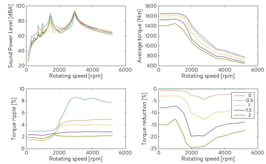
Case of Renault Zoe full electric vehicle (WRSM) – magnetic noise Vs non-magnetic noise

                             =                             +                            +

     Overall noise                      Aerodynamic &           Slot/pole interaction       Pulse Width Modulation
                                        mechanical noise       electromagnetic noise        electromagnetic noise
      Source separation done with LEA software [D91]

      © EOMYS ENGINEERING 2013-2018   www.eomys.com                                                            3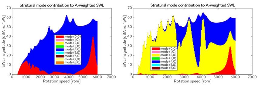
Resonance due to electromagnetic excitations
                                             EXCITATION FORCE
                                  Rotating excitation with r=2 minima and maxima along airgap
                                                     cos 2

  EXCITED STRUCTURE                                      felecf2

         © EOMYS ENGINEERING 2013-2018   www.eomys.com                                                               4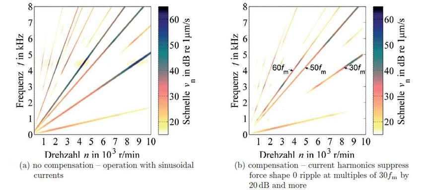
Spectrum of electromagnetic excitations
  •   Maxwell force spectrum in both discrete in time and space (along the airgap)
  •   Maxwell force concentrate at the interface between iron and air with a different spatial distribution
      pattern at each frequency « wavenumber »
  •   Ex: Prius 2014 IPMSM simulation with MANATEE® software

             r=-8,f=2fs                      r=0,f=6fs
                                                         •   The expression of excitation wavenumbers and frequencies highly
                                                             depends on machine topology and load state
                                                         •   Pulsating excitations (r=0) dominate the vibroacoustic
                                                             behaviour of traction motors in EV/HEV

        © EOMYS ENGINEERING 2013-2018   www.eomys.com                                                                    5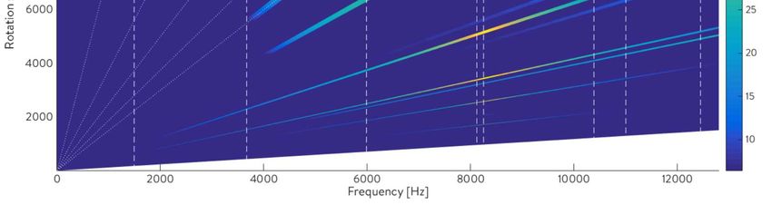
Main transfer paths of electromagnetic noise & vibrations (e-NVH)                                                         Example of r=1 excitation

 Circumf    Force            Transfer path      Description
 erential   direction
 wavenu
 mber
 r>0        Radial,          Air borne          Radial circumferential deflection of the outer stator yoke
            tangential                          and frame or outer rotor (rotating in forced regime,
                                                pulsating at resonance).                                       most common transfer
 r=0        Radial           Air borne          Radial pulsating circumferential deflection of the stator      path for e-NVH
                                                yoke and frame or outer rotor

 r=0        Tangential       Structural borne   Propagation of rotor torsional vibration to rotor shaft line
            (cogging torque                     and gearbox mount, or bearing sleeves and outer stator
            / torque ripple)                    frame

 r=0        Tangential       Air borne          Deflection of the outer stator yoke and frame or outer rotor
            (cogging torque                     following a unbalanced torsional mode due to particular
            / torque ripple)                    boundary conditions

 r=1        Radial           Air borne          Bending / tilting deflection of the outer stator frame or
            (unbalance                          outer rotor, in particular in clamped-free conditions
            magnetic pull)
 r=1        Radial           Structural borne   Propagation of rotor bending vibration to rotor shaft line
            (unbalance                          and gearbox mount, or bearing sleeves and outer stator
            magnetic pull)                      frame                                                             Adapted from J. LE BESNERAIS et al, « Bruit acoustique d'origine magnétique
 NA         Axial            Air borne          Axial deflection of the end-shields                                     dans les machines synchrones », Techniques de l’Ingénieur, 2013

        © EOMYS ENGINEERING 2013-2018      www.eomys.com                                                                                                                                   6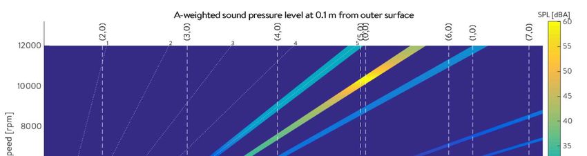
Noise mitigation strategies

   1. Lower excitation magnitude                   2. Lower structural response           3. Avoid resonances between
     Electromagnetic design engineers                    NVH design engineers
                                                                                             excitation and structure
     Software / control engineers                        Mechanical design engineers         NVH design engineers
                                                                                             Mechanical design engineers
                                                                                             Electromagnetic design engineers
                                                                                             Software / control engineers

         magnet width / shape                                  stiffening                        slot/pole combination
         slot opening optimization                             damping                           shift of natural frequency
         skewing                                               frame/lamination contact          shift of switching frequency
         current angle                                         boundary conditions               etc…
         short pitch / winding                                 etc…
         current angle / current injection
         notches / slits / flux barriers                                                                                        7
         spred spectrum switching
         etc…
       © EOMYS ENGINEERING 2013-2018     www.eomys.com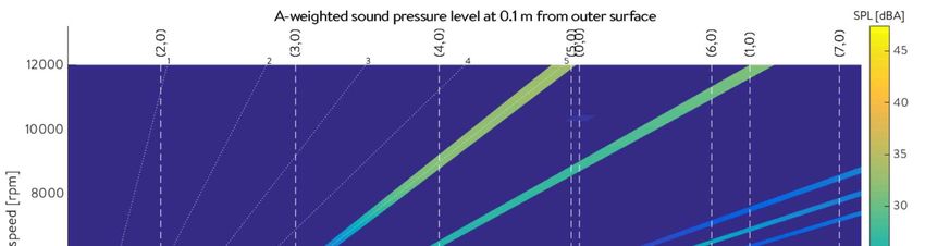
Choice of slot / pole combination

    •   Ex of low vibration and noise design rules given in books on induction machines:

                                                                    Do not rely on these rules during
                                                                    electromagnetic design phase !

    •   NVH behaviour of an electric motor cannot be only evaluated based on slot/pole combination, because
        resonances also depends on lamination dimensions & operating speed range
    •   Some of these rules are empirical or make a confusion between torque ripple / cogging torque minimization
        and acoustic noise minimization

        © EOMYS ENGINEERING 2013-2018   www.eomys.com                                                         8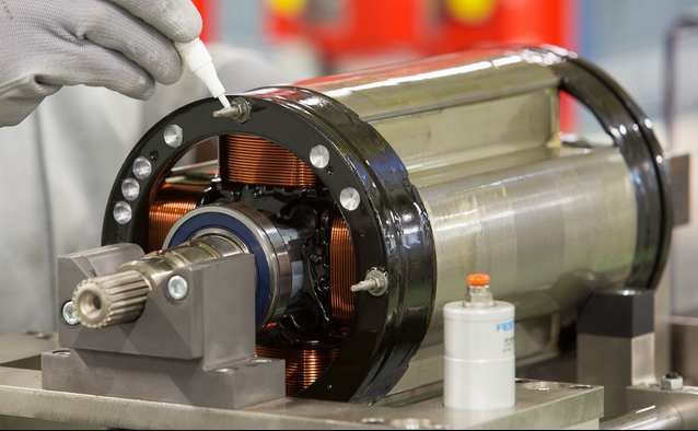
Choice of slot / pole combination

 •   However, NVH behaviour under forced excitation (far from any resonance) highly depends on the chosen
     combination of pole numbers / slot numbers / flux barrier numbers
 •   The higher the magnetic force wavenumber r, the lower is the resulting vibration due to larger yoke stiffness
 •   Typically in EV/HEV traction motors a force wavenumber r above 6 should not create significant noise

 •   SCIM: lowest positive magnetic force wavenumber is given by r min=GCD(Zs,Zr,2p) at partial load

                                                Effect of rotor slot number on maximum noise of an
                                                    induction motor using MANATEE® software                          9
       © EOMYS ENGINEERING 2013-2018   www.eomys.com
Choice of slot / pole combination

 •   PMSM: lowest positive magnetic force wavenumber is r min=GCD(Zs,2p) or GCD(Zs,2p)/2 at partial load
 •   To minimize the forced NVH behaviour of non pulsating (r>0) magnetic forces, GCD(Zs,2p) should be maximized
 •   rmin =1 should be avoided as it reveals the presence of an Unbalanced Magnetic Pull harmonic

                                                       r=1 force wavenumber

 •   WARNING: « large » rmin (typically above 6 for EV/HEV) is a sufficient but not necessary condition to lower
     forced e-NVH reponse – a low rmin can be reached with low magnitude slot / magnet harmonics

                          Quick NVH design of electrical machines using GCD rule is not recommended,
                          variable speed vibro-acoustic simulation using fast semi-analytic models is advised

       © EOMYS ENGINEERING 2013-2018   www.eomys.com                                                               10
Assymetries
• Eccentricities increase the spectral density of harmonic forces and transform pulsating forces (r=0) in
unbalanced magnetic pulls (r=+/-1)
• Uneven airgap also increases magnetic force harmonic contents, creating additional resonances
• The machine should be magnetically and geometrically symmetrical:
- low tolerance on eccentricities and misalignments
- low tolerance on lamination roundness
- low tolerance on magnet magnetization
- low tolerance on magnet position in slots
Effect of stator roundness on variable speed sound level using MANATEE®
software (left: circular stator, right: elliptical stator shape)
© EOMYS ENGINEERING 2013-2018 www.eomys.com 11Winding design
• The ideal winding gives a sinusoidal field, it corresponds to an infinite number of slot per pole per phase (no
« belt harmonics » and no « slot harmonics » or preferably no « step harmonics »)
• Concentrated winding / tooth-winding / fractional winding have the largest space harmonic distortion factor,
however if properly designed they can give low noise electric motors
• To avoid Unbalanced Magnetic Pull the armature field should never have 2 harmonics separated of 1
• Shorted-pitch distributed windings gives the smoothest field (coil pitch Y can be chosen as (5/6) Zs/(2p) slots
to reduce the stator mmf 5p and 7p harmonics)
Stator windings distribution (τ=1/1.2)
Stator windings distribution (τ=10/12) over 1/2 period
R
A
S
B
C T
0 0.05 0.1 0.15
0 0.05 0.1 0.15 0.2 0.25 0.3 mechanical position along airgap in trigonometric direction [m]
mechanical position along airgap in trigonometric direction [m]
Stator winding functions at t=0 s
Stator winding functions at t=0 s
4
A-phase WF 20 R-phase WF
2 B-phase WF S-phase WF
C-phase WF 0
0 T-phase WF
total mmf
-2 -20 total mmf
-4
0 0.5 1 1.5 2 2.5 3 0 1 2 3 4 5 6
mechanical angle αs [rad] mechanical angle αs [rad]
Winding harmonics analysed with MANATEE® software
(left: Zs=36 p=2 shorted-pitch distributed winding, right: Zs=12 p=5 concentrated winding )
© EOMYS ENGINEERING 2013-2018 www.eomys.com 12Skewing
• Skewing consists in rotating the stator or rotor 2D magnetic circuit along the axial direction of the
machine to filter out some annoying flux/force harmonics
SPMSM rotor IPMSM stator SCIM rotor
• Skewing does not always reduce NVH behaviour of electric powertrains:
- skewing introduces axial magnetic force variations which can excite « 3D » modes of the stator
- skewing introduces axial magnetic force ripple
- skewing can increase noise at some specific operating points and reduce noise at other operating
points
© EOMYS ENGINEERING 2013-2018 www.eomys.com 13Skewing
• Skewing always reduces fundamental torque - if current is increased to compensate torque
reduction, noise increase due to current increase is generally negligible (e.g. 5% current increase gives
0.4 to 0.8 dB increase)
• Skewing has no influence on PWM switching noise, only on « slotting PWM » or slotting harmonics
(e.g. pole/slot/armature interactions in PMSM, rotor to stator slot interactions in SCIM)
• Optimal skew to minimize noisy electromagnetic excitations is not always « one stator slot pitch »
Ex: IPMSM step skew to reduce open circuit pulsating (r=0) excitations:
• Optimal skewing pattern might be different when minimizing torque ripple or vibration and noise
due to electromagnetic forces
Variable speed vibro-acoustic simulation is advised
© EOMYS ENGINEERING 2013-2018 www.eomys.com 14Skewing
• Example of the skew optimization environment on a 2-step skewed IPMSM with MANATEE®
-Torque ripple reduction is not correlated to
noise reduction
- Optimal theoretical skew to cancel
pulsating force (0.5 slot pitch) successfully
reduces first resonance but increase noise
at other speeds
© EOMYS ENGINEERING 2013-2018 www.eomys.com 15Skewing
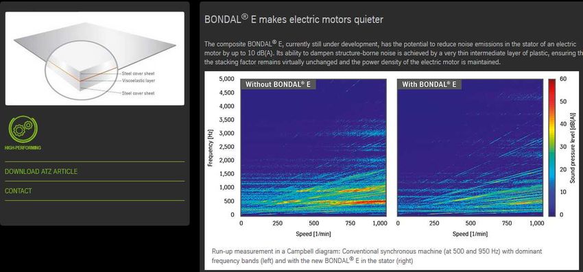
• Example of the skew optimization environment on a 2-step skewed IPMSM with MANATEE®
-Skewing can reduce or increase pulsating
forces depending on operating point
-Radial & tangential pulsating forces are
generally uncorrelated
© EOMYS ENGINEERING 2013-2018 www.eomys.com 16Pole shape, width and position
• Magnet / pole shoe shaping [D11] or shifting allows to modify the harmonic content of rotor field
excitation, and influence the electric motor NVH behaviour
• Optimal pole arc to pole width to reduce 0-th order radial and tangential open circuit forces (applicable to
both SPMSM and IPMSM) [D8, D9]
Nc =LCM(Zs,2p)
• More generally all rotor magnetomotive force harmonics multiple of k are removed if pole width is given
by (1-1/k)π/p
• Similarly to skewing, magnet shape optimization requires studying acoustic noise Vs torque ripple
minimization tradeoffs
© EOMYS ENGINEERING 2013-2018 www.eomys.com 17Slot shape, width and position
• Stator and rotor slot shapes or positions can be modulated to spread the permeance spatial spectrum or
reduce / cancel a specific harmonic involved in noise and vibration generation
• Stator slot opening can be chosen to minimize some specific force harmonics
due to stator permeance harmonics
Example of pulsating radial force at 6fs in a 6s4p SPMSM from MANATEE®:
[D33]
[D73]
© EOMYS ENGINEERING 2013-2018 www.eomys.com 18Notching
• Notches (circumferential slits / auxiliary slots) affect the airgap permeance harmonics and the
resulting magnetic force harmonics
• If properly sized, they can artificially increase the permeance wavenumber, as if the stator slot
number was increased
• The average airgap is increased due to notches (increase of Carter coefficient) so it may reduce
the electromagnetic performances
• Similarly to skewing, the effect of notches can strongly depend on the operating point
[D26]
[D50]
Use of rotor notch to mitigate acoustic noise
from MANATEE software®
© EOMYS ENGINEERING 2013-2018 www.eomys.com 19Control (PMSM)
• Id / Iq current angle or load angle has a strong influence on force harmonics, this influence depends on their
frequency and wavenumber [D12]
• Iq changes both the 0-th order radial and tangential force harmonics (torque) , Id changes only the 0-th order radial
force harmonics [D1] [D19][D20]
• In [D45] negative Id cancels the r=2 force wave due to slot/pole interaction in a Zs=12 p=5 SPMSM
but the technique is only effective at low Iq current
[D45]
[D55]
© EOMYS ENGINEERING 2013-2018 www.eomys.com 20Current injection (PMSM)
• A given electromagnetic vibration/noise harmonic can be damped by injecting additional harmonic currents
if its wavenumber can be generated by the armature field
• Due to quadratic nature of magnetic forces, current injection can also create parasitic force/vibration/noise
• Ex: Zs=60 p=5 LCM(Zs,2p)/p=12, the 12-th time harmonics of torque ripple (and r=0 radial pulsating force)
can be damped by harmonic current injection at 12 fs in Park frame
• For radial force damping either id or iq harmonic injection theoretically works, Id harmonic injection is
advised not to affect torque ripple [D19]
• Example of implementation in WRSM Zs=48 p=2 [D82]
© EOMYS ENGINEERING 2013-2018 www.eomys.com 21Current injection (PMSM)
• Control can also be used to cancel induced currents by back emf
• Example of implementation in a IPMSM Zs=60 p=5 [D87]
© EOMYS ENGINEERING 2013-2018 www.eomys.com 22Switching / commutation strategy
• Current harmonics (e.g. due to Pulse Width Modulation PWM) create additional harmonic forces
around multiples of the switching frequency fswi- mainly of wavenumber r=0 and r=2p
• For traction EV/HEV motors r=2p wavenumbers do not create significant noise so the pulsating
components r=0 are the remaining ones
Force level
2fs
fswi
Frequency [Hz]
2fswi+4fs
3fswi+fs
2fswi+6fs
3fswi+3fs
2fswi+2fs
3fswi-5fs
3fswi+5fs
3fswi-3fs
fswi+3fs
fswi+5fs
fswi+fs
2fswi-4fs
2fswi-6fs
fswi-5fs
fswi-fs
2fswi
fswi-3fs
3fswi-fs
2fswi-2fs
2fs
fswi : switching frequency [Hz]
fs : fundamental stator current frequency [Hz] r=0 r=2p
© EOMYS ENGINEERING 2013-2018 www.eomys.com 23Switching / commutation strategy
• To reduce PWM noise the swithing frequency must be optimized – no excitation of stator « breathing
mode », and ideally switching above 20 kHz to make switching harmonics inaudible
• Commutation strategy can be changed as a function of speed to avoid specific resonances
• To reduce PWM noise roughness some randomized PWM can be used
• Other techniques include phase shifting the carriers of a dual winding or [D88]
phase shifting three different carriers
[D89]
© EOMYS ENGINEERING 2013-2018 www.eomys.com 24Switching / commutation strategy
• Example of change of switching frequency using sound synthesis feature of MANATEE® software:
Sound under sine supply Sound with PWM 4800 Hz Sound with PWM 4800 Hz +/-
asynchronous switching 5% randomized switching
© EOMYS ENGINEERING 2013-2018 www.eomys.com 25Structural modifications
• Lower noise & vibration can be achieved by putting the natural frequencies further away from the excitations
• The yoke can be stiffened to reduce vibration and noise levels ; in this case one must check that the natural
frequency change does not create new resonances
• The m=0 circumferential order behaves differently compared to m>1
Frequency variation of m=0 mode
6500
6000
5500
Frequency [Hz]
5000
4500
4000 Stator mode (0,0) « breathing mode »
3500
natural frequency
3000
2500
2000
0 10 20 30 40 50 60 70 80 90 100
Stator yoke [mm]
© EOMYS ENGINEERING 2013-2018 www.eomys.com 26• Example of shape study automatically run with MANATEE® software:
• Other structural changes include playing on lamination frame/coupling or yoke geometry
[D32] [D31] [D66]
© EOMYS ENGINEERING 2013-2018 www.eomys.com 27Damping
• Increasing damping is a very efficient way of reducing vibration and noise
• Damping of electric motors mainly comes from winding insulation and resin to the impregnation of
the machine should be optimized (curing cycle, resin type, impregnation type)
• Other techniques include the use of higher magnetic sheets (lower stacking factor)
[D67]
© EOMYS ENGINEERING 2013-2018 www.eomys.com 28Miscellaneous noise and vibration reduction techniques
• Shifted rotor laminations used in SRM distribute the radial force along axial
direction and reduce vibrations [D71]
• Use of GO steel with shifted orientation along axis also reduce noise and
vibrations (but it is more expensive compared to NGO)
• Shifting lamination along axial direction to reduce radial force component [D72]
• Passive damping using auxiliary winding
• Active control and reduction of back-emf induced current harmonics
• Passive or active piezoelectric actuators
© EOMYS ENGINEERING 2013-2018 www.eomys.com 29Conclusions
• There is no simple electromagnetic noise control technique and no general « recipe » / formula for low noise
electric motor
• Noise mitigation techniques to be implemented depend on electric motor topology
• Large e-NVH reduction can be achieved (up to 40 dB) after having identified the root cause of noise (flux
harmonic combination)
• There exist strong tradeoffs to do between electromagnetic & NVH performances
• Vibroacoustic behaviour of electric powertrain should be evaluated during early electromagnetic design phase
• Variable speed electromagnetic & vibro-acoustic simulation is always needed – but not with full numerical
models, semi analytic models are recommended to reduce calculation time and parasitic numerical noise
Thank you for your attention
Any questions ?
“e-NVH academy” resources: https://eomys.com/e-nvh/
MANATEE® trial version: www.manatee-software.com
© EOMYS ENGINEERING 2013-2018 www.eomys.com 30These references come from EOMYS dedicated technical training on e-NVH, see eomys.com
[D1] W. Zhu, S. Pekarek, B. Fahimi, S. Member, B. J. Deken, and S. Member, “Investigation of Force Generation in a Permanent Magnet Synchronous Machine,” vol. 22, no. 3, pp. 557–565, 2007.
[D2] T. Heikkilä., « Permanent magnet synchronous motor for industrial inverter applications - analysis and design », Thèse de l'Université de Technologie de Lappeenranta, 2002
[D3] ZHU (Z.Q.), MOHD JAMIL (M.L.) et WU (L.J.), Influence of Slot and Pole Number Combinations on Unbalanced Magnetic Force in Permanent Magnet Machines, IEEE
[D4] J. LE BESNERAIS, “Reduction of audible magnetic noise in PWM-supplied induction machines”, PhD thesis, 2008
[D5] ZHU (Z.Q.), XIA (Z.P.), WU (L.J.), et JEWELL (G.W.), Influence of slot and pole number combination on radial force and vibration modes in fractional slot PM brushless machines having single- and
double-layer windings, in Proc. IEEE ECCE, San Jose, CA, Sep. 20–24, 2009, pp. 3443–3450.
[D6] ZHU (Z.Q.), MOHD JAMIL (M.L.) et WU (L.J.), Influence of Slot and Pole Number Combinations on Unbalanced Magnetic Force in Permanent Magnet Machines, IEEE
[D7] HWANG (S.M.), EOM (J.B.), HWANG (G.B.), JEONG (W.B.) et JUNG (Y.H.), Cogging torque and acoustic noise reduction in permanent magnet motors in teeth pairing, IEEE Trans. on Mag, Vol 36,
No 5, 2000
[D8] Zhu, Z.Q.; Ruangsinchaiwanich, S.; Schofield, N.; Howe, D., "Reduction of cogging torque in interior-magnet brushless machines," Magnetics, IEEE Transactions on , vol.39, no.5, pp.3238,3240,
Sept. 2003
[D9] J. LE BESNERAIS, “Vibroacoustic analysis of radial and tangential force harmonics in PMSM”, IEEE Trans on Mag, 2014
[D10] A. Rahideh, M. Mardaneh, and T. Korakianitis, “Analytical 2D Calculations of Torque , Inductance and Back- EMF for Brushless Slotless Machines with Surface Inset Magnets,” no. c, 2013.
[D11] A. Frias, P. Pellerey et al. “Rotor and Stator Shape Optimization of a Synchronous Machine to Reduce Iron Losses and Acoustic Noise.” In Proc of the 8th IEEE Vehicle Power and Propulsion
Conference (VPPC'2012), Séoul : Corée, République De (2012).
[D12] ZHU (L.), JIANG (S.Z.), ZHU (Z.Q.) et CHAN (C.C.), Analytical Methods for Minimizing Cogging Torque in Permanent-Magnet Machines, IEEE Trans. on Mag, Vol 45, No 4, 2009
[D13] GIERAS (J. F.), CHO LAI (J.) et WANG (C.), Noise of polyphase electric motors, CRC Press, 2006.
[D14] P. Pellerey, V. Lanfranchi, G. Friedrich, and A. E. Characterization, “Influence of the load angle on the magnetic pressure harmonic content of a WRSM,” pp. 877–882, 2010.
[D15] J. LE BESNERAIS, P. PELLEREY, V. LANFRANCHI and M. HECQUET, Bruit acoustique d’origine magnétique dans les machines synchrones (in French), Techniques de l’Ingénieur, 2014
[D16] Liang W. et al, Analytical investigation of sidebad electromagnetic noise in PMWM drive with voltage-source oinverter by SVPWM technique, IEEE Trans on En Conv 2014
[D17} Dorrell, D.G.; Smith, AC., "Calculation of UMP in induction motors with series or parallel winding connections," Energy Conversion, IEEE Transactions on , vol.9, no.2, pp.304,310, Jun 1994
[D18] Investigation on a choice of stator slot skew angle in brushless PM machines, M. Jagiela et al., Electrical Engineering Journal, Oct 2012
[D19] Modeling and control of radial forces due to electromagnetic force in IPMSMs, M. Kanematsu et al, EVTeC, 2014
[D20] Field weakening for radial force reduction in brushes permanent-magnet DC motors, G. Jiao et al, IEEE Trans on Mag, 2004
[D21] Motors with buried magnets for medium speed application, J. Kolehmainen, IEEE Trans on En Conv, 2008
[D22] Torque Ripple Improvement for Synchronous Reluctance Motor Using an Asymmetric Flux Barrier Arrangement, M Sanada et al, IEEE Trans on Ind Appl, 2004
[D23] Influence of the Number of Pole Pairs on the Audible Noise of Inverter-Fed Electric Motors: Radial Force Waves and Mechanical Resonances, I Tsoumas, ICEM 2014
[D24] B. Cassoret, J-Ph. Lecointe et J-F. Brudny. “Influence of the pole number on the magnetic noise of electrical AC machines”. Dans : Progress In Electromagnetics Research (B) 33 (2011), p. 83–97
[D25] C. Schlensok and G. Henneberger, “Torque behaviour in induction machines due to skewing.”
[D26] Guy Won Cho, « The Optimal Design of Fractional-slot SPM to Reduce Cogging Torque and Vibration”
[D27] N Bianchi, « Design Techniques for Reducing the Cogging Torque in Surface-Mounted PM Motors” 2002
[D28] W. Fei, « A New Technique of Cogging Torque Suppression in Direct-Drive Permanent Magnet Brushless Machines”
[D29] S. M. Hwang « Cogging torque and acoustic noise reduction in permanent magnet motors by teeth pairing
[D30] S. Qurban, A. Shah, T. A. Lipo, L. Fellow, and B. Kwon, “Modeling of Novel Permanent Magnet Pole Shape SPM Motor for Reducing Torque Pulsation,” vol. 48, no. 11, pp. 4626–4629, 2012.”
[D31] L. Durantay, F. Laurent, Y. Messin, B. Interface, L. Durantay, F. Laurent, Y. Messin, and V. Kromer, “Large-band reduction of magnetic vibrations of induction machines with breaking-of-impedance
interface,” IEEE Trans. Ind. Appl., vol. 36, no. 4, pp. 1126–1131, 2000.
[D32] C. Schlensok, M. Van Der Giet, M. H. Gracia, D. Van Riesen, and K. Hameyer, “Structure-Dynamic Analysis of an Induction Machine Depending on Stator–Housing Coupling,”
IEEE Trans. Ind. Appl., vol. 44, no. 3, 2008.
[D33] RATHNA KUMAR SASTRY CHITROJU Improved Performance Characteristics of Induction Machines with Non-Skewed Asymmetrical Rotor Slots. 2009.
© EOMYS ENGINEERING 2013-2018 www.eomys.com 31[D34] A. Stening, Analysis and Reduction of Parasitic Effects in Induction Motors With Die-Cast Rotors 2013.
[D35] Daohan Wang; Xiuhe Wang; Dongwei Qiao; Ying Pei; Sang-Yong Jung, "Reducing Cogging Torque in Surface-Mounted Permanent-Magnet Motors by Nonuniformly Distributed Teeth Method," in
Magnetics, IEEE Transactions on , vol.47, no.9, pp.2231-2239, Sept. 2011
[D36] M. J. DeBortoli, S. J. Salon, D. W. Burow, and C. J. Slavik, “Effects of rotor eccentricity and parallel windings on induction machine behavior: a study using finite element analysis”, IEEE Trans. on
Mag., Vol. 29, No. 2, pp. 1676-1682, March 1993.
[D37] A. Tenhunen, “Finite-element calculation of unbalanced magnetic pull and circulating current between parallel windings in induction motor with non-uniform eccentric rotor”, Proceedings of
Electromotion’01. Bologna, Italy, 19-20 June 2001, pages 19-24.
[D38] Jung-Pyo Hong, Kyung-Ho Ha, and Ju Lee. Stator pole and yoke design for vibration reduction of switched reluctance motor. Magnetics, IEEE Transactions on, 38(2) :929–932, mars 2002.
[D39] D. Torregrossa, F. Peyraut, M. Cirrincione, C. Espanet, A. Cassat, and A. Miraoui. A new passive methodology for reducing the noise in electrical machines : Impact of some parameters on the
modal analysis. Industry Applications, IEEE Transactions on, 46(5) :1899 –1907, sept. - oct. 2010. 52
[D40] Anthony Frias, Pierre Pellerey, Afef Kedous-Lebouc, Christian Chillet, Vincent Lanfranchi, Laurent Albert, and Louis Humbert. Rotor and stator shape optimization of a synchronous machine to
reduce iron losses and acoustic noise. In The 8th IEEE Vehicle Power and Propulsion Conference (VPPC’ 2012), pages 98–103, Séoul, Corée, République De, 2012
[D41] Application of Sinusoidal Field Pole in a Permanent-Magnet Synchronous Machine to Improve the NVH Behavior Considering the MTPA and MTPV Operation Area
[D42] D. Macintosh, Skewing For Both Cogging Torque Components In Permanent Magnet Machines
[D43] Modelling framework for electromagnetic noise generation from traction motors F. Botling
[D44] T. Lugand, “Contribution to the Modeling and Optimization of the Double-Fed Induction Machine for Pumped-Storage Hydro Power Plant Applications,” Ph.D. dissertation, Grenoble University,
Grenoble, France, 2013.
[D45] Proposal of Vibration Control Reducing 2nd Radial Electromagnetic Force, EEJ
[D46] A. Wanke et al “Performance invariant noise reduction of a plug-in hybrid electric drive using an innovative skewing concept”, InterNoise 2016
[D47] Rajah Singh, “Energy Saving Strategy on Electric Propulsion System Integrated with Doubly Fed Asynchronous Motors”
[D48] D. Franck, “Active reduction of audible noise exciting radial force-density waves in induction motors”, 2011
[D49] Cassoret, B., Corton, R., Roger, D., & Brudny, J. (2003). Magnetic Noise Reduction of Induction Machines, 18(2), 570–579.
[D50] Gui-Yu Zhou and J-X Shen, “Rotor Notching for Electromagnetic Noise Reduction of Induction Motors”, IEEE Trans Mag 2016
[D51] Gilson, A., Verez, G., Dubas, F., Depernet, D., & Espanet, C. (n.d.). Design of a High-Speed Permanent-Magnet Machine for Electrically-Assisted Turbocharger Applications with Reduced Noise
Emissions.
[D52] S. J. Sung, G. H. Jang and H. J. Lee, "Torque Ripple and Unbalanced Magnetic Force of a BLDC Motor due to the Connecting Wire Between Slot Windings," in IEEE Transactions on Magnetics, vol.
48, no. 11, pp. 3319-3322, Nov. 2012.doi: 10.1109/TMAG.2012.2198879
[D53] Guandong Jiao and C. D. Rahn, "Field weakening for radial force reduction in brushless permanent-magnet DC motors," in IEEE Transactions on Magnetics, vol. 40, no. 5, pp. 3286-3292, Sept.
2004.doi: 10.1109/TMAG.2004.832989
[D54] D. Y. Kim, G. H. Jang and J. K. Nam, "Magnetically Induced Vibrations in an IPM Motor Due to Distorted Magnetic Forces Arising From Flux Weakening Control," in IEEE Transactions on
Magnetics, vol. 49, no. 7, pp. 3929-3932, July 2013. doi: 10.1109/TMAG.2013.2238614
[D55] Valavi, Mostafa; Pascal, Jules; Nysveen, Arne. (2016) Analysis of Radial Magnetic Forces in Hydrogenerators with Fractional-Slot Windings. 2016 XXII International Conference on Electrical
Machines (ICEM 2016)Conference Proceedings.
[D56] Jiang, Weisheng; et al, Noise and Vibration Reduction for IPMSM by Using Rotor Circumferential Slits
[D57] G. J. Park, Y. J. Kim and S. Y. Jung, "Design of IPMSM Applying V-Shape Skew Considering Axial Force Distribution and Performance Characteristics According to the Rotating Direction," in IEEE
Transactions on Applied Superconductivity, vol. 26, no. 4, pp. 1-5, June 2016.
doi: 10.1109/TASC.2016.2543267
[D58] W. Fei, Comparison of Cogging Torque Reduction in Permanent Magnet Brushless Machines by Conventional and Herringbone Skewing Techniques
[D59] D. Dinca, Circulating currents of delta connected fractional slot machines for mass production
[D60] Besnerais, J. Le, Lanfranchi, V., Hecquet, M., Romary, R., & Brochet, P. (2009). Optimal Slot Opening Width for Magnetic Noise Reduction in Induction Motors. IEEE Transactions on Energy
Conversion. http://doi.org/10.1109/tec.2009.2025421
© EOMYS ENGINEERING 2013-2018 www.eomys.com 32[D61] H. Guldemir, K. J. Bradley (2001) The Effect of Rotor Design on Rotor Slot Harmonics in Induction Machines, Electric Power Components and Systems,
29:9, 771-788, DOI: 10.1080/153250001317094199
[D62] S. Zuo, F. Lin and X. Wu, "Noise Analysis, Calculation, and Reduction of External Rotor Permanent-Magnet Synchronous Motor," in IEEE Transactions on Industrial Electronics, vol. 62, no. 10, pp.
6204-6212, Oct. 2015.
[D63] Vibroacoustic optimization of permanent magnet synchronous motor, Journal Sound Vibrations, 2017
[D64] M. Sanada, K. Hiramoto, S. Morimoto and Y. Takeda, "Torque ripple improvement for synchronous reluctance motor using an asymmetric flux barrier arrangement," in IEEE Transactions on
Industry Applications, vol. 40, no. 4, pp. 1076-1082, July-Aug. 2004. doi: 10.1109/TIA.2004.830745
[D65] P. O. Rasmussen, J. Andreasen, and J. M. Pijanowski, “Structural Stator Spacers-the Key to Silent Electrical Machines,” Thirty-Sixth IAS Annu. Meet. Conf. Rec. 2001 IEEE Ind. Appl. Conf., vol. 1, no. C, pp. 33–39, 2001.
[D66] K. Masoudi, M. R. Feyzi, and A. Masoudi, “Reduction of Vibration and Acoustic Noise in the Switched Reluctance Motor by Using New Improved Stator Yoke Shape,” in 2013 21st Iranian
Conference on Electrical Engineering (ICEE), 2013, pp. 1–4.
[D67] P. O. Rasmussen, E. C. LaBrush, and J. H. Andreasen, “Interlaminated Damping - A Method for Reduction of Vibration and Acoustic Noise for Switched Reluctance Machines,” Conf. Rec. - IAS
Annu. Meet. (IEEE Ind. Appl. Soc., vol. 3, pp. 1531–1539, 2005.
[D68] J. Li and Y. Cho, “Dynamic Reduction of Unbalanced Magnetic Force and Vibration in Switched Reluctance Motor by the Parallel Paths in Windings,” Math. Comput. Simul., vol. 81, no. 2, pp. 407–
419, 2010.
[D69] A. Sakuma, M. Kadowaki, H. Ukigai, I. Miki, T. Okamoto, and T. Segawa, “Stator Structure for Noise Reduction of Switched Reluctance Motor,” Electr. Mach. Syst. (ICEMS), 2012 15th Int. Conf., pp.
1–4, 2012
[D70] Dajaku, “Analysis of Different PM Machines with Concentrated Windings and Flux Barriers in Stator Core”
[D71] J. H. Oh and Byung Il Kwon, “New rotor shape design of SRM to reduce the torque ripple and improve the output power,” 2005 Int. Conf. Electr. Mach. Syst., vol. 1, p. 652–654 Vol. 1, 2005.
[D72] P. O. Rasmussen, F. Blaabjerg, J. K. Pedersen, and F. Jensen, “Switched Reluctance-Shark Machines-More Torque and Less Acoustic Noise,” Conf. Rec. 2000 IEEE Ind. Appl. Conf., vol. 1, pp. 93–
98 vol.1, 2000.
[D73] Khwaja Rahman, “Retrospective of Electric Machines for EV and HEV Traction Applications at General Motors”, IEEE Trans. On Magnetics, 2016
[D74] Unbalanced Magnetic Force Mitigation in 3-slot/2- pole Permanent Magnet Machine by Inserting Auxiliary Slots
[D75] Hoadong Yang, Electromagnetic Vibration of Interior Permanent Magnet Brushless Motors under Brushless DC and AC Operation
[D76] B. Iamamura, M. Rossi, M. Hecquet, V. Lanfranchi, S. Recorbet, and F. Tridon, “Vibration and acoustic noise of industrial inductors associated to converters in railway domain: design and material
impacts,” ISEF 2015 - XVII Int. Symp. Electromagn. Fields Mechatronics, Electr. Electron. Eng., 2015.
[D77] E. Baba, R. Oka, Y. Suzuki, Y. Kawase, and M. Tatsuno, “Reactor Vibration Analysis in Consideration of Coupling between the Magnetic Field and Vibration,” Industry Applications Conference,
2004. 39th IAS Annual Meeting. Conference Record of the 2004 IEEE, 2004, pp. 872-877 vol.2.
[D78] Y. Gao, K. Muramatsu, M. Hatim, K. Fujiwara, Y. Ishihara, S. Fukuchi, and T. Takahata, “Design of a reactor driven by inverter power supply to reduce the noise considering electromagnetism and
magnetostriction,” IEEE Transactions on Magnetics, vol. 46, no. 6, pp. 2179–2182, June 2010
[D79] G. Terorde, J. Schneider, and K. Hameyer, “Investigations of the audible
noise of inductors with respect to different ferromagnetic materials,” COMPEL: The International Journal for Computation and Mathematics in Electrical and Electronic Engineering, vol. 18, no. 4, pp.
647–655, 1999.
[D80] Yusuf Yasa, Acoustic Noise Mitigation for High Pole Count Switched Reluctance Machines through Skewing Method with Multiphysics FEA Simulations, ECCE 2017
[D81] Effect of Distributed Airgap in the Stator for Acoustic Noise Reduction in Switched Reluctance Motors
[D82] P. Pellerey, “Active Reduction of Electrical Machines Magnetic Noise by the Control of Low Frequency Current Harmonics.”
[D83] R. Islam, I. Husain, A. Fardoun and K. McLaughlin, "Permanent-Magnet Synchronous Motor Magnet Designs With Skewing for Torque Ripple and Cogging Torque Reduction," in IEEE Transactions
on Industry Applications, vol. 45, no. 1, pp. 152-160, Jan.-feb. 2009.
[D84] X. Ge, Z. Q. Zhu, G. Kemp, D. Moule and C. Williams, "Optimal Step-Skew Methods for Cogging Torque Reduction Accounting for Three-Dimensional Effect of Interior Permanent Magnet
Machines," in IEEE Transactions on Energy Conversion, vol. 32, no. 1, pp. 222-232, March 2017.
[D85] “Torque Ripple Reduction of IPMSM Applying Asymmetric Rotor Shape Under Certain Load Condition”
© EOMYS ENGINEERING 2013-2018 www.eomys.com 33[D86] Rick, S., Putri, A. K., Franck, D., & Hameyer, K. (2016). Hybrid Acoustic Model of Electric Vehicles: Force Excitation in Permanent-Magnet Synchronous Machines. Ieee Transactions on Industry
Applications, 52(4), 2979–2987. http://doi.org/10.1109/TIA.2016.2547360
[D87] Boesing, « Acoustic modeling of electrical drives - noise and vibration synthesis based on force response superposition”, RWTH University, Aachen, 2013
[D88] X. Han, D. Jiang, T. Zou, R. Qu and K. Yang, "Two-Segment Three-phase PMSM Drive with Carrier Phase-shift PWM for Torque Ripple and Vibration Reduction," in IEEE Transactions on Power
Electronics, 2018.
[D89] T. SZKUDLAPSKI et al, “AC rotating machine radial vibrations: a principle to reduce the PWM switching effects”, 2015
[D90] J. Blum, J. Merwerth and H. G. Herzog, "Investigation of the segment order in step-skewed synchronous machines on noise and vibration," 2014 4th International Electric Drives Production
Conference (EDPC), Nuremberg, 2014, pp. 1-6.
[D91] J. Le Besnerais, C. Dendiviel, M. Régniez, P. Boussard, “Sound quality optimization of electric powertrains for e-mobility applications”, French Congress on Acoustics, April 2018
© EOMYS ENGINEERING 2013-2018 www.eomys.com 34You can also read