Energy Storage Safety Strategic Plan - U.S. Department of Energy Office of Electricity Delivery and Energy Reliability
←
→
Page content transcription
If your browser does not render page correctly, please read the page content below
Energy Storage Safety
          Strategic Plan

                U.S. Department of Energy

    Office of Electricity Delivery and Energy Reliability
                        December, 2014

1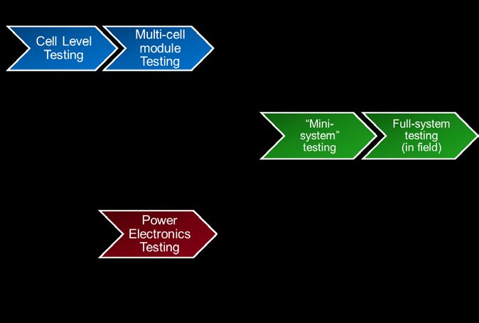
Acknowledgements

The Department of Energy Office of Electricity Delivery and Energy Reliability would like to
acknowledge those who participated in the 2014 DOE OE Workshop for Grid Energy Storage
Safety (Appendix A), as well as the core team dedicated to developing this report to address the
safety of grid energy storage systems: Sean J. Hearne, Summer Ferreira, Mark Smith, Abbas
Akhil & Amanda Spinney (Sandia National Laboratories); Landis Kannberg, Vincent Sprenkle,
& David Conover (Pacific Northwest National Laboratory); Matthew Paiss (International
Association of Fire Fighters); Michael A. Stosser (Sutherland Asbill & Brennan LLP); Robert S.
Fleishman (Morrison & Foerster LLP).

Additionally, the Department of Energy Office of Electricity Delivery and Energy Reliability
would like to acknowledge the generous efforts made to review the document from all the
members of the 2014 DOE OE Workshop for Grid Energy Storage Safety (Appendix A), the
members of the EPRI ESIC Working Group 3, and specifically Ken Willette (National Fire
Protection Agency), Ryan Franks (National Electrical Manufacturers Association), Dean E.
Philips & Conrad Eustis (Electric Power Research Institute), Jim Arseneaux (Beacon Power,
LLC), Davion Hill (DNV-GL), Hiroyuki Kubo (Incorporated Administrative Agency, National
Institute of Technology and Evaluation of Japan), and Nanamori Yasuyuki (Mitsubishi Research
Institute, Inc.).

Dr. Imre Gyuk
Program Manager
Energy Storage Research
Office of Electricity Delivery and Energy Reliability
U.S. Dept. of Energy

2
Contents
    Acknowledgements ..................................................................................................................... 2

    Executive Summary .................................................................................................................... 6

       Science-based Safety Validation Techniques: ......................................................................... 8

       Incident Preparedness: ............................................................................................................. 9

       Safety Documentation: ............................................................................................................ 9

    1.0      Introduction and Motivation........................................................................................... 10

    2.0      Current State of Energy Storage Technologies .............................................................. 12

       2.1 Pumped Hydro Storage .................................................................................................... 13

       2.2 Compressed Air Energy Storage (CAES) ....................................................................... 13

       2.3 Superconducting Magnetic Energy Storage (SMES) ...................................................... 14

       2.4 Flywheels ......................................................................................................................... 14

       2.5 Capacitors ........................................................................................................................ 14

       2.6 Batteries ........................................................................................................................... 15

    3.0      State of Safety Validation in the U.S. ............................................................................ 15

    4.0      Key Aspects for Addressing Energy Storage Safety...................................................... 18

    5.0      Validation Techniques.................................................................................................... 19

       5.1 Current Validation Techniques ........................................................................................ 19

       5.2 Areas of Interest in Safety Validation ............................................................................. 21

       5.3 Materials Science R&D ................................................................................................... 23

       5.4 Electrolyte Safety R&D ................................................................................................... 25

       5.5 Engineering controls and system design ......................................................................... 30

       5.6 Testing and Analysis ....................................................................................................... 32

       5.7 Modeling.......................................................................................................................... 34

       5.8 Summary.......................................................................................................................... 41

3
6.0 Incident Preparedness ..................................................................................................... 41
6.1 Current Conditions .......................................................................................................... 41
6.2 Incident Preparedness ...................................................................................................... 43
6.3 Incident Response ............................................................................................................ 46
6.4 Gap Areas ........................................................................................................................ 47
7.0 Safety Documentation .................................................................................................... 50
7.1 Overview of the CSR Deployment Process and Involved Stakeholders ......................... 52
7.2 Compliance with Land Use Permitting and Environmental Requirements ..................... 57
7.3 Legal Framework for Energy Storage System Safety ..................................................... 60
8.0 Implementation of Goals to Reach Desired End States ................................................. 63
8.1 ESS Safety Technology .............................................................................................. 65
8.2 Risk Assessment and Management ............................................................................ 66
8.3 Incident Response ....................................................................................................... 67
8.4 Codes, Standards and Regulations.............................................................................. 68
Appendix ................................................................................................................................... 70
A. List of DOE OE Energy Storage Safety Workshop Participants and Affiliations ..... 70
B. Abridged List of Relevant Codes, Standards and Regulations ................................... 73
C. References for Validation Techniques ....................................................................... 75
Acronym List............................................................................................................................. 78
4Table of Figures
Figure 1. Percentage of Energy Storage Systems Deployed......................................................... 11
Figure 2. Maturity of Electricity Storage Technologies ............................................................... 13
Figure 3. Example of Possible Testing Arrangement for a Battery-Based Storage Product ........ 35
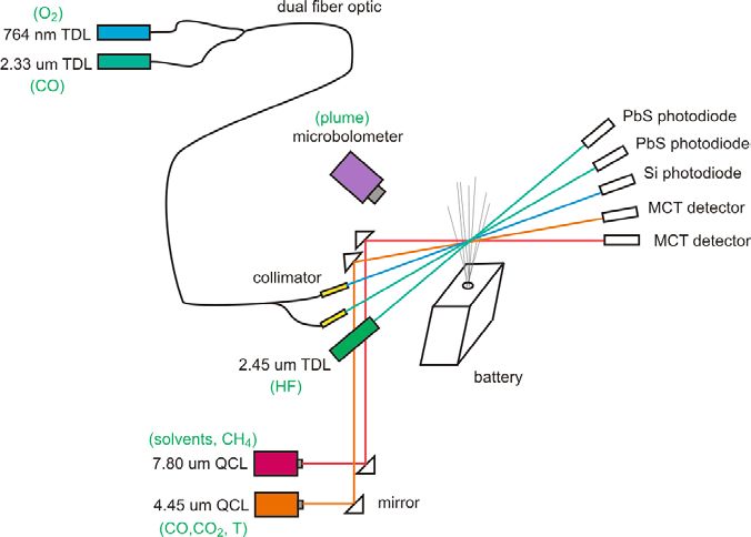
Figure 4. Experimental Setup of Gas Evolution and Release with Infrared Absorption .............. 36
Tables
Table 1. Range of Storage Technology and Size ...........................Error! Bookmark not defined.
Table 2. Common Tests to Assess Risk from Electrical, Mechanical, and Environmental
Conditions ...................................................................................................................... 31
Table 3. Tests under Development for Specific Technologies ..................................................... 38
5Executive Summary Energy storage is emerging as an integral component to a resilient and efficient grid through a diverse array of potential application. The evolution of the grid that is currently underway will result in a greater need for services best provided by energy storage, including energy management, backup power, load leveling, frequency regulation, voltage support, and grid stabilization. 1 The increase in demand for specialized services will further drive energy storage research to produce systems with greater efficiency at a lower cost, which will lead to an influx of energy storage deployment across the country. To enable the success of these increased deployments of a wide variety of storage technologies, safety must be instilled within the energy storage community at every level and in a way that meets the need of every stakeholder. In 2013, the U.S. Department of Energy released the Grid Energy Storage Strategy 2, which identified four challenges related to the widespread deployment of energy storage. The second of these challenges, the validation of energy storage safety and reliability, has recently garnered significant attention from the energy storage community at large. 3 This focus on safety must be immediately ensured to enable the success of the burgeoning energy storage industry, whereby community confidence that human life and property not be adversely affected is instilled from the earliest stages. 4 The resultant increase in consumer confidence in energy storage will ease and facilitate the expansion of energy storage’s deployment, allowing for the electric grid to meet the ever-expanding needs of the consumer. The safe application and use of energy storage technology knows no bounds. An energy storage system (ESS) will react to an external event, such as a seismic occurrence, regardless of its location in relation to the meter or the grid. Similarly, an incident triggered by an ESS, such as a fire, is ‘blind’ as to the location of the ESS in relation to the meter. This document will address grid-side safety, while recognizing that the efforts undertaken will apply to other ESS applications, regardless of deployment location. 1 Grid Energy Storage Strategy. U.S. Department of Energy, Dec. 2013. 2 Grid Energy Storage Strategy. U.S. Department of Energy, Dec. 2013, p. 5. 3 DOE OE Energy Storage Safety Workshop, Albuquerque, NM. 2014. 4 Gyuk, Imre. “Energy Storage Safety: An Essential Concern.” DOE OE Energy Storage Safety Workshop, Feb. 2014. 6
Each stakeholder group has a specific motivation for pursuing energy storage safety.
Manufacturers are producing an increasing number of systems and system components to meet a
growing demand for energy storage and must be confident in the safety of these products.
Regulators are required to address the system installations in terms of application space,
ownership, risk, and potential litigation. Insurers must develop applicable risk assessments and
first responders must be able to safely and successfully respond to any incidents.

The actions, responsibilities, and concerns of each stakeholder group are all interconnected. The
science-based techniques used to validate the safety of energy storage systems must be
documented a relevant way, that includes every level of the system and every type of system.
These science-based safety validation techniques will be used by each stakeholder group to
ensure the safety of each new energy storage system deployed onto the grid. Once researchers
establish science-based validation and mitigation techniques, manufacturers will have guidelines
that support the construction of systems that can be validated as safe. With standardized
guidelines for safe component and system construction, regulators and insurance companies will
be able to fully assess the risk of owning and insuring each system. Additionally, first
responders must be included in the discussion to ensure that all areas of potential failure are
identified and the best mitigation strategies are developed, spanning the chemistries and
materials choices through components, module layouts and deployment.

Safety of any new technology can be broadly viewed as having three intimately-linked
components: 1) a system must be engineered and validated to the highest level of safety possible;
2) techniques and processes must be developed for responding to incidences if they do occur;
and 3) the best practices and system requirements must then be reflected standardized safety
determinations in the form of codes, standards and regulations (CSR) so that there is uniform,
written guidance for the community to follow when designing, building, testing and deploying
the system. When successful, CSRs apply the best-known practices for safety to a system. The
predictability of real-time operation, and therefore safety, is improved when systems are
designed with similar system requirements.

A thread of complexity running through all three of the components of safety (i.e. validation
techniques, incident response and safety documentation) is an ever increasingly diverse portfolio
of technologies and the wide array of potential deployment environments. To provide the

7
greatest impact, the validation techniques discussion presented in this document focuses
primarily on batteries, with some discussion of flywheels, as these two technologies are
undergoing rapid evolution and growth in the deployment.

Safety documentation provides guidance to the energy storage community in the form of codes,
standards, and regulations. Two crucial considerations must be taken into account surrounding
the adoption and administration of standards. First, system owners must understand which codes
and standards are necessary before and after the installation of energy storage systems. Second,
the parties responsible for the oversight, regulation and response must be identified. This
identification will ensure a clear path of communication between owners, regulators and
responders to best prevent any potential incident. Both of these considerations will make the
installation process efficient and cost effective for owners, ensure that all responsible parties are
communicating to best avoid an incident, and ensure effective incident response. They will also
clearly outline risk, which will enable the application of effective risk mitigation and risk
management measures. These safety documents will be informed by the science-based
validation techniques established through research and development. This work will provide the
basis for the protocols and design in the codes and standards and will meet the needs to minimize
loss and protect the first responders.

The goal of this DOE Office of Electricity Delivery and Energy Reliability (OE) Strategic Plan
for Energy Storage Safety is to develop a high-level roadmap to enable the safe deployment
energy storage by identifying the current state and desired future state of energy storage safety.
To that end, three interconnected areas are discussed within this document:

Science-based Safety Validation Techniques:
    •   Most of the current validation techniques that have been developed to address energy
        storage safety concerns have been motivated by the electric vehicle community, and are
        primarily focused on Li-ion chemistry and derived via empirical testing of systems.
        Additionally, techniques for Pb-acid batteries have been established, but must be revised
        to incorporate chemistry changes within the new technologies. Moving forward, all
        validation techniques must be expanded to encompass grid-scale energy storage systems,
        be relevant to the internal chemistries of each new storage system and have technical
        bases rooted in a fundamental-scientific understanding of the mechanistic responses of

8
the materials. Experimental research and development efforts to inform models from cell
to system scale must be the basis of the next generation of validation techniques needed
for the new grid-scale storage systems, as empirically derived tests are not sufficient to
ensure safety.
Incident Preparedness:
• First responders will be called upon to respond to an incident should it occur to protect
the lives of anyone involved and minimize the damage to assists. Therefore, there must
be a deliberate and concerted effort to engage the first responder community early in the
design and siting of energy storage systems so that proper mitigation techniques can be
developed and systems designed to improve the overall safety and ability to quickly and
safety resolve the incident. This must include the development of techniques to
extinguish any fires if they were to occur and respond to the variety of non-fire incidents
that may require fire department response, developing site specific training for first
responders, improved systems design, and the development of incident response plans.
All of these must be based on the scientific understanding of the systems, materials and
processes and embodied in the criteria in codes, standards and regulations.
Safety Documentation:
• Currently, safety-related criteria in the form of codes, standards and regulations that
apply to system components and deployments need to be updated to reflect the growing
verity of storage technologies. This documentation is not specific to the multitude of
chemistries and assembled modules that compose the new storage systems being
deployed. As a result, CSR are inefficient and ineffective and must be updated and
standardized.
This document additionally highlights four key elements around which DOE efforts will revolve.
DOE programmatic efforts will focus on four elements:
• ESS safety technology
• Risk assessment and management
• Incident response
9• Codes, standards and regulations To ensure the thorough establishment of the scientific and technical basis for ESS safety in each technology, information concerning all safety hazards must be gathered and categorized. Testing and analysis procedures will then be defined in such a way that enables stakeholders to use them for each major class of ESS. Within risk assessment and management, the goal is that the framework and methodologies for assessing and managing deployment risk for ESS are accepted and adopted by industrial and regulatory stakeholders. Towards this end, current frameworks will be catalogued, and a model risk framework will be identified for specific ESS technologies. The ultimate goal for first and second responders is the complete awareness of hazards and the ability to address them in the field. Finally, it is the goal that codes, standards and regulations enable the deployment of safe ESS. Gaps in CSR that require additional technical research, development, and demonstration will be identified and addressed. 1.0 Introduction and Motivation Grid energy storage systems are “enabling technologies”; they do not generate electricity, but they do enable critical advances to modernize the electric grid. For example, there have been numerous studies that have determined that the deployment of variable generation resources will impact the stability of grid unless storage is included. 5 Additionally, energy storage has been demonstrated to provide key grid support functions through frequency regulation. 6 The diversity in the performance needs and deployment environments drive the need of a wide array of storage technologies. Often, energy storage technologies are categorized as being high-power or high- energy. This division greatly benefits the end user of energy storage systems because it allows for the selection of a technology that fits an application’s requirements, thus reducing cost and maximizing value. For example, frequency regulation requires very rapid response, i.e. high- power, but does not necessarily require high energy. By contrast, load-shifting requires very high-energy, but is more flexible in its power needs. Uninterruptible power and variable generation integration are applications where the needs for high-power versus high-energy fall 5 Denholm, Paul; Ela, Erik; Kirby, Brendan; Milligan, Michael. “The Role of Energy Storage with Renewable Electricity Generation.” National Renewable Energy Laboratory Technical Report: NREL/TP-6A2-47187. Jan 2010. 6 Arseneaux, Jim. “20 MW Flywheel Frequency Regulation Plant (Hazle Spindle).” Beacon Power, LLC. EESAT Conference. Oct 2013. 10
somewhere in between the aforementioned extremes. Figure 1 shows the current energy storage
techniques deployed onto the North American grid. 7 This variety in storage technologies
increases the complexity in developing a single set of protocols for evaluating and improving the
safety of grid storage technologies and drives the need for understanding across length scales,
from fundamental materials processes through full scale system integration.

                     Figure 1. Percentage of Battery Energy Storage Systems Deployed 8

                          Lithium Iron
                           Phosphate
                                            Total Megawatt Percentage
                             4.84%

                                                    Other
                                       Flow
                                                   14.38%             Lead acid
                                      2.62%
                                                                       28.20%

                            Sodium
                             sulfur
                             8.17%
                                                            Lithium ion
                                                              41.79%

The variety of deployment environments and application spaces compounds the complexity of
the approaches needed to validate the safety of energy storage systems. The difference in
deployment environment impacts the safety concerns, needs, risk, and challenges that affect
stakeholders. For example, an energy storage system deployed in a remote location will have
very different potential impacts on its environment and first responder needs than a system
deployed in a room in an office suite, or on the top floor of a building in a city center. The closer
the systems are to residences, schools, and hospitals, the higher the impact of any potential
incident regardless of system size. Therefore, it is critical that the safety risk of each system be
mitigated and the appropriate responder preparedness tailored to the specific risks, exposured

7
   DOE Global Energy Storage Database. July 2014.
8
  “Total Megawatt Percentage” includes contracted batteries as well as batteries with verification in progress. “Other” includes
ultrabatteries, nickel ion, nickel cadmium, lithium polymer, lithium nickel cobalt aluminum, sodium nickel chloride, lithium
ferrous phosphate, lead carbon, hybrid, and aqueous hybrid ion.

11
population and infrastructure, which reduces the potential losses and is key in determining the
overall cost of ownership.
The discussion within this document explores the current landscape of energy storage
deployments and technologies and identifies specific areas in validation techniques, incident
response and safety codes, standards and regulations (CSR) where the community should focus
its efforts. Ultimately, it is the goal of this strategic plan to lay the groundwork necessary to
ensure the safety of energy storage deployments and instill confidence in the community of
stakeholders who depend on an efficient, reliable and resilient electric grid.
2.0 Current State of Energy Storage Technologies
Each storage technology has unique performance characteristics that make it optimally suitable
for certain grid services; however, the technologies are each at different maturity levels and are
each deployed in varying amounts. These differences must be taken into consideration when
addressing safety because the level of risk increases as the level of maturity decreases or the
level of deployment increases. The different levels of maturity and deployment also illustrate
which systems must immediately be validated as safe. As per the DOE Grid Strategy, “the
categorization of ‘deployed,’ ‘demonstrated,’ and ‘early stage,’ is often blurred, and changes
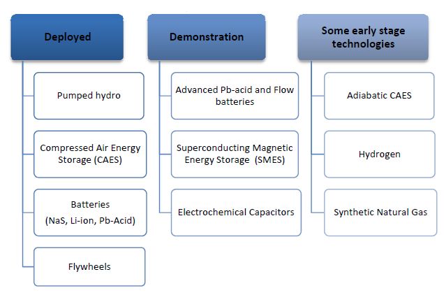
over time. Figure 2 lists technologies based on their present degree of adoption.” 9
Pumped hydro is one of the oldest and most mature energy storage technologies and represents
95% of the installed storage capacity. Other storage technologies, such as batteries, flywheels
and others, make up the remaining 5% of the installed storage base, are much earlier in their
deployment cycle and have likely not reached the full extent of their deployed capacity. Among
these deployed storage technologies, this DOE OE Strategic Plan for Energy Storage Safety will
focus primarily on batteries, with some attention to flywheels due to the rapid growth seen in
these two relatively new grid-scale technologies.
9
Grid Energy Storage Strategy. U.S. Department of Energy, Dec. 2013, p. 16.
12Figure 2. Maturity of Electricity Storage Technologies . 2.1 Pumped Hydro Storage Pumped hydro is so established as a deployed storage technology that this is not a focus technology for addressing safety concerns. With over 100 GW of installed capacity in the world, and the first hydroelectric plants opening in the 1800s, the technology is well understood without large uncertainty remaining concerning its safety and reliability. 2.2 Compressed Air Energy Storage (CAES) Although CAES is an earlier stage technology, the mechanics of conventional CAES have characteristics analogous to many commercial industrial processes, such as conventional piping and fittings. Established safety codes address the above-ground CAES pressure vessel concerns which are well mitigated with pressure relief valves implemented at pressures equal to 40% of the rupture pressure in steel vessels and 20% of the rupture pressure for fiber-wound vessels, as defined by code. Such established safety protocols in industry result in reduced concerns and uncertainly with respect to safety in CAES deployments. 13
2.3 Superconducting Magnetic Energy Storage (SMES)
SMES technology uses a superconducting coil to store DC current. As an early stage
technology, it has not proven itself to be a viable piece of the bulk storage market for deployed
technologies. As such, is not addressed in this strategy.

2.4 Flywheels
Though flywheels are relative newcomers to the grid energy storage arena, they have been used
as energy storage devices for centuries with the earliest known flywheel being from 3100 BC
Mesopotamia. Grid scale flywheels operate by spinning a rotor up to tens of thousands of RPM
storing energy in a combination of rotational kinetic energy and elastic energy from deformation
of the rotor. These systems typically have large rotational masses that in the case of a
catastrophic radial failure need a robust enclosure to contain the debris. However, if the mass of
the debris particles can be reduced through engineering design, the strength, size and cost of the
containment system can be significantly reduced. For example, laminated flywheels where the
bonding strength of the layers is lower that the tensile strength within a layer will “unwind”
rather than throw off large arc sections of the rotor material. The engineering designs and safety
factors in containing flywheels are not currently widely established by the CSRs and require
further research. Current safety validation testing involves burst testing to probe containment
integrity, loss-of-vacuum testing, overspeed testing of systems, as well as fatigue testing of
sample materials. 10

2.5 Capacitors
Electrochemical capacitors prompt similar concerns in terms of the safety of the stored energy
within an electrochemical device and failures of devices. They are not therefore addressed
independently here, but they do deserve attention in understanding and addressing safety for grid
storage. Validation techniques can be considered in the context of approaches taken for battery
safety.

10
  Flynn, M. M., Zierer J. J., Thompson, R. C. “Performance Testing of a Vehicle Flywheel Energy System” SAE Technical Paper
Series. 2005.
http://www.utexas.edu/research/cem/Energy_storage_photos/2005_Performance%20Testing%20of%20a%20Vehicular%20Flyw
heel%20Energy%20System%202005-01-0809.pdf

14
Electrostatic and electrolytic capacitors are used in board design and are a very common cause of
faults that can lead to cascading failure resulting in voltage and or current surges and overcharge
of storage devices or temperature rises that can lead to ignition of flammable materials either
within the capacitor or adjacent components.

2.6 Batteries
As electrochemical technologies, battery systems used in grid storage can be further categorized
as redox flow batteries, hybrid flow batteries, and secondary batteries without a flowing
electrolyte. For the purposes of this document, vanadium redox flow batteries and zinc bromine
flow batteries are considered for the first two categories, and lead-acid, lithium ion, sodium
nickel chloride and sodium sulfur technologies in the latter category. As will be discussed in
detail in this document, there are a number of safety concerns specific to batteries that should be
addressed, e.g. release of the stored energy during an incident, cascading failure of battery cells,
and fires.

3.0     State of Safety Validation in the U.S.

Several significant issues in the current state of safety validation that must be addressed,
including: passive safety plans, reactionary safety approaches, and ineffective first response
procedures. First, the typical safety plan is passive, i.e. addressing each deployed system on a
case-by-case basis rather than having global standards and protocols for safety. Historically,
technology has typically led regulations, i.e. each installation of megawatt-sized, battery-based
energy storage systems since the 1980s has marked a technological milestone in the development
and understanding of the operational characteristics of such large-scale battery systems. Because
each installation was unique in size, functionality, and design, the unifying safety validation
techniques and national CSR for the integrations and use of full systems was absent. While there
are substantial CSR in existence for individual components within a storage system, current
safety documents must now be updated to address the entire integrated system in order to fully
validate its operational safety. Overall system safety is still determined on an installation-by-
installation basis by the system vendor (either the system manufacturer or the system installer)
who is charged with satisfying owner requests and meeting any applicable CSR on behalf of the
owner. The CSR currently available and directives guide the approach to safety of systems on
the grid side of the meter. However, fire marshals typically have little oversight of activities on

15
the grid side of the meter, which is typically under the jurisdiction of the public utilities
commission. On the customer side, a similar approach is found, but is based on enforcement of
adopted CSR by state and local agencies. This individualized approach for evaluating safety is
the current modus operandi and ultimately hinders the time and cost of deploying systems.

Second, safety approaches are reactionary instead of proactive and predictive, thus unnecessarily
increasing costs with irrelevant and ineffective techniques. Energy storage systems
manufacturers, owners, and installers will use validation techniques for new systems based on
previous installation experience, disregarding differences in system type, battery chemistry, total
capacity, or deployment environment. The result of this approach is that the validation
techniques are not comprehensive, though substantial amounts of money and time are spent to
initiate them. An example of ineffective safety validation can be found in method used by the
Puerto Rico Electric Power Authority (PREPA) to install a 20 MW/17 MWh spinning
reserve/frequency regulation battery system in 1994. 11 This installation was patterned after a
similarly-sized, flooded-cell, lead-acid battery system installed at the West Berlin Electric Utility
Company (BEWAG) in Berlin in 1986. 12 Even though the PREPA installation was fashioned
after the BEWAG system, the local fire marshal in San Juan determined that the mandatory
safety requirements at the PREPA installation were significantly different. Differences in the
battery chemistry, the application space, and the deployment environment between the two
systems were not accounted for before PREPA was installed. This initial oversight resulted in
costly additional risk mitigation measures. PREPA was required to provide a structural design
on the second floor, which housed the battery, as a virtual swimming pool to hold all the water
required to extinguish a potential fire. In addition, PREPA was required to store on site a large
quantity of water for firefighting, along with its necessary pumping infrastructure. The
additional cost and space requirements, caused by the altered structural design of the building,
dramatically increased the deployment cost.

System owners are often required to establish a safety margin based on their best engineering
guess rather than on scientifically derived validation techniques developed from an

11
   Farber-DeAnda, Mindi. Boyes, John D. Wenceslao, Torres. “Lessons Learned from the Puerto Rico Battery Energy Storage
System.” Sandia National Laboratories, 1999.
12
   Wagner, Richard. “High-power lead-acid batteries for different applications.” Journal of Power Sources, Nov. 2004. p 496.

16
understanding of the active processes and limitations of the system, as was the case with the
PREPA system. As safety validation techniques are developed, validated, and documented for
each type of storage technology in every potential deployment environment, system owners will
be able to accurately estimate the full cost of each deployed system, including the risks
associated with insuring the installation. Significant decreases in uncertainty and gains in
process efficiencies will be the results of the development and documentation of these validation
techniques. Additionally, standard validation and deployment techniques can be used to improve
the safety and knowledge base of the first responders.

The third issue is that the historic and current first response procedures have also suffered as a
result of reactive, ineffective safety validation techniques and lack of standardized
documentation. Often, due to a lack of local experience in such events, response practices are
based on events that occurred in different technologies, but were reported nationally. In the late
1980s, the question of fire safety arose concerning the lead-acid inside the containerized battery
system PM250. The enclosed container design had to allow for the safe and fail-safe venting of
hydrogen emitted during charging. Consideration was also given to how a first responder could
look inside the container to observe the interior condition without opening the container’s large
doors. 13 However, neither design decision was addressed by the governing safety code, which
lacked specifications about the design of hydrogen venting or the size and location of the glass
portholes.

A reactive approach to energy storage safety is no longer viable. The number and types of
energy storage deployments have reached a tipping point with dramatic growth anticipated in the
next few years fueled in large part by major, new, policy-related storage initiatives in
California 14, Hawaii 15, and New York. 16 The new storage technologies likely to be deployed in

13
   Corey, Garth; Nerburn, William; Porter, David. “Final Report on the Development of a 250-kW Modular, Factory-Assembled
Battery Energy Storage System.” Sandia National Laboratories, 1998.
14
   Program Opportunity Notice: “Developing Advanced Energy Storage Technology Solutions to Lower Costs and Achieve
Policy Goals,” PON-13-302. http://www.energy.ca.gov/contracts/PON-13-302/00_PON-13-302_Energy_Storage_2014-07-
31.pdf
15
   Hawaiian Electric. O’ahu Energy Storage System, Request for Proposals No. 072114-01.
http://www.hawaiianelectric.com/vcmcontent/StaticFiles/pdf/ESS_RFP_No_072114-01.pdf
16
   Reforming the Energy Vision: NYS Department of Public Service Staff Report and Proposal. Case 14-M-0101. 2014.
http://www3.dps.ny.gov/W/PSCWeb.nsf/96f0fec0b45a3c6485257688006a701a/26be8a93967e604785257cc40066b91a/$FILE/A
TTK0J3L.pdf/Reforming%20The%20Energy%20Vision%20%28REV%29%20REPORT%204.25.%2014.pdf

17
response to these and other initiatives are maturing too rapidly to justify moving ahead without a
unified scientifically based set of safety validation techniques and protocols. A compounding
challenge is that startup companies with limited resources and experience in deployment are
developing many of these new storage technologies. Standardization of the safety processes will
greatly enhance the cost and viability of new technologies, and of the startup companies
themselves. The modular nature of ESS is such that there is just no single entity clearly
responsible for ESS safety; instead, the each participant in the energy storage community has a
role and a responsibility. The following sections outline the gaps in addressing the need for
validated grid energy storage system safety.

4.0        Key Aspects for Addressing Energy Storage Safety

Safety of any new technology can be broadly viewed as having three intimately linked aspects,
as follows: 1) the system must be engineered and validated to the highest level of safety; 2)
techniques and processes must be developed to respond to incidents when they occur; and 3) best
practices and system requirements must then be reflected in CSR so that there is uniform,
consistent, understandable and enforceable criteria that must be satisfied when designing,
building, testing, and deploying the system. It is clear within the grid energy storage community
that specific efforts must be started or expanded to address each of these three areas. 17
Specifically, as the materials, technologies, and deployment applications for storing energy are
created, new techniques and protocols must be developed to validate their safety and ensure the
risk of failure and loss is minimized. These new techniques and protocols will allow
manufacturers to design the systems to be as safe as possible, especially for the first and second
responders. These techniques will additionally be used to educate first responders on the
associated risk of responding to an incident involving the new technologies. Finally, codes,
standards, and regulations will be developed to efficiently memorialize these design rules,
response procedures and safety performance metrics to all stakeholders.

17
     DOE OE Energy Storage Safety Workshop, Albuquerque, NM. 2014.

18
5.0 Validation Techniques To date, the most extensive energy storage safety and abuse R&D efforts have been done for Electric Vehicle (EV) battery technologies. These efforts have been limited to lithium ion, lead- acid and nickel metal hydride chemistries and, with the exception of grid-scale lead-acid systems, are restricted to smaller size battery packs applicable to vehicles. 18 Lessons learned from EV safety R&D can be useful in developing the grid storage energy storage safety area, and in fact, the use of EV batteries that are beyond their automotive service life in grid storage is emerging as a viable second life. However, the increased scale, complexity, and diversity in technologies being proposed for grid- scale storage necessitates a comprehensive strategy for adequately addressing safety in grid storage systems. The technologies deployed onto the grid fall into the categories of electro-chemical, electromechanical, and thermal, and are themselves within different categories of systems, including CAES, flywheels, pumped hydro and SMES. This presents a significant area of effort to be coordinated and tackled in the coming years, as a number of gap areas currently exist in codes and standards around safety in the field. R&D efforts must be coordinated to begin to address the challenges. 5.1 Current Validation Techniques An energy storage system can be categorized primarily by its power, energy and technology platform. For grid-scale systems, the power/energy spectrum spans from smaller kW/kWh to large MW/MWh systems. Smaller kW/kWh systems can be deployed for residential and community storage applications, while larger MW/MWh systems are envisioned for electric utility transmission and distribution networks to provide grid level services. This is in contrast to electric vehicles, for which the U.S. Advanced Battery Consortium (USABC) goals are both clearly defined and narrow in scope with an energy goal of 40 kWh. While in practice some EV packs are as large as 90 kWh, the range of energy is still small compared with the grid storage applications. This research is critical to the ability of first responders to understand the risks posed by ESS technologies and allow for the development of safe stratagies to minimize risk and mitigate the event. 18 Doughty, Daniel H.; Pesaran, Ahmad A. “Vehicle Battery Safety Roadmap Guidance.” National Renewable Energy Laboratory. Oct. 2012. http://www.nrel.gov/docs/fy13osti/54404.pdf 19
Table 1. Range of Storage Technology and Size

                                                                            Storage Size          Storage Size
Storage space             Technologies             Application
                                                                            (energy)              (power)
Electric Vehicle          Batteries (Li-ion,       City and
                                                                            40 – 90 kWh           80 kW 19
Technology                NiMH, Pb-acid)           highway driving
                          Batteries, CAES,
Stationary                flywheels,               Over 17 use              5 kWh – 1
                                                                                                  10 kW – 1 GW
Storage                   pumped hydro             cases identified 20      GWh 21
                          and SMES

Furthermore, the diversity of battery technologies and stationary storage systems is not generally
present in the EV community. Therefore, the testing protocols and procedures used historically
and currently for storage systems for transportation are insufficient to adequately address this
wide range of storage systems technologies for stationary applications. Table 1 summarizes the
high level contrast between this range of technologies and sizes of storage in the more
established area of EV. The magnitude of effort that must be taken on to encompass the needs of
safety in stationary storage is considerable because most research and development to improve
safety and efforts to develop safety validation techniques are in the EV space.

Notably, the size of EV batteries ranges by a factor of two; by contrast, stationary storage scales
across many orders of magnitude. Likewise, the range of technologies and uses in stationary
storage are much more varied than in EV. Therefore, while the EV safety efforts pave the way in
developing R&D programs around safety and developing codes and standards, they are highly
insufficient to address many of the significant challenges in approaching safe development,
installation, commissioning, use and maintenance of stationary storage systems.

19
     Mackenzie, Angus. “2013 Motor Trend Car of the Year: Tesla Model S. Motor Trend. 2013.
20
  Akhil, Abbas; et al. “DOE/EPRI 2013 Electricity Storage Handbook in Collaboration with NRECA.” Sandia National
Laboratories. July 2013.
21
     The Tesla Motors Team. “A Supercharging Milestone.” Tesla Motors. July 2014.

20
An additional complexity of grid storage systems is that the storage system can either be built
on-site or pre-assembled, typically in shipping containers. These pre-assembled systems allow
for factory testing of the fully integrated system, but are exposed to potential damage during
shipping. For the systems built on site, the assembly is done in the field; much of the safety
testing and qualification could potentially be done by local inspectors, who may or may not be as
aware of the specifics of the storage system. Therefore, the safety validation of each type of
system must be approached differently and each specific challenge must be addressed.
5.2 Areas of Interest in Safety Validation
Given the maturity and documented use of pumped hydro and CAES, batteries and flywheels are
currently the primary focus for enhanced grid-scale safety. For these systems, the associated
failure modes at grid-scale power and energy requirements have not been well characterized and
there is much larger uncertainty around the risks and consequences of failures. This uncertainty
around system safety can lead to barriers to adoption and market success, such as difficulty with
assessing value and risk to these assets, and determining the possible consequences to health and
the environment. To address these barriers, concerted efforts are needed in the following areas:
• Materials Science R&D – Research into all device components
• Engineering controls and system design
• Modeling
• System testing and analysis
• Commissioning and field system safety research
It is a notable challenge within the areas outlined above to develop understanding and confidence
in relating results at one scale to expected outcomes at another scale, or predicting the interplay
between components, as well as protecting against unexpected outcomes when one or more
failure mode is present at the same time in a system. Extensive research, modeling and
validation are required to address these challenges. Furthermore, it is necessary to pool the
analysis approaches of failure mode and effects analysis (FMEA) and to use a safety basis in
both research and commissioning to build a robust safety program. Furthermore, identifying,
responding and mitigating to any observed safety events are critical in validating the safety of
storage.
21A holistic view with regard to setting standards to ensure thorough safety validation techniques is the desired end goal; the first step is to study on the R&D level failure from the cell to system level, and from the electrochemistry and kinetics of the materials to module scale behavior. Detailed hazards analysis must be conducted for entire systems in order to identify failure points caused by abuse conditions and the potential for cascading events, which may result in large scale damage and/or fire. While treating the storage system as a “black box” is helpful in setting practical standards for installation, understanding the system at the basic materials and chemistry levels and how issues can initiate failure at the cell and system level is critical to ensure overall system safety. In batteries, understanding the fundamental electrochemistry and materials changes under selected operating conditions helps guide the cell level safety. Knowledge of cell-level failure modes and how they propagate to battery packs guides the cell chemistry, cell design and integration. Each system has different levels of risk associated with basic electrochemistry that must be understood; the tradeoff between electrochemical performance and safety must be managed. There are some commonalities of safety issues between storage technologies. For example, breeching of a Na/S (NAS) or Na/NiCl2 (Zebra) battery could result in exposure of molten material and heat transfer to adjacent cells. 22,23,24 Evolution of H2 from lead-acid cells or H2 and solvent vapor from lithium-ion batteries during overcharge abuse could results in a flammable/combustible gas mixture. 25,26,27,28 Thermal runaway in lithium-ion (Li-ion) cells could transfer heat to adjacent cells and propagate the failure through a battery. 29 Moreover, 22 “Cause of NAS Battery Fire Incident” NGK Insulators, LTD. June, 2012. 23 A. V. Van Zyl; C.-H Dustmann (Nov. 1995). “Safety Aspects of Zebra High Energy Batteries,” in Conference Proceedings, WEVA Conference for Electric Vehicle Research, Development and Operation, November 13, 14, 15, 1995; Paris. Bruxelles, Belgium. pp. 57–63. 24 Current Status of Health and Safety Issues of Sodium/Metal Chloride (Zebra) Batteries” NREL/TP-460-25553. November, 1998. 25 A. J. Salkind, A. G. Cannone, F. A. Trumbure in “The Handbook of Batteries” D. Linden and T. B. Reddy, 3rd Edition, 2002, pp. 23.77-23.78. 26 A. W. Metwally “Generic environmental and safety assessment of five battery energy storage systems”, Electr. Power Res. Inst. 1982 27 D. P. Abraham, E. P. Roth, R. Kostecki, K. McCarthy, S. MacLaren, D. H. Doughty, “Diagnostic examination of thermally abused high-power lithium-ion cells” J. Power Sources, 161. 2006, pp. 648-657 28 G. Nagasubramanian and C. J. Orendorff, “Hydrofluoroether electrotes for lithium-ion batteries: Reduces gas decomposition and nonflammable” J. Power Sources, 196. 2011, pp. 8604-8609. 29 Mikolajczak, Celina; Kahn, Michael; White, Kevin; Long, Richard Thomas. “Lithium-Ion Batteries Hazard and Use Assessment.” Exponent Failure Analysis Associates, Inc. July 2011. 22
while physical hazards are often considered, health and environmental safety issues also need to
be evaluated to have a complete understanding of the potential hazards associated with a battery
failure. These may include the toxicity of gas species evolved from a cell during abuse or when
exposed to abnormal environments, 30,31 toxicity of electrolyte during a cell breech or spill in a
Vanadium redox flow battery (VRB), 32 environmental impact of water runoff used to extinguish
a battery fire containing heavy metals. 33 Flywheels provide an entirely different set of
considerations, including mechanical containment testing and modeling, vacuum loss testing,
and material fatigue testing under stress. A holistic approach needs to be taken to address all of
the cell or component level through system-level safety issues with adequate mitigations,
diagnostics, monitoring, and engineered controls.

Failure mode and effects analysis (FMEA) is conducted in installations. Research must consider
current FMEA tactics specific to stationary storage, identify weaknesses in their execution with
special attention to systems that have encountered field failure caused by abuse, and failures that
were not well controlled, leading to cascading events resulting in large scale damage and/or fire.
A comprehensive look at system level concerns with regard to failures and safety can be
approached when R&D is incorporated into the standard basis for safety.

5.3 Materials Science R&D
The topic of Li-ion battery safety is rapidly gaining attention as the number of battery incidents
increases. Recent incidents, such as a cell phone runaway during a regional flight in Australia
and a United Parcel Service plane crash near Dubai, reinforce the potential consequence of Li-
ion battery runaway events. The sheer size of grid storage needs and the operational demands
make it increasingly difficult to find materials with the necessary properties, especially the
required thermal behavior to ensure fail-proof operation. The main failure modes for these
battery systems are either latent (manufacturing defects, operational heating, etc.) or abusive
(mechanical, electrical, or thermal).

30
   A. J. Salkind, A. G. Cannone, F. A. Trumbure in “The Handbook of Batteries” D. Linden and T. B. Reddy, 3rd Edition, 2002,
pp. 23.77-23.78.
31
   D. P. Abraham, E. P. Roth, R. Kostecki, K. McCarthy, S. MacLaren, D. H. Doughty, “Diagnostic examination of thermally
abused high-power lithium-ion cells” J. Power Sources, 161. 2006, pp. 648-657.
32
   “Toxicology Profile for Vanadium” U.S. Department of Health and Human Services, Public Health Service, Agency for
Toxic Substances and Disease Registry. September 2012.
33
   Wesoff, Eric. “Battery Room Fire at Kahuku Wind-Energy Storage Farm.” Green Tech Grid. August 2012.

23
Any of these failures can increase the internal temperature of the cell, leading to electrolyte
decomposition, venting, and possible ignition. While significant strides are being made, major
challenges remain in combating solvent flammability still remain, which is the most significant
area that needs improvement to address safety of Li-ion cells, and is therefore discussed here in
greater detail. To mitigate thermal instability of the electrolyte, a number of different approaches
have been developed with varied outcomes and moderate success. Conventional electrolytes
typically vent flammable gas when overheated due to overcharging, internal shorting,
manufacturing defects, physical damage, or other failure mechanisms. The prospects of
employing Li-ion cells in applications depend on substantially reducing the flammability, which
requires materials developments (including new lithium salts) to improve the thermal properties.
One approach is to use fire retardants (FR) in the electrolyte as an additive to improve thermal
stability. Most of these additives have a history of use as FR in the plastics industry. Broadly,
these additives can be grouped into two categories—those containing phosphorous and that
containing fluorine. A concerted effort to provide a hazard assessment and classification of the
event and mitigation when an ESS fails, either through internal or external mechanical, thermal,
or electrical stimulus is needed by the community.

Significant efforts have been made to develop tests to determine the safety margin in Li-ion
batteries in both mobile devices and vehicles. For example, significant efforts have been made
in the qualification of the response to battery cell thermal runaway, 34,35,36,37 safety response in
packs to mechanically induced failure, 38 and model thermal abuse of cells. 39 A comprehensive
report prepared by Exponent Failure Analysis Associate, Inc. for the Fire Protection Research
Foundation provides a detailed review of validation techniques as part of the Lithium-Ion
Batteries Hazard and Use Assessment. 40 This review and its references describe the state of

34
   J.R. Dahn, E.W. Fuller, M. Obrovac, U. Vonsacken. “Solid State Ionics.” 69. 1994, 265.
35
   D. Belov, M.H. Yang, “Solid State Ionics.” 179. 2008, 1816.
36
   D. Belov, M.H. Yang, J. “Solid State Electr.” 12, 2008, 885.
37
   S.J. Harris, A. Timmons, W.J. Pitz. “J Power Sources.” 193, 2009, 855.
38
   R.M. Spotnitz, J. Weaver, G. Yeduvaka, D.H. Doughty, E.P. Roth. “J Power Sources.” 163, 2007, 1080.
39
   G.H. Kim, A. Pesaran, R. Spotnitz. “J Power Sources” 170, 2007, 476.

24
understanding around battery failures and research into improved safety at that time, but are
limited in the material systems and the size of the systems reviewed.

5.4 Electrolyte Safety R&D
The combustion process is a complex chemical reaction by which fuel and an oxidizer in the
presence of heat react and burn. Convergence of heat (an oxidizer) and fuel (the substance that
burns) must happen to have combustion. The oxidizer is the substance that produces the oxygen
so that the fuel can be burned, and heat is the energy that drives the combustion process. In the
combustion process a sequence of chemical reactions occur leading to fire. 41 In this situation a
variety of oxidizing, hydrogen and fuel radicals are produced that keep the fire going until at
least one of the three constituents is exhausted.

5.4.1 Electrolytes
Despite several studies on the issue of flammability, complete elimination of fire in Li-ion cells
has yet to be achieved. One possible reason for the failure could be linked to lower flash point
(FP) (
•    High voltage stability
       •    Comparable conductivity to traditional electrolytes
       •    Lower flame propagation rate or no fire at all
       •    Lower self-heating rate
       •    Stable against both the electrodes
       •    Able to wet the electrodes and separator materials
       •    Higher onset temperature for exothermic peaks with reduced overall heat production
       •    No miscibility problems with co-solvents

Electrolyte non-flammability is essential for cell safety. Enhanced safety of electrolytes
containing FR additives is mostly accompanied by performance degradation including low
capacity utilization, high rate of capacity fade, or poor low temperature performance.
Additionally, some are electrochemically unstable and are consumed during cycling, becoming
unavailable for cell protection with time. Furthermore, limited information is available in the
open literature on the performance of additives in large capacity cells under actual use conditions
and subsequent abuse conditions. The higher energy density of Li-ion cells can only result in a
more volatile device, and while significant efforts have been put forth to address safety,
significant research is still needed. To improve safety of Li-ion batteries, the electrolyte
flammability needs significant advances or further mitigation is needed in areas that will contain
the effects of failures to provide graceful failures with safer outcomes in operation.

5.4.2 Additives
The most commonly accepted mechanism for fire propagation relies on a radical generation
mechanism. Ground state oxygen absorbs heat and produces energetic and extremely reactive
singlet oxygen. The identified mechanism clearly indicates that hydrogen radical and singlet
oxygen play a key role in sustaining the flame. 44 This is the target for many of the materials
proposed as FR additives. If a FR material is able to sufficiently bind to the free radicals during
the reaction cascade, then propagation of the flame will be suppressed.

44
     J.L. Jurs. “Development and Testing of Flame Retardant Additives and Polymers.” Rice University. 2007, 303.

26
You can also read