Evolution of a Cognitive Architecture for Social Robots: Integrating Behaviors and Symbolic Knowledge - MDPI
←
→
Page content transcription
If your browser does not render page correctly, please read the page content below
applied
           sciences
Article
Evolution of a Cognitive Architecture for
Social Robots: Integrating Behaviors and
Symbolic Knowledge
Francisco Martín 1,∗ , Francisco J. Rodríguez Lera 2 , Jonatan Ginés 3              and Vicente Matellán 4
 1    Intelligent Robotics Lab, Rey Juan Carlos University, 28943 Móstoles, Spain
 2    Escuela de Ingenierías Industrial e Informática, University of León, 24007 León, Spain; fjrodl@unileon.es
 3    Escuela Internacional de Doctorado, Rey Juan Carlos University, 28933 Móstoles, Spain;
      jonatan.gines@urjc.es
 4    Supercomputación Castilla y León, SCAYLE, 24007 León, Spain; vicente.matellan@unileon.es
 *    Correspondence: francisco.rico@urjc.es

 Received: 31 July 2020; Accepted: 26 August 2020; Published: 1 September 2020

 Abstract: This paper presents the evolution of a robotic architecture intended for controlling
 autonomous social robots. The first instance of this architecture was originally designed according
 to behavior-based principles. The building blocks of this architecture were behaviors designed
 as a finite state machine and organized in an ethological inspired way. However, the need of
 managing explicit symbolic knowledge in human–robot interaction required the integration of
 planning capabilities into the architecture and a symbolic representation of the environment and
 the internal state of the robot. A major contribution of this paper is the description of the working
 memory that integrates these two approaches. This working memory has been implemented as
 a distributed graph. Another contribution is the use of behavior trees instead of state machine
 for implementing the behavior-based part of the architecture. This late version of the architecture
 has been tested in robotic competitions (RoboCup or European Robotics League, among others),
 whose performance is also discussed in this paper.

 Keywords: robotic architectures; reactivity; planning; knowledge representation

1. Introduction
      Organizing the capabilities of autonomous systems is an old, recurrent, and still open problem in
artificial intelligence based systems, and in service robotics in particular, where this paper is focused.
These different ways of organization are usually known as the architecture of the robot. Both software
and cognitive architectures form the backbone of complete robotic systems [1].
      From a historical perspective, Shakey (https://www.sri.com/case-studies/the-man-the-myth-
the-legend-meet-shakey-the-robot-the-worlds-first-ai-based-robot/) is considered as the first service
robot to embody an artificial intelligence system. Its cognitive architecture was based on symbolic
principles. It used the Stanford Research Institute Problem Solver (STRIPS) planner [2] as the center of
their control system.
      The Shakey project generated a lot of remarkable results, including the development of the A*
search algorithm; the Hough transform, or the visibility graph method for calculating 2-D trajectories
to a predefined goal. Shakey’s top-down approach was criticized for not being able to deal wit real
world through perception and action in real-time. According to Rodney Brooks [3], the problem was
that Shakey’s cognitive architecture was based on the idea of decomposing the intelligent system into
information processing units which had to interact with each other via a symbolic representation.

Appl. Sci. 2020, 10, 6067; doi:10.3390/app10176067                                 www.mdpi.com/journal/applsci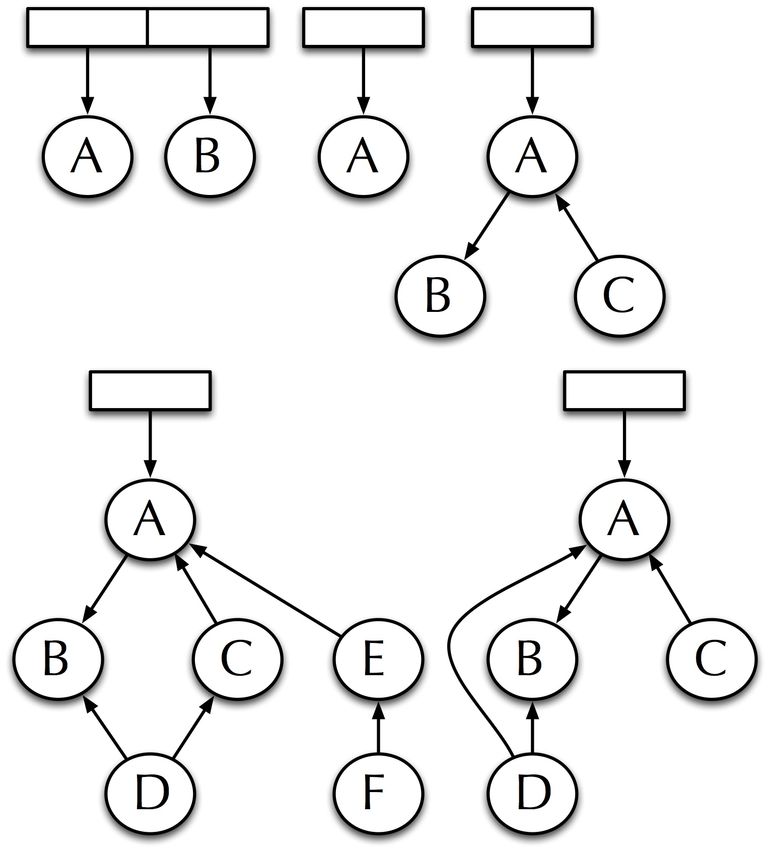
Appl. Sci. 2020, 10, 6067                                                                        2 of 16

      This approach led to the emergence of behavior-based robotics during the 80 s and 90 s,
that basically proposes that artificial intelligent systems should be decomposed into independent
and parallel activity producers which interface directly to the world through perception and action,
rather than interface to each other [4].
      Using combinations of behaviors rather than reasoning over world models seem to be robust,
modular, and adequate for real-time robot control, but the ability to reason about world models,
map making, or long-term planning were still required for many tasks, notably in human–robot
interaction tasks. In addition, behavior-based architectures introduced the new problem of how to
compose behavior interactions. This lead to introduce the concept of hybrid architectures, which means
how to introduce high-level capabilities without losing low-level advantages.
      Hybrid architectures usually consist of three layers: a set of reactive control mechanisms,
a monitoring execution mechanism, and an upper layer for time-consuming deliberative
computations [5]. A well known example of hybrid architecture is Autonomous Robot Architecture
(AuRA) [6]. The goal of this architecture is how to introduce high-level capabilities without losing
low-level advantages. Once reactive execution begins, deliberation is deactivated, unless it detects a
failure. Failure recovery works up the hierarchy, that is, it revises the plan sequence based on input
available so far.
      The previous taxonomy of robot control architectures refers to the ”cognitive” dimension, each of
them having different origins. Therefore, behavior-based architectures have a biological inspiration,
symbolic approaches are more related to psychology, and hybrid ones could be considered engineer
inspired. A complete analysis of different and more detailed ways of classifying architectures can be
found in [7].
      Another dimension analysis robotic architecture has to do with their software implementation.
Originally, each architecture was developed for a specific robot. However, the need for re-configuring
and re-using robot’s behaviors has lead to the emergence of frameworks for implementing this
architectures. These frameworks provide component reusability, modularity, component composition,
life-cycle management, dynamic reconfiguration, etc. One of the first widely distributed frameworks
was MisionLab [8], but many other systems appeared in different robotic hubs, as CARMEN [9]
in Carnegie Mellon, or developed by manufacturers as ARIA (Mobile Robotics), or sponsored by
international organizations as Orocos [10] by the European Union. A systematic review of the software
development frameworks for robots can be analyzed in [11].
      Nowadays, Robotic Operating System (ROS) [12] is considered the de facto standard as software
architecture in the research community. However, there is no similar standard on the cognitive field.
Hybrid architectures are nowadays the dominant paradigm, but there is not a consensus in the robotics
research community about which is the right approach, or even if there should be a correct one.
      This paper presents the evolution of the cognitive and software architecture jointly developed
by the robotics research group at the Universities of León and Rey Juan Carlos. The need of a
specific architecture emerged when the collaboration between the two groups that make up the
Gentlebots robotic team (https://gsyc.urjc.es/~dvargas/gentlebots) required modular decomposition
and frequent reconfigurations to adapt to different competitions that the team was entering. Software
reusability has let the authors reuse the code in different robots—four legged ones as the Aibo robotic
robot in RoboCup Soccer competitions, bipedal as Nao, and wheeled ones as TIAGo or RB1 in the
European Robotics League. Figure 1 summarizes the timeline evolution of the architecture.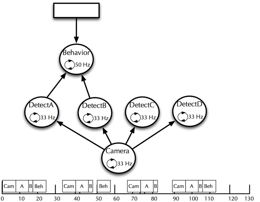
Appl. Sci. 2020, 10, 6067                                                                            3 of 16

                            Figure 1. Historical evolution of the Gentlebots robot architecture.

1.1. Evolution of the Proposed Architecture
      Authors consider that BICA, Behavior-based Iterative Component Architecture, [13] was the first
official name of this still evolving architecture. BICA shows the outcome of previous efforts to build an
ethological inspired architecture based on schemas names JDE [14]. It has evolved both in the cognitive
aspect, incorporating symbolic planning to the original behavior based approach, but also in the
software aspect, evolving from a proprietary framework to be implemented on ROS middleware [15].
BICA evolution also reflects the lessons learned obtained from the competitions where it has been
evaluated [16], mainly from RoboCup and the RoCKIn competitions.
      The originally behavior-based BICA was enlarged in 2013 [17] to include motivational principles
for enhancing the social robot acceptability [18]. As a result, the conceptual cognitive architecture based
on BICA that was called HIMoP [19] was introduced. After that, part of the conceptual principles,
mainly the planning part, were included into BICA, which led to the the use of a symbolic planner to
define the tasks in robotics competitions [20]
      This paper reviews this timeline, showing the two main cognitive elements leading the
architecture development till the date: (1) A component-based architecture for behavior generation;
(2) a planning-based architecture for long-term behavior generation.
      The main contributions of the work described in this article are first the working memory
system added to BICA that let the robot manage different types of knowledge on real time.
Secondly, the integration of behavior trees to enhance the generation of new behaviors in the robot,
that previously were made using finite state machines (FSMs)
      Working memory represents the knowledge, and lets to be read and manipulated to plan
the robot’s actions. Blackboard-based systems have been used in robotics since the 1990s [21].
They provide a key/value information-sharing mechanism. The use of graphs is a further step in the
representation of knowledge. This representation, based on vertices and arcs, provides a more flexible
way of storing relationships among the elements stored in the graph than facts on a whiteboard [22].
Our proposal provides a memory that combines modularity and functionality, in addition to using a
distributed approach. Different modules use memory not only to store information but also to trigger
the robot’s actuation. This information is visible to all working memory users but is only relevant to
those users who use it. A systematic review of knowledge representation for service robots can be
analyzed in [23].
      Behavior trees emerged and were created to model the behavior of non-player characters (NPCs)
in video games, and are currently being used [24,25] to model tasks in robot behaviors, due to their
expressive capacity being superior to FSMs. In our proposal, we combine behavior trees and planning.
Unlike [26], we separate the planning layer from the task layer, in which we use behavior trees.
      The rest of the paper is organized as follows. Section 2 describes the first instance of the
architecture based on reactive components. Section 3 starts from the limitations of this approach
to deal with high-level tasks, in particular when interacting with humans and managing symbolic
representations, that led us to the addition of a symbolic planner. This integration led to major
contribution of the paper—the working memory described in Section 4. In addition to the evolution in
the cognitive aspect, BICA has also evolved in its software implementations, in particular, Section 5
details the second major contribution described—the addition of behavior trees for defining behavioral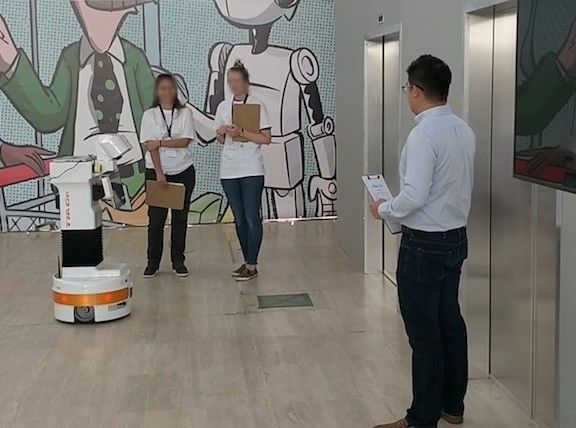
Appl. Sci. 2020, 10, 6067 4 of 16
components. Section 6 focuses on the implementation and testing issues and the final section
summarizes the contributions.
2. Component-Based Architecture
The origins of the BICA architecture can be traced back to a behavior-based project originally
conceived for easy design behaviors for the Aibo robotic dog used in the RoboCup Soccer competition.
In this early version, named MBA [27], behaviors were the basic blocks of the architecture.
Each behavior had a goal that must be satisfied, and may have one or more prerequisites. If any
behavior’s prerequisite was not met, it was set as a goal to the lower level.
The public version of that preliminary architecture was named Behavior-based Iterative
Component Architecture (BICA) (https://github.com/IntelligentRoboticsLabs/BICA) [13].
The minimum unit of execution was defined as the component, and the behavior of the robot emerged
from the concurrent execution of various components.
Components (Figure 2) are software processes that, when active, are executed at a certain
frequency depending on their function. Each component can establish other components that it
requires for its operation, as shown in the left part of Figure 3, which we call dependencies. When a
component is active, it cascades its dependencies, collecting the result of its computation or establishing
the input it requires for its operation.
Figure 2. A Behavior-based Iterative Component Architecture (BICA) component.
Using this approach, we can create activation trees that correspond to the skills of the robot
(navigation, perception, HRI, manipulation), whose leaves are the sensors and actuators, as shown
in right part of Figure 3. Behaviors would be created by incorporating these trees with the skills as
subtrees of a larger tree.
Figure 3. Different possible topologies in BICA (left). An example of a perceptive behavior
implementation using BICA (right).
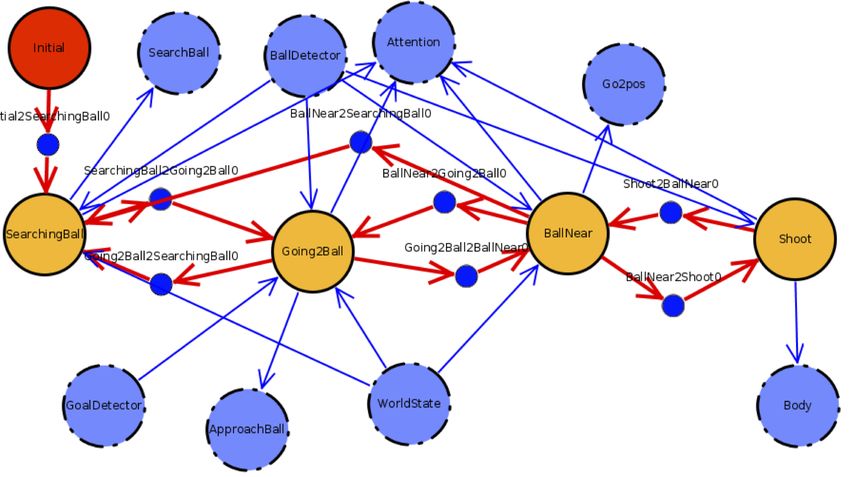
We have implemented a particular type of component that contains a finite state machine and
can be found multiple times anywhere in the tree. Dependencies are established at the state level,
allowing a certain degree of intelligence about which dependencies are activated at any given time.
We consider this approach to be a two-layer architecture: the bottom layer contains the robot’s
skills (navigation, perception, performance), and the top layer contains FSMs that control the robot’s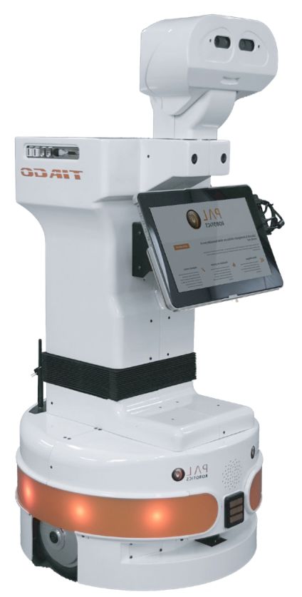
Appl. Sci. 2020, 10, 6067                                                                           5 of 16

mission and decide when to activate which skills. A component that requires information from another
component obtains it with direct connections, for the moment lacking a transparent model of working
memory or something similar.
     Several aspects must be taken into account:

•    Components can be activated from more than one component.
•    A component becomes inactive when no component requires its activation. The only exception is
     the root of the activation tree.
•    The system must be robust to components that suddenly disappear. All its dependencies must be
     able to discover this fact to be deactivated if it is its only activator.
•    The system must be able to handle components that start late. If a component is among the
     dependencies of an active component, it must be activated immediately.

     This architecture is appropriate for many applications. We have played robot soccer and
participated in social robot competitions with this approach. The disadvantages that we identified were:

•    The direct connection between activator-dependency components limits that several components
     cooperate at the same level.
•    State machines do not scale well when applications become more complex, and the number of
     eventualities that can occur begins to grow.

3. Planning-Based Architecture
     As presented in the previous section, components can contain finite state machines within,
allowing a qualitative leap in generating behaviors. FSMs let us overcome the limitation of
implementing only reactive behaviors, being able to implement more complex behaviors. FSMs
let us organize the mission of a robot into phases, activating different skills in each one. Furthermore,
a skill can adapt its performance by dividing it into different states. By having multiple FSMs at
different levels, we can easily implement hierarchical finite state machines (HFSMs). This approach is
appropriate for a large number of applications.
     HFSMs have also their limitations. Behavior designers need to know all the steps a robot must
take to accomplish its mission. Not only that, designers must also anticipate all the error situations
that can occur in each of the states. Separate states handle each contingency, and transitions to these
states need to cover all the error conditions. Additionally, there should be a transition to the pre-error
state, once managed the contingency. If an error can occur in more than one state, it is possible to
duplicate the state that handles the exception, or use a more complex technique, since it is necessary to
differentiate which state to return to after the contingency.
     Due to these limitations, we decided to include symbolic planning abilities in our architecture
instead of defining states and transitions, planning specifies actions and under which conditions they
can be applied. Given a goal, a planner calculates a plan (a sequence of actions) to obtain it. A planning
system checks at run-time whether the conditions of the current action continue to be met. If any
condition is not met, the planner generates an alternative plan. If the condition verifies that a problem
has not occurred (that the robot has a battery, for example), the alternative plan will include actions to
solve it (charge its battery), followed by actions until the objective is met.
     Planning Domain Definition Language (PDDL) [28] is an attempt to standardize languages for
defining actions, conditions, and goals for different planners. It was fundamentally inspired by STRIPS
and is the basis for many symbolic planners. Two components are required to generate a plan using
PDDL: a domain and a problem. The domain specifies:

•    The types of instances that can exist.
•    The types of predicates available. These predicates are facts, which can contain several instances
     to which it refers.
Appl. Sci. 2020, 10, 6067                                                                                                                   6 of 16

•    Actions, with their preconditions and their effects, expressed in terms of predicates and
     logical operators.

     A problem is a set of instances and predicates. It is the starting point from which we want to
create a plan. A plan also contains the goal to be achieved. We could consider a domain as the static
part and the problem the active part.
     A planner is the core of a planning system but also contains other parts, as shown in Figure 4:
A planning system also contains a knowledge base where to store the problem and provides all the
mechanisms to query/update its content. The planning system reads the plan generated by the planner
and executes the actions in the plan. Therefore, it must be a standard interface to activate actions and
pass them the arguments that that plan contains. The planning system is also responsible for checking
the conditions of the action at run-time, as the knowledge base could be updated with new information
beyond the effect of the successfully performed actions.
     Our architecture grew with the incorporation of a planning system, creating three new layers,
as shown in Figure 5.

                                                                                                                   Actions controllers

          PDDL                                                                                                         External comms
          Domain
                                                                          Action A
          File                                                                                                          Action deliveries
                      Knowledge Base

                            PDDL
                            Model                                         Action B
                                          Planner / Executor

                         Scene
                         Database
                                                                          Action N

                                          Figure 4. The components of a planner system.

                                                               Robot HW
                                                                 Tier 5

                                                                Skills
                                                                Tier 4

                                                                Actions
                                                                 Tier 3

                                                               Planning
                                                                Tier 2

                                                               Symbolic
                                                                Tier 1

                                                                                FSM state transition
                                    Component
                                                                                Layer invocation
                                    Action implementation
                                                                                Action execution sequence (plan)

                                       FSM State                                Component Activation

                                                                                Access to sensor/actuators

                                        Figure 5. Layered planning-centered architecture.
Appl. Sci. 2020, 10, 6067 7 of 16
• The inner level, or tier 1, works at a symbolic level based on the information contained in the
planning system knowledge base. This layer controls the robot’s mission, establishing the goal to
be achieved in each phase. We implemented it with a component that included FSM, which allows
us also to use HFSM if necessary.
• The planning layer contained the planning system.
• The action layer was the border between the symbolic and the sub-symbolic level. The actions
are idle waiting to be activated and the arguments for their activation. The actions implement the
concrete control actions to act.
We have implemented the actions as components, so that they can declare at design time what
skills they require, being the root of an activation tree like those that already existed previously in
our architecture. Actions could even be implemented as FSM if necessary. These trees are focused
on control instead of resolving a complete problem. Skills are at the bottom layer, which was what
previously existed to include a planning system.
The knowledge base is the first working memory that we introduce in architecture by being able
to share information between layers. Actions introduce predicates into the working memory, which are
used at the top layer to make decisions. Unfortunately, the knowledge base can only contain symbolic
information. For this reason, from the action layer downward, direct connections to the components
that produce the information continue to be predominate.
We develop several modules that can take part in a concrete application. Each module contains
a specification of what actions it implements and what types and predicates it provides. During the
system startup of our architecture, the pieces of domains provided by each module compose a single
domain, specific to the application that is running.
Including all the improvements previously exposed has meant a qualitative leap in our cognitive
architecture:
• Our architecture is capable of solving more complex problems.
• There is a symbolic level in which it is easier to reason at a high level.
• It includes a working memory accessible from various levels.
4. The Working Memory
The first consequence of including a planning system in BICA was the need of increasing the
number of layers to accommodate the planning layer and the action layer, so the distance between
skills and mission control increases. Furthermore, the ability to address more complex applications
requires clarifying and standardizing information flows within a layer and between layers. It is easy to
get lost among the explicit connections established in each application.
At this point, we address the creation of working memory. Traditionally, robot software architects
have used whiteboard-based working memories since the earliest implementations of cognitive
architectures. Based on our experience in applications for social robots, the requirements of our
architecture were:
• Be able to represent objects, places, people, and the robot itself.
• To be able to relate these elements to each other, both with symbolic (“is in” “near”, “under”,
“detected person”, “I see”, “I want to see”), and geometric relationships.
• Allow concurrent updates and queries from different components and layers.
• Allow queries about object types and relationships (get all the people who are related to the robot
with a link “I want to talk”).
We decided to incorporate a working memory in the form of a graph. This representation allows
not only to store information but also to relate it. A graph is a set of nodes and arcs between nodes.
Both arcs and nodes have a type associated with them. Nodes have a unique identifier and arcs have
content that can be symbolic or geometric, Figure 6.Appl. Sci. 2020, 10, 6067 8 of 16
House co
n ne
_ to (location) ct
ed (p ed
e ct
l)
dd
l) _t
nn (pdd o
co (9
] .8
0,0 ,7
.3
)[ 0, ,0
)[0
,0 (tf
,0
0.5 ( t f ) )
,0
,
Bedroom (2
.4 ] Kitchen
at
n_ (location)
ro
(robot)
r so dl) bo
pe pd ( (p t_a
dd
.3
] (0 l) t
,0 .8
,0
,0 .3
)[0 ,0
,0 )[0
.2 (tf
)
(tf ,0
4,0 )
,-
John ( 0. 1.
6]
(person)
ask: Where is the bottle? r2d2
(robot)
(dialog)
Bottle
w wan (object)
(d
es ea t_ see
(atte
cr
ip s
r nti on)
ti
ve
Glasses
) (object)
Figure 6. Knowledge representation as a graph.
The planning system has been equipped with a mechanism to synchronize part of the information
it contains with the graph. It is configured with the relevant types and predicates to be synchronized.
For each relevant instance, add a node in the graph, with the type indicated by the knowledge base.
Relevant predicates are added as "planning" arcs (green arc in Figure 6), with the predicate as content.
Perceptual components add the perceived objects, and an arc with symbolic information from the
robot, and if possible, an arc with geometric information (pink arc in Figure 6).
The graph is not only used to share information. We have thought that skills can make their graph
to carry out their function:
• Our visual attention system directs the camera towards the relevant elements at all times. The way
to indicate what to look for is by setting arcs with the content “want_see” from the robot node to
other nodes. The visual attention system, when active, is alert to the creation or destruction of arcs
with this content from the robot node.
• Our dialogue system uses the graph to receive what to say or ask, and in the latter case, to show the
answer. When the robot must ask about a topic, an arc of type “dialogue” and content “ask: topic”
is created. When you receive the answer, delete this arc and create another one in the opposite
direction “reply: the answer”.
• Our planning system synchronizes a configurable list of predicates and instances with the graph.
Each instance added to the knowledge base is added to the graph. Binary predicates can be added
to the graph as arcs joining two nodes, and unary predicates are autoarcs.
5. Control Improvement by Behavior Trees
Increasing the complexity of the tasks that the robot can face show the limitations of the FSMs for
expressing these complexity. In order to improve the way behaviors can be implemented, behavior
trees (BTs) have been included within components. FSMs are appropriate in some contexts, but BTs
offer much more control possibilities. A behavior tree (BT) is a way to structure the switching between
different tasks in an autonomous agent. Compared to FSMs, BTs are more expressive and easier to
reason about.
BTs are trees that contain a hierarchical tree of nodes. The leaves of the tree contain the actions
carried out by the robot. These actions can be the activation of other components or carry out a specific
action or computation. The other nodes in the tree that are not leaves control the flow of execution.
Each node performs an iteration when it receives a tick and returns one of these three values
as a result:Appl. Sci. 2020, 10, 6067 9 of 16
• SUCCESS: the node mission has been successfully completed.
• FAILURE: The node mission has ended in error.
• RUNNING: The mission of the node has not yet finished.
The return value of a tick to a control node depends on the return value of the ticks that it makes
to its child nodes.
There are several types of control nodes:
• Sequences: Every time the control node receives a tick, it ticks the first of his children. When this
child returns SUCCESS, the next tick will be for the next child. When all its children have
returned SUCCESS, the sequence node will return SUCCESS to its parent. Otherwise, it will
return RUNNING. If any of its children returns FAILURE, the sequence node returns FAILURE
immediately.
• Decorators: They are a type of control node that has only one child. Among these nodes are:
– Repeat: Tick the child up to N times as long as the child returns SUCCESS.
– Retry: Tick the child up to N times as long as the child returns FAILURE.
• Fallback: This control node ticks its first child while returning RUNNING. If it returns SUCCESS,
the fallback node returns SUCCESS to its parent node. If he returns FAILURE, then it ticks its
other son.
• Condition: This node cannot return RUNNING, and is used to check conditions.
Figure 7 shows a simple BT with a behavior to enter a room. A tick to the root would tick the first
child (the fallback) of the sequence node. The fallback ticks its first child, which is a condition node
that detects if the door is open. If this node returned SUCCESS, the fallback would return SUCCESS to
its parent. The next time the root was ticked, this sequence node would tick the EnterRoom node. If the
door is not open, the fallback node will return RUNNING and advance to the next child until either of
them returned SUCCESS, in an attempt to open the door.
MainTree
Sequence
Fallback EnterRoom
isDoorOpen? OpenDoor Sequence SmashDoor
haveKey? UnlockDoor OpenDoor
Figure 7. An example of behavior tree. Green boxes are control nodes. Yelow ellipses are conditional
nodes and blue boxes are action nodes.
BTs offers us a series of advantages over FSMs that justify their adoption being a step forward in
our architecture:
• BTs separate the tree structure from the implementation of the nodes. This characteristic has two
immediate advantages:Appl. Sci. 2020, 10, 6067 10 of 16
– A node can be reused multiple times in the same tree.
– Several BTs can be designed only by changing their structure without modifying the
nodes’ implementation.
• With FSMs, you can only run a single state at a time. With BTs, you can run multiple nodes
in parallel.
• It is possible to design BTs that allow a multitude of events to react before. With FSMs, a variety of
states and transitions are required, obtaining a spaghetti state machine.
• The nodes’ return value allows better control of errors, being easy to provide, using control nodes
such as the fallback, error recovery sequences.
BTs have the same problems as FSMs when dealing with complex problems. They are not
appropriate for problems with great variability. Each step would have to be coded, with all the
possibilities that could be presented. It will always be better to use planning to create complex
behaviors. However, BTs are very appropriate to implement the actions that are part of a plan,
where the variability is much less, and the action is shorter and more concrete.
6. Implementation and Validation
Main ideas where BICA is founded upon have been presented in previous sections. In this
section some implementation issues are described, as well as the evaluation of the architecture in some
international competitions.
6.1. Implementation
ROS has been used as the framework for the implementation. ROS provides a set of libraries and
tools to develop applications for robots. In ROS, applications are made up of distributed processes that
communicate with each other, what is called computation graph. The communication schemes that
ROS offers are publication/subscription (asynchronous N:M communication), services (synchronous
1:1 communication), and actions (asynchronous 1:1 communication with periodic feedback).
What ROS does not offer is a pattern for developing complex behaviors. This gap has been filled
by behavior designers and software architects with tools as those described in this section.
6.1.1. Iterative Components and Activation Trees
In Section 2, we explained that a component was the building block of an activation tree. In this
section, we show the properties and requirements of the components. One of the main problems was
that any component could disappear silently and return to life at any time. In this section, we are
going to show how it can be implemented.
We use ROS as middleware, mapping a component to a ROS node. The identifier of a component
matches the name of the node. We will use two of the communication paradigms that ROS provides
us with: services (synchronous 1: 1 communication) and publication/subscription (asynchronous N:M
communication). ROS also allows introspection of the computation graph, which contains the running
ROS nodes.
A component has a step() method that is called at a configurable frequency. This method is
the entry point of a component’s execution. It also has an addDependency() method to declare its
dependencies, namely the components that must be active if this component is active. A component
starts inactive, and is only active in the following cases:
• At least one active component has declared it as a dependency.
• It is the root of an execution tree and has been marked as active by default.
In each iteration, a component also manages its active state and that of its dependencies behind the
scenes. Each component maintains two lists to keep track of the components it activates, and another
for the components that activate it.Appl. Sci. 2020, 10, 6067 11 of 16
• In each iteration, the active components send a heartbeat to a topic/active. All nodes publish and
subscribe to this topic.
• For each component in the activator list, it is checked whether they continue to send a heartbeat.
If not, it is considered inactive and is removed from the activator list. For the activated node,
there is no difference between a component that no longer exists, and one that is not active.
• For each component in the dependency list, it is checked if it exists (the ROS node is part of the
computation tree) and is active since it is sending heartbeats. In this case, the component uses a
service to request the dependency to be active. The dependency adds the component to its list
of activators.
To implement FSM, we have added another removeDependency() method, which allows you
to remove a dependency declaration. This method allows the activation tree to be dynamically
modified. This functionality is only recommended when using FSM, where states can have
different dependencies.
We use Visual Component Editor (VICODE) to facilitate the development of FSMs. This editor,
shown in Figure 8, allows to define state machines graphically. VICODE generates the skeleton of a
state machine, which already manages dependency activation/deactivation. The programmer only
has to fill in the code of the states and their transitions. The generated skeleton is a base class that
contains methods that can be redefined:
• Transitions: For each transition, a method is created that returns true if the transition should be
carried out. In the base class, the method returns false.
• States: For each state, two methods are created that are empty in the base class. One is called
each iteration, and another only once per state. Depending on the desired behavior in this state,
this method is redefined.
Figure 8. Finite state machines with component dependencies per state.
6.1.2. Planning System
A planner is a program that receives a domain and a problem as inputs and generates a plan.
It starts from a premise that does not fit the real problems in robotics: the world only changes based
on the execution of a plan’s actions. A planning system has a planner at its core, but it must have
more elements:
• A set of components materializes the actions of the domain. These components are processes that
perform an action. These actions receive the arguments set out in the plan and can succeed or fail.
• An executor who takes a plan and orchestrates the activation of the processes that implement the
actions. It is also usually responsible for verifying that the conditions of the actions in executionAppl. Sci. 2020, 10, 6067 12 of 16
are valid. If they are not met, or action fails, abort the execution of a plan and ask the planner
to replan.
• A knowledge base contains the domain and the problem. The knowledge base accepts queries
about the domain and allows queries and updates on the problem. The problem contains the
currently valid instances and predicates. Typically, executing an action modifies the knowledge
base. The perceptual components of the robot can also synchronize the content of the knowledge
base with the perceived state of the real world.
We have used a customized version of ROSPlan [29] as a planning system in our architecture.
Each PDDL action is implemented on a ROS node that implements a ROS action server. These nodes
are inactive until the executor in ROSPlan activates it as part of executing a plan.
Queries to the knowledge base are made using services. Any component that requires access to
the planning system accesses it through a set of methods that allow managing the knowledge base and
the executor in a simple way from the symbolic layer.
The planning system is divided into two layers. Knowledge base management and planning is in
the symbolic layer, and actions are in the sub-symbolic layer. When an action receives its arguments,
it must transform it into concrete information to act. For example, in the execution of (move_to r2d2
kitchen bedroom), the node that implements the move_to action must know the bedroom coordinates
to send them to the navigation module. Typically, this translation is configured in a file that is loaded
into memory at startup.
6.1.3. Working Memory
We have implemented our working memory with a centralized scheme. This scheme was chosen
because it is the easiest to apply and the most effective to maintain consistency with updates from
various processes.
Each of the processes maintains a copy of the working memory, which has a graph structure
described in Section 4. These processes are subscribed to a ROS topic in which any update is published
in this working memory. When a process receives an update in working memory, it replaces the local
copy with the new version received. This operation is not expensive since the changes are sporadic,
and the graph does not contain a lot of information. Perceptual and geometric information, which may
provide a large amount of data, or be updated at high frequency, are not stored in the graph, but its
source is referenced, as we will describe later.
There is a centralized process that contains the master copy. Each time it is updated, it publishes
the entire graph so that all processes can update their local copies.
The key to this scheme is that the processes do not perform updates on their local copies.
Still, use services (synchronous communication with confirmation) to request the modification to
the process that maintains the master copy. In such a way, a local update in a process is effective after
receiving the modified graph with the requested update.
The exceptional cases, as we introduced previously, are large or updated at high-frequency
data. Specifically:
• Geometric transforms. Geometric relations are stored in the graph as arcs connecting two nodes.
The type of these relations is tf, and each one contains a translation and rotation. ROS uses a
centralized system of geometric transforms. Any node that set geometric relations to publish them
in the topic /tf and /tf_static. Any node requiring this information subscribes to these topics. This
system supports updates to high frequencies. A geometric relation in ROS connects to frame (axes
of reference in a 3D space) with another frame. When creating/updating an arc of type tf, instead
of storing the geometric information in the graph, it is published to the ROS geometric transforms
systems, in /tf.
• Information from sensors. Instead of storing the sensor information in the graph, we store the
reference to the information source. This information is potentially large and of high frequency.Appl. Sci. 2020, 10, 6067 13 of 16
If we stored it in the graph, we would spend a lot of bandwidth in maintaining the coherence of
the graph in replicas where this information is probably not used. If the information that a node
representing a sensor has is required, the sensor’s information is consulted at that moment, or the
last collected reading is delivered.
6.1.4. Behavior Trees
To implement BTs, we have used the Behavior Tree.CPP library (https://www.behaviortree.dev/).
This implementation supports integration with ROS. The structure of a BT is defined through an XML
file, and tools such as Groot (https://github.com/BehaviorTree/Groot) can be used. Behavior Tree.CPP
contains a library of nodes (sequences, fallbacks, decorators, etc.) that can be extended by the user.
6.2. Testing
The proposed architecture has been tested in multiple real and domestic competition scenarios.
The Gentlebots team, from Rey Juan Carlos University and the University of León, has participated
in 2 RoboCup @AtHome, 4 RoCKIn, 4 ERL (European Robotics League), and 1 SciRoc Challenge.
In these competitions, the robot had to solve everyday tasks in a domestic environment. These tasks
involved capabilities such as navigation, localization, manipulation, object and human recognition,
or human–robot interaction (HRI).
Next, we will detail how one of the tests of the SciRoc Challenge was developed (Take the elevator),
whereby the Gentlebots team was the winner (https://sciroc.org/challenge-description-2019/winners-
2019-edition). We will show how the different behaviors have been organized, especially the HRI
skill. This skill, which is essential in social robots, will allow us to interact with the user by voice and
using the tablet that some robots like Pepper or TIAGo have, Figure 9. Figure 10 shown the elevator
challenge.
Figure 9. Robots used as testing platform: RB1 (left), Pepper (center), and TIAGo (right).
6.2.1. Take the Elevator Challenge
Figure 10. Take the elevator challenge in SciRoc 2019.Appl. Sci. 2020, 10, 6067 14 of 16
At the beginning of the test, the robot was assigned a target floor, it entered the elevator,
letting people first, and every time the door was open, the robot would face a person and ask them for
the floor they were on. This sequence was repeated until it reached the destination floor, where the
robot came out of the elevator.
We will show in detail each of the components developed for this test. First, we have a high-level
control component implemented as a behavior tree (Tier 1) that deconstructs the entire test into
different steps. One of these steps, or sub-mission, are take_elevator. This tree leaf will set the
planning layer’s goal to execute the necessary actions to reach it. In this case the actions to be executed
are check_door, face_person, ask_for_floor and exit_elevator. The first three will be executed
sequentially and iteratively until the robot is on the target floor. After this, the exit_elevator action
will be executed, and the take_elevator sub-mission will be considered completed. Now let us take
a look at how the HRI skill has been integrated into the proposed architecture. The ask_for_floor
action is executed when the robot is face to face with a person. This action establishes an arc in the
knowledge graph (working memory), which links the robot with the person. The type of the arc is
Dialog and would contain "ask: Excuse me, what is this floor?". This arc is read by the voice and tablet
controller’s module. In this way, the robot can ask the question with voice and display the text of
this question on the tablet. Then, the "ask:..." arc is erased. As a next step, an arc of Dialog type is
established with the robot as source and target, which would contain "listen:". The dialog system
reads this second arc. It sends the audio stream to a cloud system to convert the user’s answer into
text and extract some information from it, such as the text’s intention or, as in this case, the number
corresponding to the floor where the robot is located. Finally, a new arc is created with the robot as the
origin and the floor’s node as the target.
7. Conclusions and Future Works
This paper overviews the evolution of the BICA architecture. It has been developed and upgraded
since 2010 and tested on the different challenges of the robotics competitions where it has been
used, such as RoCKIn, RoboCup, ERL or last year, SciRoc, and even more important, using different
commercial robotics platforms as Pepper, RB1, and TIAGo and also on our self-manufactured robot
MYRABOT. This article also highlights the phases that have been carried out in order to have a social
robot ready for being deployed in public spaces.
The four main phases covered in this paper illustrate our bottom-up approach for solving real
use cases. The validation of BICA was evaluated every year in external scenarios, with different
results. However, this approach allowed us to release the source code in January 2019 in GitHub
(https://github.com/IntelligentRoboticsLabs/BICA) having in mind the suitability of BICA for being
used by different competition teams and the scientific community.
Furthermore, we have presented our current approaches for enhancing the architecture
performance, and we expect to test it in forthcoming robotics competitions.
Author Contributions: Conceptualization, F.M. and F.J.R.L.; Funding acquisition, F.M., F.J.R.L. and V.M.;
Investigation, F.M., F.J.R.L., J.G. and V.M; Methodology, F.J.R.L.. and F.M.; Project administration, F.M.; Software,
J.G. and F.M.; Supervision, F.M., F.J.R.L.. and V.M.; Validation, J.G.; Writing—original draft, F.M., V.M., F.J.R.L. and
J.G.; Writing—review & editing, F.M., F.J.R.L., J.G. and V.M. All authors have read and agreed to the published
version of the manuscript.
Funding: This work has been partially funded by Ministerio de Ciencia, Innovación y Universidades through
grant RTI2018-100683-B-I00 and by MROS project, an ITP from RobMoSys that receives funding from the European
Horizon 2020 research and innovation program under grant agreement No 732410.
Conflicts of Interest: The authors declare no conflict of interest.Appl. Sci. 2020, 10, 6067 15 of 16
References
1. Coste-Maniere, E.; Simmons, R. Architecture, the backbone of robotic systems. In Proceedings 2000 ICRA.
Millennium Conference, Proceedings of the IEEE International Conference on Robotics and Automation
(Cat. No.00CH37065). Symposia Proceedings, San Francisco, CA, USA, 2000; Volume 1, pp. 67–72;
doi:10.1109/ROBOT.2000.844041.
2. Fikes, R.E.; Nilsson, N.J. STRIPS: A new approach to the application of theorem proving to problem solving.
Artif. Intell. 1971, 2, 189–208.
3. Brooks, R.A. Intelligence without representation. Artif. Intell. 1991, 47, 139–159.
4. Brooks, R.A. Intelligence Without Reason; Technical Report AI Memos 1293; MIT: Cambridge, MA, USA, 1991;
Available online: http://hdl.handle.net/1721.1/6569 (accessed on 31 July 2020) .
5. Firby, R.J. Adaptive Execution in Complex Dynamic Worlds. Ph.D. Thesis, Yale University, New Haven, CT,
USA, 1990.
6. Arkin, R.C.; Balch, T. AuRA: Principles and practice in review. J. Exp. Theor. Artif. Intell. 1997, 9, 175–189.
7. Kotseruba, I.; Tsotsos, J.K. 40 years of cognitive architectures: Core cognitive abilities and practical
applications. Artif. Intell. Rev. 2020, 53, 17–94.
8. MacKenzie, D.C.; Arkin, R.C.; Cameron, J.M. Multiagent mission specification and execution.
In Robot Colonies; Springer: Berlin/Heidelberg, Germany, 1997; pp. 29–52.
9. Montemerlo, M.; Roy, N.; Thrun, S. Perspectives on standardization in mobile robot programming:
The Carnegie Mellon navigation (CARMEN) toolkit. In Proceedings of the 2003 IEEE/RSJ International
Conference on Intelligent Robots and Systems (IROS 2003) (Cat. No. 03CH37453), 2003; IEEE: Piscataway,
NJ, USA, 27-31 October 2003; Volume 3, pp. 2436–2441.
10. Kramer, J.; Scheutz, M. Development environments for autonomous mobile robots: A survey. Auton. Robot.
2007, 22, 101–132.
11. Ahmad, A.; Babar, M.A. Software architectures for robotic systems: A systematic mapping study.
J. Syst. Softw. 2016, 122, 16–39.
12. Quigley, M.; Conley, K.; Gerkey, B.; Faust, J.; Foote, T.; Leibs, J.; Wheeler, R.; Ng, A.Y. ROS: An open-source
Robot Operating System. In Proceedings of the ICRA Workshop on Open Source Software, Kobe, Japan,
12–17 May 2009; Volume 3, p. 5.
13. Agüero, C.E.; Cañas, J.M.; Martın, F.; Perdices, E. Behavior-based iterative component architecture for soccer
applications with the nao humanoid. In Proceedings of the 5th Workshop on Humanoids Soccer Robots,
Nashville, TN, USA, 7 December 2010; Volume 127.
14. Cañas Plaza, J.; Jesus, R.A.; Carlos, A.; Martín, F. Jde-neoc: Component oriented software architecture for
robotics. J. Phys. Agents 2007, 1, 1–6.
15. Rico, F.M.; Lera, F.J.R.; Olivera, V.M. Myrabot+: A feasible robotic system for interaction challenges.
In Proceedings of the 2014 IEEE International Conference on Autonomous Robot Systems and Competitions
(ICARSC), Espinho, Portugal, 14–15 May 2014; IEEE: Piscataway, NJ, USA, 2014; pp. 273–278.
16. Martín, F.; Aguero, C.E.; Canas, J.M. A Simple, Efficient, and Scalable Behavior-Based Architecture for Robotic
Applications. In Robot 2015: Second Iberian Robotics Conference, Lisbon, Portugal, 19–21 November 2015;
Springer: Berlin/Heidelberg, Germany, 2016; pp. 611–622.
17. Rodríguez Lera, F.; Matellán, V. Hybrid architecture for human-robot interaction: Updating the classical
three-layer solution. In Proceedings of the Actas del XV Workshop en Agentes Físicos, Leon, Spain,
12–13 June 2013.
18. Rodríguez, F.J.; Matellán, V.; Conde, M.A.; Rico, F.M. A motivational architecture to create more
human-acceptable assistive robots for robotics competitions. In Proceedings of the 2016 International
Conference on Autonomous Robot Systems and Competitions (ICARSC), Braganca, Portugal, 4–6 May 2016;
IEEE: Piscataway, NJ, USA, 2016; pp. 144–149.
19. Rodríguez-Lera, F.J.; Matellán-Olivera, V.; Conde-González, M.Á.; Martín-Rico, F. HiMoP:
A three-component architecture to create more human-acceptable social-assistive robots. Cogn. Process. 2018,
19, 233–244.
20. Martín-Rico, F.; Ginés, J.; Vargas, D.; Rodríguez-Lera, F.J.; Matellán-Olivera, V. Planning-Centered Architecture
for RoboCup SSPL@ Home. In Workshop of Physical Agents; Springer: Berlin/Heidelberg, Germany, 2018;
pp. 287–302.Appl. Sci. 2020, 10, 6067 16 of 16
21. Koenig, A.; Crochon, E. Tram: A Blackboard Architecture for Autonomous Robots. In Proceedings of
the 1st International Conference on Industrial and Engineering Applications of Artificial Intelligence and
Expert Systems—Volume 1, Melbourne, Australia, 6–8 June 1988; IEA/AIE ’88; Association for Computing
Machinery: New York, NY, USA, 1988; pp. 590–597.
22. Bustos, P.; Manso, L.; Bandera, A.; Bandera, J.; García-Varea, I.; Martínez-Gómez, J. The CORTEX cognitive
robotics architecture: Use cases. Cogn. Syst. Res. 2019, 55, 107–123, doi:10.1016/j.cogsys.2019.01.003.
23. Paulius, D.; Sun, Y. A Survey of Knowledge Representation in Service Robotics. Robot. Auton. Syst.
2019, 118, 13–30.
24. Marzinotto, A.; Colledanchise, M.; Smith, C.; Ögren, P. Towards a unified behavior trees framework for robot
control. In Proceedings of the 2014 IEEE International Conference on Robotics and Automation (ICRA),
Hong Kong, China, 31 May–5 June 2014; pp. 5420–5427.
25. Colledanchise, M.; Ögren, P. How Behavior Trees Modularize Hybrid Control Systems and Generalize
Sequential Behavior Compositions, the Subsumption Architecture, and Decision Trees. IEEE Trans. Robot.
2017, 33, 372–389.
26. Colledanchise, M.; Almeida, D.; Ögren, P. Towards Blended Reactive Planning and Acting using
Behavior Trees. In Proceedings of the 2019 International Conference on Robotics and Automation (ICRA),
Montreal, QC, USA, 20–24 May 2019; pp. 8839–8845.
27. Paredes, R.; Martın, F.; Matellán, V.; Agüero, C.E. MBA: A Modular Hierarchical Behavior-Based
Architecture. 2007. Available online: https://www.researchgate.net/publication/233792449_MBA_A_
Modular_Hierarchical_Behavior-Based_Architecture (accessed on 1 September 2020).
28. Ghallab, M.; Howe, A.; Knoblock, C.; Mcdermott, D.; Ram, A.; Veloso, M.; Weld, D.; Wilkins, D. PDDL—The
Planning Domain Definition Language. 1998. Available online: https://www.csee.umbc.edu/courses/671/
fall12/hw/hw6/pddl1.2.pdf (accessed on 1 September 2020).
29. Cashmore, M.; Fox, M.; Long, D.; Magazzeni, D.; Ridder, B.; Carrera, A.; Palomeras, N.; Hurtós, N.; Carreras,
M. ROSPlan: Planning in the Robot Operating System. In Proceedings of the Twenty-Fifth International
Conference on Automated Planning and Scheduling, Jerusalen, Israel, 7–11 Juny 2015.
© 2020 by the authors. Licensee MDPI, Basel, Switzerland. This article is an open access
article distributed under the terms and conditions of the Creative Commons Attribution
(CC BY) license (http://creativecommons.org/licenses/by/4.0/).You can also read