Falcon 4400 Series with Windows CE - Quick Reference Guide
←
→
Page content transcription
If your browser does not render page correctly, please read the page content below

Falcon® 4400 Series
                 with Windows® CE

                  Falcon 4420
                 48-Key model
 Falcon 4410                      Falcon 4410
26-Key model                    52-Key NU model

               Quick Reference Guide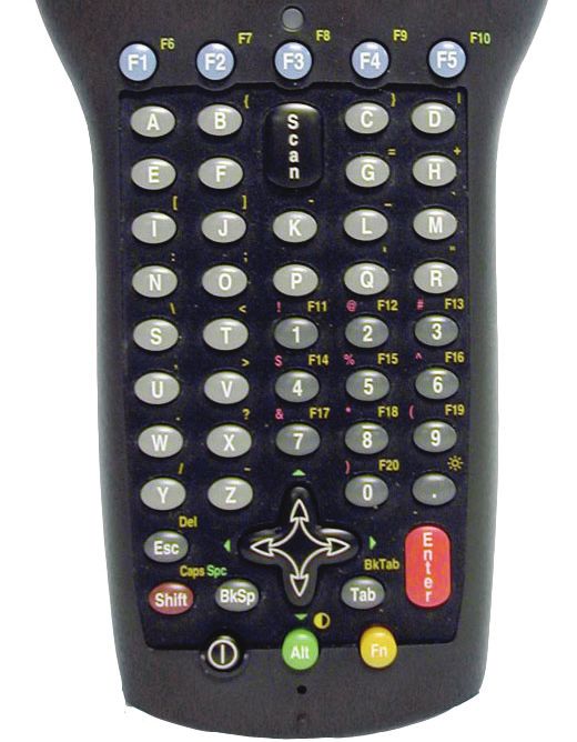
Datalogic Mobile, Inc
1505 Westec Dr.
Eugene, Oregon 97402
Telephone: (541) 743-4800
Fax: (541) 743-4900
An Unpublished Work - All rights reserved. No part of the contents of this documentation or the procedures
described therein may be reproduced or transmitted in any form or by any means without prior written permission of
Datalogic Mobile, Inc. or its affiliates or subsidiaries ("Datalogic" or “Datalogic Mobile”) . Owners of Datalogic prod-
ucts are hereby granted a non-exclusive, revocable license to reproduce and transmit this documentation for the
purchaser's own internal business purposes. Purchaser shall not remove or alter any proprietary notices, including
copyright notices, contained in this documentation and shall ensure that all notices appear on any reproductions of
the documentation.
Should future revisions of this manual be published, you can acquire printed versions by contacting your Datalogic
representative. Electronic versions may either be downloadable from the Datalogic Mobile website
(www.mobile.datalogic.com) or provided on appropriate media. If you visit our website and would like to make
comments or suggestions about this or other Datalogic publications, please let us know via the “Contact Datalogic”
page.
                                                      Disclaimer
Datalogic has taken reasonable measures to provide information in this manual that is complete and accurate,
however, Datalogic reserves the right to change any specification at any time without prior notice.
Datalogic is a registered trademark of Datalogic S.p.A. and the Datalogic logo is a trademark of Datalogic S.p.A. all
licensed to Datalogic Mobile, Inc. All other trademarks and trade names referred to herein are property of their
respective owners.
Falcon® is a registered trademark of Datalogic Mobile, Inc. and of its wholly owned subsidiaries.
Microsoft Windows®, Windows® 2000, Windows®CE, Windows® NT, Windows® XP and the Windows logo are
registered trademarks of Microsoft Corporation.

                                           Patents
This product may be covered by one or more of the following patents:
4,861,972 • 4,866,257 • 4,879,456 • 5,198,649 • 5,208,449 • 5,212,372 • 5,247,161 •
5,311,000 • 5,440,110 • 5,481,098 • 5,493,108 • 5,508,505 • 5,664,231 • 5,671,374 •
5,686,716 • 6,041,374 • 6,412,698 • 6,415,978 • 6,454,168 • 6,478,224 • 6,513,714 •
6,536,670 • 6,561,427 • 6,585,157 • 6,923,377 • 7,108,170 • D377345 • CA2,188,399 • Other
U.S. and Foreign Patents Pending.
Table of Contents

Falcon® 4400 Series with Windows® CE ............................................................. 3
    Overview ......................................................................................................................3
    Getting Started ..............................................................................................................4
    Features of the Falcon ...................................................................................................4
    Powering the Falcon .......................................................................................................8
    Getting Started ..............................................................................................................8
         Battery Pack ...........................................................................................................8
         Power Supply ..........................................................................................................9
         Installing the Battery Pack ..................................................................................... 10
         Checking Battery Power .......................................................................................... 12
         System Tray Battery Status Indicators ...................................................................... 12
         Charging the Batteries ............................................................................................ 13
         Charging with a Battery Charger .............................................................................. 14
         Charging with the Dock ........................................................................................... 14
         Backup Battery ...................................................................................................... 15
         Battery Discharge Characteristics ............................................................................ 15
    Setting Up the Mobile Computer ..................................................................................... 16
         Touchscreen Calibration .......................................................................................... 16
         Getting Connected ................................................................................................. 16
         Setting the Date and Time ...................................................................................... 19
    Entering Data .............................................................................................................. 19
         Using the Stylus .................................................................................................... 20
         Navigating the Display ............................................................................................ 22
         Keypads ............................................................................................................... 24
    Scanning Bar Codes ..................................................................................................... 31
         Laser Scanning ...................................................................................................... 31
         Bar Code Scanning with 2D Imager .......................................................................... 33
    Image Capture ............................................................................................................ 34
    Flash Memory .............................................................................................................. 35
         Saving to Flash ...................................................................................................... 35
         Flash FX Location ................................................................................................... 35
         FlashFX Disk Size ................................................................................................... 36
    Context Sensitive Help .................................................................................................. 37
    Resetting the Falcon ..................................................................................................... 38
         Warm Reset .......................................................................................................... 38
         Cold Reset ............................................................................................................ 39
    Maintaining the Falcon .................................................................................................. 41

Quick Reference Guide                                                                                                            1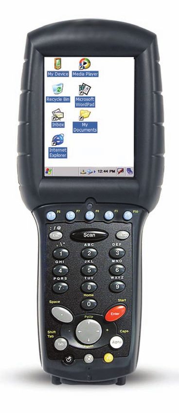
Table of Contents

    Troubleshooting ........................................................................................................... 41
        RF Connectivity Troubleshooting .............................................................................. 45
    Technical Support ........................................................................................................ 46
        Datalogic Mobile Website Support ............................................................................. 46
        Reseller Technical Support ...................................................................................... 46
        Telephone Technical Support ................................................................................... 46
Appendix A: Datalogic Mobile Falcon® Windows® CE Series
   End User License Agreement ....................................................................... 47
Appendix B: Microsoft® Windows® CE
   End User License Agreement ....................................................................... 50
Appendix C: Datalogic Mobile Falcon®
   Windows® CE Product Series Warranty........................................................ 51
Appendix D: Safety Information ........................................................................ 52
    Laser Safety Label ........................................................................................................ 52
        Advisory Statement ................................................................................................ 52
    Regulatory Statements ................................................................................................. 52
        Radio Frequency Interference .................................................................................. 52
        Canadian Compliance Statement .............................................................................. 52
Appendix E: Laser Safety ................................................................................... 53
         English ................................................................................................................. 53
         French .................................................................................................................. 53
         German ................................................................................................................ 54
         Italian .................................................................................................................. 54
         Danish .................................................................................................................. 54
         Dutch ................................................................................................................... 55
         Swedish ................................................................................................................ 55
         Finnish ................................................................................................................. 56
         Norwegian ............................................................................................................ 56
         Portuguese ............................................................................................................ 56
         Spanish ................................................................................................................ 57
         Chinese ................................................................................................................ 57
         Japanese .............................................................................................................. 58

2                                                                        Falcon® 4400 Series with Windows® CE
Falcon® 4400 Series
                                          with Windows® CE

Overview
                  The Falcon® 4400 combines the fle xibility of Windows® CE with the power
                  of the Intel XScale processor, WiFi wireless technology, a large color display,
                  laser (1D) and imaging (1D and 2D) scanning in an ergonomic PDT. The Fal-
                  con® 4400 series is designed for warehouses, distribution centers, retail in-
                  store environments, and other inventory management applications requiring
                  maximum performance and durability.
                  New options available for the Falcon 4400 include 128/128 memory, a full
                  alphanumeric Numbers Up Keypad, and a high-density 2D scan engine.
                  Overmolded models will handle 5’ / 1.5M drops to concrete, and have an
                  IP54 environmental rating; and an 86dBA (at 24") / 100dBA (at 10 cm)
                  beeper. The Falcon® 4400 will handle demanding data collection tasks in
                  industrial environments.
                  The Falcon Management Utility (FMU) and Falcon Desktop Utility (FDU)
                  are included with all units, providing remote management and configurability.
                  This Quick Reference Guide contains the following sections:
                    •   Features of the Falcon on page 4 — describes the functions and keys of
                        the Falcon.
                    •   Powering the Falcon on page 8 — gives information about the batteries,
                        shows how to install the battery pack, and provides options for charging.
                    •   Setting Up the Mobile Computer on page 16 — tells how to calibrate
                        the Touchscreen, set up the radio cards, and set up other options.
                    •   Entering Data on page 19 — using the stylus, navigating the display,
                        about keypads, and bar code scanning.
                    •   Flash Memory on page 35 — about the Flash FX disk.
                    •   Context Sensitive Help on page 37 — accessing Help from the Falcon.
                    •   Resetting the Falcon on page 38 — describes warm and cold resets.
                    •   Troubleshooting and Datalogic Mobile Technical Support on page 41.

Quick Reference Guide                                                                          3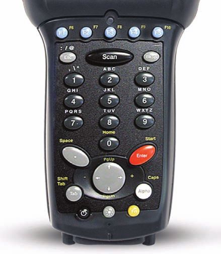
Getting Started

Getting Started
                  Before using the Falcon for the first time, you must install the battery pack
                  into the Falcon, then charge both the battery pack and the backup battery. See
                  Installing the Battery Pack on page 10 for instructions.

                  You must charge the battery pack and backup battery in a dock or with a power
                  cable prior to your first use of the Falcon. The initial charge time is approximately
                  24 hours. See Charging the Batteries on page 13 for more information.
     CAUTION

Features of the Falcon
                  Four perspectives of the Falcon® 4400 mobile computer are shown. Refer to
                  Table 1 on page 7 for a list of the illustrated parts with references to more
                  detailed information.

4                                                             Falcon® 4400 Series with Windows® CE
Features of the Falcon

                  Figure 1. Falcon Front View and Connector View
                                           Touchscreen
                                           Display          USB/Serial Connector

                                                                                    Strap Studs
                                      LED Scanning/                                 w/Rubber
                                      Charging Indicator                            Bumpers

                                     Falcon 44xx                                   Handle
                                     26-Key Key-
                                     pad

                                                                      Falcon 4420
                                                                      Handled model

                                      Power Key
                                   Reset

                  For a complete description of each key on the Falcon, refer to page 24.

Quick Reference Guide                                                                             5
Features of the Falcon

                    Figure 2. Falcon Scanner and Battery Door Views
                   Scanner Aperture
          Stylus

                                           Stylus Holder
                                            Speaker

                                      Trigger

                                      Handle
                                                           Battery Door
                                                           Latch
                                                           (2 each)
                                 Tether/Lanyard Port

                                                Battery Door

                                                                                Strap Studs

                    For more information, please refer to the Falcon® 4400 Windows® CE Mobile
                    Computer Product Reference Guide (PRG), located on the Falcon 4400 Product
                    CD that came with your device.

6                                                                  Falcon® 4400 Series with Windows® CE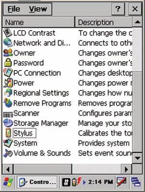
Features of the Falcon

                    Figure 3. Model comparison

                        Model 4410               Model 4420                Model 4420 with Tethered Stylus

Table 1. Features of the Falcon
                                                                                                                 More
     Feature                                    Function/Description
                                                                                                             Information
                   Rotate the latches to unlock the battery door so the battery pack can be                   Figure 4,
  Battery Door
                   removed.                                                                                   page 10
                   The equivalent of a PC monitor for viewing and interacting with the current                Figure 1,
  Display/Touch
                   application. The display is touch-sensitive; use as you would a mouse on a                 page 16,
     Screen
                   PC.                                                                                        page 22
                   The Falcon 442X comes with a handle that is ergonomically designed for
     Handle                                                                                                   Figure 1
                   ease of use with a scanner trigger.
                   Insert an object, such as a paper clip, into this hole to perform a cold reset.
                   Datalogic recommends that you attempt a warm reset first.
    Reset key                                                                                                 page 38
                   Do not use a sharp object, or you could disable the reset function, puncture
                   the keypad’s industrial seal, and void your warranty.
                   Use the alpha-numeric, function, and navigation keys on the keypad to enter
     Keypad                                                                                                   page 24
                   numbers, letters, symbols and navigate with the keypad.
  Lanyard Port     Insert a lanyard to secure a Falcon to a person or work station.                            page 6
Scanner Aperture The laser or imaging scanning beam is emitted from this aperture.                            page 31
                   When scanning, a red LED indicates the laser is on and a green LED indicates a
      LED          good read. When the Falcon is charging in the dock, a red LED on the Falcon indi-          Figure 1
                   cates charging and a green LED on the Falcon indicates fully charged.
                   Press the Power key to turn the Falcon on and off, or to toggle the device                 Figure 1,
   Power Key
                   between suspend (sleep) mode and resume (on).                                              page 24
                   The speaker plays *.WAV and other media files, emits beeps or tones to
     Speaker       indicate errors or good reads when bar code scanning and inputting data                    Figure 2
                   using the keypad or stylus.
   Strap Studs     The Falcon 441X comes with a handstrap that connects to the strap studs.                   Figure 2

Quick Reference Guide                                                                                                     7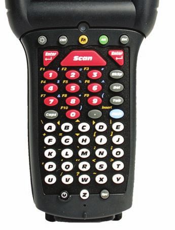
Powering the Falcon

                                                                                                                   More
     Feature                                 Function/Description
                                                                                                               Information
                 Use the stylus for navigation, the soft input panel (SIP), and to select items
                                                                                                                Figure 10,
     Stylus      on the touch screen. Place the stylus in the holder after use so you don’t lose
                                                                                                                 page 20
                 or misplace it. An optional Stylus Tether is available for all models.

Powering the Falcon

Getting Started
                      Before using the Falcon for the first time, you must install the battery pack
                      into the Falcon, then charge both the battery pack and the backup battery. See
                      Installing the Battery Pack on page 10 for instructions.

                  You must charge the battery pack and backup battery in a dock or with a power
                  cable prior to your first use of the Falcon. The initial charge time is approximately
                  24 hours. See Charging the Batteries on page 13 for more information.
     CAUTION

Battery Pack
                      The battery pack in the Falcon is a 3.7 V, 2000
                      mAh Lithium Ion battery pack. You will be                                         3.7V         Product of USA
                      alerted with a message dialog box when the bat-             Li-ion              2000mAh
                                                                                                                       U      S
                      tery pack reaches a low state.
                      After charging the first time, a complete charge                                  5-1764
                                                                                 CAUTION: Battery can explode, leak or catch
                      takes about four (4) hours depending on the bat-           fire if exposed to high temperature, water or fire.
                                                                                 Do not short circuit, open or disassemble battery.
                                                                                 Recycle or dispose of properly.

8                                                                 Falcon® 4400 Series with Windows® CE
Getting Started
tery pack’s state and the recharging method. A sample battery pack label is
shown at the right.
You must charge the battery pack and backup battery in a dock or with a power
cable prior to your first use of the Falcon. The initial charge time is approximately
24 hours.
If you remove the battery pack or it fails, there is a 30 minute window in which to
insert a charged battery pack before the backup battery fails. If your backup bat-
tery fails, the contents of the RAM memory will be lost. If your back-up battery is
less than fully charged, there is a proportionally smaller window of time available.
Usage time will be reduced, also.
CAUTION
Always charge the battery pack within the temperature range of 32°–113°F (0°–
45°C).
Lithium-ion battery packs may get hot, explode, ignite, or/and cause serious injury if
exposed to abusive conditions.
• Do not place the battery in or near fire, direct sunlight, or other high tempera-
ture locations, or heat the battery.
• Do not install the battery backwards so the polarity is reversed.
• Do not connect the positive terminal and negative terminal of the battery to
each other with any metal object (such as wire or coin).
• Do not expose the battery to liquids, or allow the battery to get wet.
• Do not disassemble, modify, or pierce the battery. The battery contains safety
WARNING
and protection devices, which, if damaged, may cause the battery to generate
heat, explode or ignite.
In the event the battery leaks and the fluid gets into your eye, do not rub the eye.
Rinse well with water and immediately seek medical care. If left untreated, the battery
fluid could cause damage to the eye.
Datalogic recommends annual replacement of rechargeable battery packs to
ensure maximum performance.
Power Supply
Use only the authorized power supplies, battery packs, chargers, and docks
supplied by your Datalogic reseller. The use of any other power supplies can
damage the Falcon and void your warranty.
Quick Reference Guide 9Getting Started
Models require either a Listed class II or class III with a Limited Power Source
(LPS). For the safety certification to be valid, class III input power sources
must be IEC/EN60950-1 (EN 60335-series, EN 60065 or relevant) approved.
- For single Docks and battery charger -
Input: 100 - 240 VAC Output: 12 VDC
Max. Current: 2.5 A Max. Power: 30 W
- For 4-slot Docks -
Input: 100 - 240 VAC Output: 12 VDC
Max. Current: 5.0 A Max. Power: 60 W
Installing the Battery Pack
When you first remove the Falcon from the box, you must charge both the
battery pack and the backup battery for a minimum of 24 hours.
Complete the following instructions to install the battery pack:
1. On a 441X, detach the elastic handstrap by releasing its hook from
the strap studs at the base of the unit (refer to the PRG).
10 Falcon® 4400 Series with Windows® CEGetting Started
Figure 4. Installing the Battery Pack
Battery Door Latches
Battery Door
Plastic Pull Tab
Unhook/hook Strap As Needed
Battery
Falcon
Strap Studs
Cover Plate (unit may have Handle here instead)
2. Turn the battery door latches to unlock the battery door. Remove the
door.
3. Insert the battery pack with the pull tab on the outside and the bat-
tery contacts aligned with the matching contacts inside the battery
compartment. The battery pack has a keying feature on one side to
prevent incorrect installation (refer to Figure 4).
4. Replace the battery door by inserting the bottom tab into the slot. If
the battery pack is installed incorrectly, the door will not seat properly.
5. Rotate the battery door latches on the battery compartment cover
towards the base of the unit.
6. On the 441X, replace the handstrap hook on the strap stud at the base
of the unit.
Quick Reference Guide 11Getting Started
Checking Battery Power
If you remove the battery pack or the battery fails, you have about 30 minutes
to swap in a new battery pack or charge the battery pack before the backup
battery fails (if the backup battery has been fully charged).
System Tray Battery Status Indicators
The System Tray displays icons to show the status of some battery conditions,
as shown in Table 2.
Table 2. System Tray Battery Status Indicators
Battery Status Icons
Battery Status Icon Description
Backup
Battery Low no icon The battery status is updated in the control panel, but no icon is displayed.
Condition
Backup When the backup battery is very low, the system tray contains a very low backup
Battery Very battery CAUTION icon. In addition, a dialog box pops up and alerts you that the
Low Condition backup battery is very low and needs to be charged. The dialog comes up every five
minutes until you charge the backup battery.
Battery
Charging This icon indicates that the battery pack is currently charging.
Condition
Battery Low
Condition This icon indicates that the battery pack is low.
Battery Very When the battery pack is very low, the system tray shows a very low battery CAU-
Low Condition TION icon. Also, a dialog box pops up and alerts you to charge the battery pack. A
battery warning dialog will pop up every five minutes until you charge the battery.
Main batteries
Battery Power The Power control applet displays a battery power gauge.
Remaining power:
Gauge 0 100 Start > Settings > Control Panel > Power.
Discharged When the battery is totally discharged, the battery sensor initiates a shutdown of all
Battery applications, and closes the RF Network connection. If the battery pack has com-
Condition pletely discharged, when the battery pack is charged or replaced, the unit will
no icon
resume as before after a cold reset.
Refer to Flash Memory on page 35 regarding the data loss of applications and data
stored in RAM.
12 Falcon® 4400 Series with Windows® CEGetting Started
Charging the Batteries
There are several methods for charging the battery pack and backup battery.
LEDs on the Falcon, the Single-Slot Dock, Four-Slot Dock, and Four-Slot
Battery charger give visual indication of the charge state. Table 3 gives an over-
view of all the LEDs and what they indicate.
Table 3. Battery Charging Methods and Indications
PDT Charge LED Spare
PDT
Charge Battery
LED Charge
LED
Charging Location: Charge Indicator LEDs
Falcon seated in a Falcon connected Charging slot of
Four-Slot Battery
Dock (Single or to an external Dock (Single or
Charger
Four-Slot) power supply Four-Slot)
Charging Duration 4-6 hours 4-6 hours 3-5 hours > 3 hours
Battery Pack Charge
Indication: Charging: RED Charging: RED
Fully Charged: Fully Charged: N/A N/A
Falcon Charge LED GREEN GREEN
Charging:
Solid RED Charging:
Dock or Charger
Fully charged: LEDs are AMBER
Battery Charge No effect No effect
GREEN Fully charged:
LED(s)
*Fault: LEDs are GREEN
Flashing RED
Simultaneously
Charges YES YES NO NO
Backup Battery?
* Refer to page 45 for more information.
Quick Reference Guide 13Getting Started
Charging with a Battery Charger
A LiIon Four-Slot Battery Charger is available to charge batteries indepen-
dently from the Falcon. To use, align the battery contacts with those in the
Charger and insert them into the slots.
Figure 5. Four-Slot Battery Charger
Power Indicator LED
Charging with the Dock
There are two models of docks for the Falcon: a Single-Slot Dock and a Four-
Slot Dock. On both models, an external power supply (AC adaptor) provides
power to the dock. Falcons communicate with the host PC using Microsoft
ActiveSync protocol either via a USB port or via a serial port.
There are two methods for charging a battery pack using a Single-Slot Dock.
Refer to Table 3 on page 13 to view methods of battery pack charging using
the dock, charge duration, dock status indicators and their purpose. For more
information on the dock, refer to the Dock Operating Instructions that come
with each dock.
Use only the correct battery chargers and docks with this Windows CE color Fal-
con. This technology used for these models is incompatible with other Datalogic
Mobile Falcon chargers and docks, including the Falcon 4410/4420 monochrome
models.
14 Falcon® 4400 Series with Windows® CEGetting Started
Figure 6. Charging the Battery Pack in a Single-Slot Dock
Top/Rear View of Single-Slot Dock
USB/Serial Connector Battery Pack in
Spare Battery
Battery Pack in Charging Slot
Spare Battery
Charging Slot
Power Port
Battery Tab
RS-232 Serial Port
USB Port
Power LED
Spare Battery LED
Refer to Table 3 on page 13 for a list of LED indicators and their purpose.
Refer to the PRG for additional information on storage and disposal of batter-
ies.
Backup Battery
The 3V Lithium Backup Battery receives its charge from the Battery Pack. To
retain date, time, data, and other settings for the Falcon, maintain at least a
minimal charge on the Battery Pack.
When the backup battery is low, an icon will display on the status bar (see
Table 2 on page 12), and a dialog box will open to alert you.
Battery Discharge Characteristics
Battery discharge characteristics vary from eight to nine and a half (8-9.5)
hours, depending upon device usage, number of scans per minute, backlight
usage, and other factors that draw upon battery power.
Quick Reference Guide 15Setting Up the Mobile Computer
Setting Up the Mobile Computer
At first use or after a cold reset, the unit will go through a series of initial
bootup sequences. Each of these sequences are described as noted:
1. Touchscreen Calibration, illustrated in Figure 7.
2. Getting Connected on page 16.
3. IP Network Setup on page 17.
4. Setting the Date and Time on page 19.
Touchscreen Calibration
Figure 7. Touchscreen Calibration
Follow the on-screen directions to cali-
brate the touchscreen.
For more information on touchscreen
calibration, refer to the PRG.
Getting Connected
Bluetooth Setup
1. Open the Bluetooth control panel at Start > Settings > Control Panel >
Bluetooth Manager.
2. Search for available Bluetooth Devices by tapping the button for the
type of device you want (Printer, Serial or All) .
3. Create a pairing by double tapping the listing for the device you want
and selecting the service. If you want to specify encryption or require
authentication, enable the appropriate checkbox.
4. Tap OK to complete.
16 Falcon® 4400 Series with Windows® CESetting Up the Mobile Computer
For detailed instructions, reference the PRG.
Connecting to a PC
In order for the Falcon to communicate with a host PC, Microsoft® ActiveSync must
be installed on the computer. Go to www.microsoft.com/downloads/ for information.
Reference the PRG for detailed instructions.
Installing the USB Driver
So the Host PC can communicate with the Falcon, install the USB driver file
from the CD that came with the Falcon, or download it from the Datalogic
website. Follow the directions on the CD, or use the following instructions:
1. Microsoft® ActiveSync must be installed on your computer before pro-
ceeding. Go to www.microsoft.com for information.
2. Copy the current USB driver file from the Falcon CD to the C:\Pro-
gram Files\Microsoft ActiveSync\Drivers.
3. Connect the USB cable to the Falcon or place the Falcon in the dock.
4. Connect the USB cable to the Host PC.
5. Follow directions on screen. The specified source directory is the one
identified in step 2.
Serial Cable Setup
1. To connect the Falcon using a Serial cable, go to Start > Settings > Control
Panel > PC Connection.
2. If not already checked, select Enable direct connections to the desktop com-
puter.
3. Tap Change Connection and select Serial from the dropdown box.
4. Tap OK.
IP Network Setup
1. Select Start > Settings > Network and Dialup Connections.
2. Double-tap on the item (varies based on the radio installed and the number of
connections).
3. Complete the two tabs (shown in Figure 8):
Quick Reference Guide 17Setting Up the Mobile Computer
Figure 8. Modifying Network Connection Settings.
• IP Address: Select DHCP or set static IP settings.
• Name Servers: If using static IP, set DNS and WINS servers.
RF Setup (Summit Client Utility)
The Summit Client Utility (SCU) is an application designed for users and administra-
tors of mobile devices that use a Summit radio module. Using SCU, you can:
• Disable and enable the radio (turn it off and on)
• View the contents of configuration profiles, or configs, each of which houses
the RF, security, and other settings for the radio
• Select the config to be used to connect to a WLAN
• View global settings, which apply to every config
• View status information on the radio, the access point (AP) or WLAN router to
which it is connected, and the RF connection or link between the two
• Troubleshoot a connection or performance issue, view in-depth diagnostic
information on the connection and the radio, and perform various trouble-
shooting and diagnostic tests
1. To launch the utility, go to Start > Settings > Control Panel.
2. Tap on the Wi-Fi icon.
For more detailed information on making changes to settings, please refer to the PRG.
18 Falcon® 4400 Series with Windows® CEEntering Data
Setting the Date and Time
To set or change the date and time, complete the following steps:
Figure 9. Setting the Date and Time
1. From the Start menu, select Settings >
Control Panel > Date/Time to open the
Date/Time Properties control panel.
Use the arrows in the application to
navigate, increase or decrease the
time or date.
2. Select the year to open a field where
you can change the year by backspac-
ing, or entering a new year.
3. Select the month to open a pull-
down list of months.
4. Tap the checkbox to Automatically
adjust clock for daylight savings time, if
desired.
Entering Data
To open applications, select Start > Programs to display a list of available pro-
grams. If the program has an icon on the desktop, double-tap to open it.
There are several ways to enter data with the Falcon:
• Use the keypad. Refer to Keypads starting on page 24.
• Use the stylus on the touchscreen display. Refer to Using the Stylus on
page 20 for more information on using the stylus.
• Use the soft input panel (digital keyboard) with the stylus. Refer to
Soft Keypad/Input Panel on page 23.
• Select text in the same way you select text on a PC. Use the stylus to
highlight the desired text by dragging the stylus across the desired
text, double-tapping to select one word, and triple-tapping to select
an entire line.
• Use the bar code scanner to enter data. Press the trigger or scan button
to initiate a scan. The scanned data will be entered into the current
Quick Reference Guide 19Entering Data
application’s open file. Refer to Scanning Bar Codes starting on
page 31 for more information on using the scanner.
• If your Falcon has the 2D Imaging module installed, you can read and
decode traditional 1D linear bar codes, 2D and composite symbols.
You can also capture images such as signatures, labels, and other items.
See Bar Code Scanning with 2D Imager starting on page 33 for fur-
ther information.
Using the Stylus
Never use a pen, pencil, or other sharp object on the Falcon’s touchscreen dis-
play. Use only the supplied stylus or plastic-tipped pens intended for use with a
touch-sensitive display. Contact your reseller to replace a missing stylus; refer to
the Datalogic Mobile website listed on the back cover of this manual.
The stylus is located next to the scanning pod as illustrated in Figure 10. The
stylus on the Falcon is the equivalent of the mouse on a PC. Use the stylus to:
• Navigate the touchscreen display.
• Select characters in the soft input panel (SIP).
• Select applications from the desktop or system tray.
• Select tabs, fields and text within applications and dialog boxes.
Figure 10. Back View of a Falcon 4420 with a Stylus
Stylus Stylus Holder
20 Falcon® 4400 Series with Windows® CEEntering Data
It is good practice to replace the stylus into the holder after each use so you
don’t misplace it. An optional Tethered Stylus is also available, preventing acci-
dental loss of the stylus.
Figure 11. Tethered Stylus
Tethered Stylus
Quick Reference Guide 21Entering Data
Navigating the Display
There are several navigation areas on your display, including the command bar,
and task bar. Each of these navigation areas have sub-areas of navigation as
well. Take the time to familiarize yourself with these features to save yourself
valuable time.
The Command Bar
Use the Command bar at the top of the screen to perform tasks in programs,
such as opening a file, saving a file, or editing a file. Refer to Figure 12, to view
the Command bar.
Figure 12. Application Navigation
Command Bar (Top)
Desktop
Application Icons
System Tray
Navigation Arrow
Battery Charging Indicator Network Connection
Keyboard Indicator Soft Input Panel
Task Bar (Bottom)
Active Application Window Extras Menu Button (Open Applications)
Start Button
22 Falcon® 4400 Series with Windows® CEEntering Data
The Task Bar
The Task bar at the bottom of the screen displays the start menu icon, an icon
for the active program, the current time, and system icons for utilities loaded
in memory, including the keyboard icon, which opens and closes the soft
input panel (SIP).
Start Button. Tap the Start button ( ) to open the Start menu. The Start
menu includes access to Programs, Favorites, Documents, Settings, Help, and the
Run command. From Settings you can access the Control Panel, Network and
Dial-up Connections, and the Taskbar and Start Menu configuration.
System Tray. The System Tray contains icons for key presses, utilities and
applets running in the background. Tap the small arrow(s) in the System Tray
to view icons for current input mode(s), keypress, power management, and
network connections.
Soft Input Panel. Refer to Soft Keypad/Input Panel, below, for details.
Extras Menu. Tap the Extras Menu button at the far right of the Task bar to
select from a list of open applications or to access the desktop while leaving a
program open.
Soft Keypad/Input Panel
In applications that accept keyed input, the soft input panel (SIP) can be used
to enter data using the stylus. The SIP is a digital, QWERTY-style keyboard.
Figure 13. Soft Input Panel
Keyboard Icons
Soft Input Panel
Quick Reference Guide 23Entering Data
To open the SIP: Tap the Keyboard icon to open the menu and select Key-
pad from the pop-up menu to open the keyboard
To close the SIP: Tap the Keyboard icon to open the menu and select Hide
Input Panel to close the keyboard
Use the stylus to select letters, numbers, or symbols from the Soft Input Panel
for the current application. Tap the key to change the keypad to show
international letters.
Keypads
Overview
The Falcon is available with several different keypad models:
• 26-Key Keypad on page 27
• 48-Key Keypad on page 28
• 52-Key Keypad on page 29
• 52-Key Numbers Up (NU) Keypad on page 30
• 5250 Keymap on page 30
Refer to the PRG for information on configuring the keypads.
Keypad Attributes
There are a number of keys that are common to the different keypad models.
Table 4 lists special function keys that are found on several keypads, as well as
those which are unique to specific keypads.
Table 4. Keypad Overview - Special Keys
Key Name Keypad Model(s) Function/Description
Press to access lower case alpha characters and symbols on the
26-key
26-key keypad.
Alpha- In Normal mode, use the alpha-numeric keys to enter numbers and letters.
Numeric All In Shift and CAPS modes, the alpha-numeric keys enter upper case let-
Keys ters.
Backlight All toggles the Backlight on or off when you press it.
Press to enter the FN input state. Use FN mode to access additional
All
features and operations.
Press Power to put the Falcon into sleep (suspend) mode if it is currently
All running, and wake up (resume) the Falcon if it was in sleep mode. Press
and hold it briefly to turn off the Falcon.
24 Falcon® 4400 Series with Windows® CEEntering Data
Key Name Keypad Model(s) Function/Description
26-key
52-key Press to activate the laser scanner.
52-key NU
Press the edge of the 4-way rocker key to move the cursor or highlighted
4-Way text entry during a menu/list selection. In a text window:
26-key • The arrow moves the cursor up one line.
Rocker
52-key • The arrow moves the cursor to the right one character.
Key
• The arrow moves the cursor down one line.
• The arrow moves the cursor to the left one character.
allows keyboard shortcuts like a PC. You can perform functions
48-key
such as Save (Ctrl-s) and Find (Ctrl-f). Toggle on and off for text formatting
52-key NU
(for example, Ctrl-b for bold, Ctrl-i for italics, Ctrl-u for underline).
48-key
Press to enter the Alt input state. Use Alt mode to access application
52-key
menus.
52-key NU
48-key
Press to enter Shift input states. Use Shift mode to output upper-
52-key
case characters and punctuation (identified over number keys).
52-key NU
System Tray Keyboard Indicators
The System Tray Keyboard Indicators are located at the bottom of the display
in the Task bar. The most recently activated state is in the left position if more
than one state is active.
• The icon is displayed if either Shift or CAPS mode is active.
• If more than two states are active at the same time, only the last two
states are displayed in the System Tray.
Scroll between icons to view the active modes.
Table 5. Input States and their System Tray Indicators
Keypad
Icon State Function
Model(s)
Normal
Present only on keypads with an Alpha key. It appears when Alpha or CAPS
(Numeric) 26-key
modes are not on.
Mode
Quick Reference Guide 25Entering Data
Keypad
Icon State Function
Model(s)
Press to enter lower case alpha characters and symbols. When in Alpha
mode, the current alpha character is displayed by a system tray keyboard indica-
Alpha tor.
26-key
Mode
Alpha mode is persistent, which means that the system stays in Alpha mode until
you press again.
Press + to activate CAPS mode. CAPS mode generates upper
case alpha characters A-Z.
26-key
CAPS mode is persistent; press + again to generate lower case
characters. Punctuation keys are not affected.
CAPS
Press + to activate Caps mode. Caps mode generates upper
Mode
48-key case alpha characters A-Z.
52-key
CAPS mode is normally persistent; you must press + again to
52-key NU generate lower case characters. Punctuation keys are not affected. If CAPS is
active, and SHIFT is active, no icon is displayed.
Press to enter FN mode.
26-key is independent of the key. Use FN mode to access the features
and operations on the keypad.
Fn Mode
48-key
52-key Fn mode converts alpha keys to punctuation and function keys. Fn mode is acti-
vated by pressing .
52-key NU
Shift mode converts characters to upper-case letters or punctuation. Activated by
48-key pressing . This state expires after a normal key is pressed unless the
Shift 52-key key is held down.
Mode
52-key NU Toggles to make the next alpha character capitalized. If Shift state is active when
the Caps State is active, no icon is displayed.
48-key Alt mode converts keys to system keys that allow users to access the menu. Acti-
Alt Mode 52-key vated by pressing . This state expires after a normal key is pressed unless
52-key NU the key is held down.
48-key allows keyboard shortcuts. You can perform functions such as Save (Ctrl-
Ctrl Mode s) and Find (Ctrl-f). Toggle on and off for text formatting (for example, Ctrl-b for
52-key NU bold, Ctrl-i for italics, Ctrl-u for underline).
26 Falcon® 4400 Series with Windows® CEEntering Data
26-Key Keypad
The 26-key keypad is organized like a cell phone, with multi-tap access to
alpha characters on numeric keys (see Figure 14). Use the ten (10) alpha-
numeric keys and the key to type letters, numbers, and symbols listed in
Table 6 on page 28.
Figure 14. 26-Key Keypad
Scan
Esc BkSp
. (Space) Enter
Tab Alpha (Caps)
Fn
Power
Backlight
26-Key Functions. Most of the keys on the keypad of the Falcon have more
than one function. To access the secondary features and functions, you must
first press another key to access the desired input state.
Only one system tray icon is visible at a time. The most recently activated state
is in the left position of the system tray if more than one state is active.
Alpha-Numeric Keys. Press the keys in Table 6 once, twice, or more times
to cycle through the alpha letters and symbols until the desired character
appears in the system tray. After the last letter or symbol in the sequence for
that key, the next keypress will generate the first letter or symbol in the
sequence.
Quick Reference Guide 27Entering Data
Table 6. 26-Key Keypad Alpha Characters and Symbols
Normal
Alpha Mode
Mode
First Second Third Fourth Fifth
Key
Keypress Keypress Keypress Keypress Keypress
: / @ : /
, \ * , \
A B C A B
D E F D E
G H I G H
J K L J K
M N O M N
P Q R S P
T U V T U
W X Y Z W
48-Key Keypad
The 48-key keypad is designed to allow you to type all letters and numbers
without requiring multiple key presses.
Figure 15. 48-Key Keypad
Backlight Esc
Shift Alt
(Caps) Fn
Ctrl
Power
Some of the keys on the 48-key keypad of the Falcon have more than one
function. To access the secondary features and functions, you must first press
28 Falcon® 4400 Series with Windows® CEEntering Data
another key to access the desired input state. See Table 4 on page 24 for fur-
ther information.
48-Key Functions
Press the key to toggle the backlight on or off. To adjust the bright-
ness press . Press to accept the changes.
48-Key Input States
The input states for the 48-key keypad are , , , , and
. Each state is described in Table 5 on page 25.
52-Key Keypad
The standard 52-key keypad is designed to allow you to type all letters and
numbers without requiring multiple key presses.
Figure 16. 52-Key Keypad
Scan
. (Backlight)
Shift
Power Fn
Alt
Some of the keys on the keypad of the Falcon have more than one function. To
access the secondary features and functions, you must first press another key to
access the desired input state. See Table 4 on page 24 for more information.
Quick Reference Guide 29Entering Data
52-Key Functions
Press +< . > (period/decimal) to toggle the backlight on or off. To adjust
the contrast, press + or select Start > Settings > Backlight. Press
to accept the changes.
Accessing FN and ALT Modes
The input states for the 52-key keypad are , , , and .
Each is described in Table 5 on page 25.
52-Key Numbers Up (NU) Keypad
The full alphanumeric 52-Key Numbers Up (NU) keypad brings frequently
used keys into a more ergonomic position, and is available with the 5250 TE
overlay.
Figure 17. 52-Key NU Keypad
Fn Alt
Backlight Esc
Ctrl Scan
Caps Shift
Power Space
5250 Keymap
The 5250 keymap is designed to provide the keyboard functions needed to
run 5250 terminal emulation software.
The 5250 keymap is available with either the 48-key, 52-key, or 52-key NU
model.
30 Falcon® 4400 Series with Windows® CEScanning Bar Codes
Figure 18. 5250 Keymap for the 52-Key Keypad
Scan
. (Backlight)
Shift
Power Fn
Alt
Scanning Bar Codes
Laser Scanning
To use the scanning function on units containing a laser scanning module,
complete the following steps:
1. Select and open a bar code application, such as Microsoft® WordPad.
Quick Reference Guide 31Scanning Bar Codes
Figure 19. Scanning a Bar Code
Press on the keypad (26, 52 or 52-key NU)
or the Scan Trigger to initiate a scan with the Falcon.
2. Aim the scan window at the bar code following the guidelines outlined
in Figure 20.
3. Press on the keypad (26, 52 or 52-key NU) or the Scan Trigger
on the handle. The laser scans as long as you hold the button or trigger,
or for 10 seconds, or until a good scan is obtained.
4. Aim the laser beam at the center of the bar code.
• Position the unit close to bar code when scanning small bar codes.
• Position it at a distance when scanning larger bar codes.
• The laser is disabled after you release the key or after 10 seconds,
or once a good scan is obtained.
Figure 20. Laser Beam Positions
Correct Scanning Positions
Ideal positioning A bit high, will read correctly A bit angled, will read correctly
Incorrect Scanning Positions
Too angled; cannot read the Bar code will not read. The
Positioned too far to the right. Will
entire bar code. scanner should be posi-
not read entire bar code.
tioned perpendicular to
the bar code bars.
32 Falcon® 4400 Series with Windows® CEScanning Bar Codes
5. The device beeps and the green LED indicator comes on until the trig-
ger is released. The green LED and the beep tone indicate a good read.
If the bar code scan failed, adjust the reading angle or distance. Make sure that
the laser beam scans across all bars of the bar code. Refer to Figure 20.
6. The bar code data is entered in the current application.
7. Once a bar code is read successfully, the scanner turns off automatically.
Refer to the section on Scanner Configuration in the PRG to modify the
default settings.
Bar Code Scanning with 2D Imager
Scanning bar codes with the 2D imaging device is similar to scanning with a
laser scanner. The operation and configuration of the scanner is performed in
the same way as laser scanning devices. Trigger behavior and scanning time-
outs are the same as laser scanning devices.
Scanning Differences
Scanning Aimer
The imager contains an aiming beam rather than a red laser. The aiming beam
mimics a laser line for purposes of orienting the imager to a bar code. Figure
21 shows how the aiming beam visually differs from the laser beam in laser
scanning devices.
Figure 21. Laser vs. Imaging beam
Laser Aiming Beam
Note that the aiming beam for the imager is green, rather than red.
Quick Reference Guide 33Image Capture
Orientation
Rotational orientation does not affect the imager module's ability to read bar
codes. For example, the imager can read a bar code when the aimer beam is
parallel to the lines of the bar code. What is important is the location of the
aimer in relation to the center of the bar code. The aiming beam should be
centered over the bar code, but it can be positioned in any direction for a good
read.
Figure 22. Aiming Beam Positioning
Linear bar codes 2D Matrix symbol
The aiming beam is smaller when the imager is closer to the code and larger
when it is farther away. Symbologies with smaller bars or elements (mil size)
should be read closer to the unit. Symbologies with larger bars or elements
(mil size) should be read farther from the unit. To scan a label, hold the imager
at an appropriate distance from the target, pull the trigger, and center the aim-
ing beam on the symbol.
Scanning Illumination
Another feature that can be enabled for 2D scanning is an array of illumina-
tion LEDs. These LEDs provide illumination in dark environments and can
improve scanning performance under certain lighting conditions. By default,
the illumination LEDs are turned on. Illumination LEDs can be disabled
using the PDT parameters. See the PRG for complete information on pro-
gramming the LEDs.
Image Capture
The 2D imager can be used for capturing, manipulating, and transferring
images.
34 Falcon® 4400 Series with Windows® CEFlash Memory
You can set options for image capture in the Imaging Control Panel. Various
image formats can be selected, including TIFF, JPEG and BMP. You can also
scale, rotate, and modify image quality settings. See the PRG for detailed infor-
mation on using the Falcon 2D for image capture.
Flash Memory
In addition to the RAM-based storage standard on Windows CE terminals,
the Falcon is also equipped with Datalight FlashFX Flash-based application
and file storage area. Refer to the PRG for more information.
The FlashFX storage memory persists across all reset (warm/cold reboot) condi-
tions and software / firmware updates.
Because of this, Datalogic very strongly recommends installing all applications,
applets, programs, and important data files to the FlashFX disk of the Falcon.
If an application or a data file is only installed or saved in RAM, a hard reset will
result in the loss of that application or data file.
Saving to Flash
To save an application or data to the Flash Memory, from your current appli-
cation, select File > Save As > navigate to the FlashFX Disk location as described
below.
Flash FX Location
To access the contents of Flash Memory:
1. Double-tap the My Device icon on the desktop.
2. Double-tap the FlashFX Disk icon to view the FlashFX Disk.
Quick Reference Guide 35Flash Memory
Figure 23. Location of the FlashFX Disk
FlashFX Disk Size
The size of the FlashFX disk will vary, depending upon several factors, such as
the size and number of currently running applications and the amount of
memory currently consumed by the OS.
To view the current size of Flash Memory:
1. Double-tap the My Device icon on the desktop. (See Figure 23).
Figure 24. Size of FlashFX Disk
A B
36 Falcon® 4400 Series with Windows® CEContext Sensitive Help
2. Press and hold the FlashFX Disk directory with the stylus, and select
Properties from the pop-up menu (see Figure 24A).
3. The FlashFX Properties dialog opens (see Figure 24B). The number
following Free is the amount of memory currently available on the
Falcon.
Table 7. FlashFX Disk Specifications
FlashFX Disk Specifications
Total Flash size 64.0 MB 128 MB
OS/Firmware uses up to 32.0 MB 32 MB
FlashFX size 32.0 MB 96 MB
File storage size 31 MB (approximate) 90 MB (approximate)
Running Application 22 MB (approximate) 81 MB (approximate)
Context Sensitive Help
Microsoft Windows CE context sensitive help is available wherever a “?” but-
ton appears in the upper right hand corner of the window. Press the “?” button
to open the context help window.
Figure 25. Using Windows CE Context Sensitive Help
To open context sensitive Help, select/tap the “?” in the upper right corner of
most screens. Select/tap the desired item from the list of hot links.
Quick Reference Guide 37Resetting the Falcon
Resetting the Falcon
There are two reset methods for the Falcon.
• A warm reset terminates a “hung” application, and clears the working
RAM, but preserves the file system.
• A cold reset forces all applications to close and clears working RAM
and files not resident on the FlashFX Disk.
Datalogic recommends that you always attempt a warm reset before initiating a
cold reset. Once you initiate a cold reset, all applications are forcibly closed and
working RAM and files are cleared.
It is a good idea to store important data in FlashFX storage for this reason. Refer
to Flash Memory on page 35 for more information on Flash Memory.
CAUTION DO NOT use a sharp object on the reset button. Sharp objects can puncture the
keypad, disabling the reset function, rupturing the Falcon’s industrial seal, and
voiding your warranty.
Warm Reset
A warm reset is a transition from the on or idle condition that closes all appli-
cations, clears the working RAM, but preserves the file system.
If an application “hangs,” initiate a warm reset to terminate the application.
Procedure to Warm Reset
The reset procedure varies, depending upon the keypad on your Falcon. The
first two keys of the sequence can be pressed in any order, but the unit will not
reset until they both are held down and then the third key (, or
) is pressed. All three keys must be held down for the unit to reset. Refer
to Figure 26 on page 39 for the location of the reset keys.
26-Key Falcon. Press and hold: ++.
48-Key Falcon. Press and hold: ++.
52-Key Falcon. Press and hold: ++.
52-Key NU Falcon. Press and hold: ++.
38 Falcon® 4400 Series with Windows® CEResetting the Falcon
Figure 26. Warm Reset
Hold down 1 & 2 ...then press 3
F1 F2 F3 F4 F5
1 2
: /@
3 3
Ctrl Fn Alt Esc
E sc S can B kS p
, \*
Enter Enter
A B C D E F Scan
1 2 3
1 2 3 BkSp
G H I J K L M N O
4 5 6
4 5 6 Del
3
P Q R S T UV W XY Z 7 8 9 Tab
7 8 9 2 Caps 0 . Shift
H om e A B C D E
S pace S tatr
0 F G H I J
. E n te r
K L M N O
3 P Q R S T
S h ift C aps
Ta b U V W X Y
Ta b A lp h a
2 Z Spc
Fn
1
1
1 2
26-Key 48-Key 52-Key / 5250 52-Key NU
After Warm Reset
• The splash screen will appear briefly.
• The desktop appears with the application shortcuts on the screen.
• RF Network PC Card (if present) connects to the network system.
The custom settings in the registry are persistent.
Cold Reset
A cold reset is a complete reset of the Falcon in which all applications are forc-
ibly closed and working RAM is cleared.
Quick Reference Guide 39Resetting the Falcon
Datalogic recommends that you always attempt a warm reset before initiating a
cold reset. Once you initiate a cold reset, all applications are forcibly closed and
working RAM and files are cleared.
Any applications, files, or data in RAM will be lost if you cold reset. Only the appli-
cations and the files in the FlashFX Disk are preserved upon a cold reset. Refer to
Flash Memory on page 35 for more information on preserving applications and
CAUTION files with the persistent FlashFX storage memory.
Do not use a sharp object on the cold reset button as this can puncture the key-
pad, disabling the reset function, rupturing the Falcon industrial seal, and voiding
your warranty. Datalogic recommends using a straightened paper clip.
Reason to Cold Reset. Press the button when the Windows CE
operating system locks up and the warm reset command does not work.
Procedure to Cold Reset. To perform a cold reset, insert a paper clip into
the cold button while pressing the button (refer to Figure 27).
Figure 27. Cold Reset
: /@
Esc Scan BkSp
, \* ABC DEF
1 2 3
GHI JKL MNO
4 5 6
PQRS T UV W XY Z
7 8 9
Home
Space Start
0
. Enter
Shift Caps
Tab
Tab Alpha
Cold Reset
Fn Button Access
After Cold Reset
When a Falcon goes through the cold reset sequence, it clears the working
RAM and initializes the file system. You will lose any applications and data
which are not stored in persistent flash memory (refer to Flash Memory start-
ing on page 35).
40 Falcon® 4400 Series with Windows® CEMaintaining the Falcon
• The splash screen will appear after a short period.
• Recalibrate the touch screen or press to circumvent calibration.
• The desktop appears with the application shortcuts on the screen.
• RF Network PC Card (if present) connects to the network system.
The custom settings in the registry are persistent.
Maintaining the Falcon
With normal use, the Falcon, Dock, Four-Slot Dock and battery chargers
require no maintenance. For trouble-free service, observe the following tips
when using the Falcon:
• To prolong its life and avoid problems, keep the Falcon clean. Use a
clean, soft cloth dampened with a mild, dilute cleanser.
• If you need to clean the display, clean it with a lens cloth or other soft
cloth dampened with a mild, dilute cleaning solution.
Never use a pen, pencil, or other sharp object on the display/touch screen.
Use only the supplied stylus or plastic-tipped pens intended for use with a
touch-sensitive screen.
CAUTION Do not immerse the Falcon, docks, or battery chargers in liquid.
Do not use abrasive paper/cloth or abrasive/corrosive cleaners to clean the
unit.
Do not use a sharp object to Reset; use a paper clip. A sharp object can
puncture the keypad, disabling the reset function, rupturing the industrial
seal, and voiding your warranty. Refer to the Falcon 4400 Quick Reference
Guide for reset instructions.
WARNING
Troubleshooting
Refer to the Falcon 4400 Windows CE PRG for more information.
Quick Reference Guide 41You can also read