Fast Fire Rapid Log Splitter - en - Forest Master
←
→
Page content transcription
If your browser does not render page correctly, please read the page content below
Fast Fire
Rapid Log Splitter
Model: FMFF (6 & 8 Ton / Electric & Petrol)

                                                                 en

IMPORTANT: Read this manual fully before assembly and use, and
observe all safety rules and operating instructions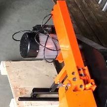
Technical Specification                               3
                Safety                                                4
                Assembly                                              7
                Know Your Log Splitter                                18
     Contents

                Operation                                             19
                Maintenance                                           22
Contents

                FAQ / Fault Finding                                   22
                Exploded View                                         23
                Parts List                                            24
                Warranty                                              26

                The Forest Master Fast Fire Log Splitter is a kinetic log splitter that produces either 6 or
                8 tons of splitting power, capable of splitting both seasoned and unseasoned wood. This
                is an electric log splitter, but it can also be fitted with either a Forest Master FM139 or a
                Honda GX35 petrol engine, which will eliminate the need for wires and cables.

                The the electric motor or petrol engine powers the kinetic device that ensures an efficient
                and fast split of wood, including hard knotty wood. Using the latest kinetic technology,
                the Forest Master log splitter uses the motor to power a single flywheel system that stores
                energy and then releases it in one quick burst, which maximises efficiency of splitting the
                log. This dramatically reduces the cycle time of the splitter to 3 seconds, allowing you to
                split more wood in less time.

                The kinetic log splitter is capable of splitting logs up to 520mm in length and 400mm in
                width. Unlike standard log splitters, this machine has an automatic belt tension system so
                you don’t need to tension the belts. In order to comply with the latest safety regulations,
                this splitter is operated by both hands simultaneously, one hand to press the push button
                and the other to operate the control handle. This ensures that your hands are clear of all
                moving parts during the splitting operation. It is also fitted with a work bench and safety
                guard.

                This log splitter comes with a stand that has wheels at the rear and locking castors at the
                front, so it can be moved easily around a job site or workshop.

                CE APPROVAL Parts
                In order to comply with CE Approval regulations within the UK and European Union, the
                log splitter is supplied with a work bench and safety guard. Outside of these areas the
                user can choose not to fit the safety guard to the work bench.

    2                                                                 FM6FF & FM8FF (Electric & Petrol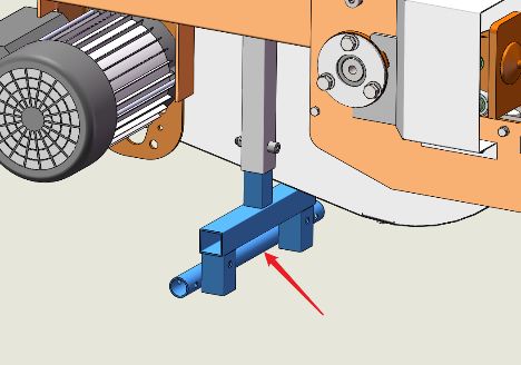
Model (Electric)                      FM6FFE                FM8FFE

                                                                                       Technical Specification
Minimum log diameter                  50 mm                 50 mm
Maximum log diameter                  400 mm                400 mm / 500 mm*
Maximum Log Length                    520 mm                520 mm
Motor                                 230V 50Hz             230V 50Hz 2200W
                                      2200W IP54            IP54
Flywheel Weight                       15 kg                 19.5 kg
Rotational Speed                      465 rpm               465 rpm

                                                                                      Safety
Splitting Force                       6ton                  8 ton
Length                                1720 mm               1720 mm
Width                                 710 mm                710 mm
Height                                1230 mm               1230 mm
Weight                                85 kg                 90 kg

Model (Petrol)                        FM6FF-HTW /           FM8FF-HTW /
                                      FM6FF-139             FM8FF-139
Minimum log diameter                  50 mm                 50 mm
Maximum log diameter                  400 mm                400 mm / 500 mm*
Maximum Log Length                    520 mm                520 mm
Engine                                Honda 35cc            Honda 35cc
                                      4 Stroke /            4 Stroke /
                                      Forest Master         Forest Master
                                      31cc 4 Stroke         31cc 4 Stroke
Flywheel Weight                       15 kg                 19.5 kg
Rotational Speed                      465 rpm               465 rpm
Splitting Force                       6 ton                 8 ton
Length                                1720 mm               1720 mm
Width                                 710 mm                710 mm
Height                                1230 mm               1230 mm
Weight                                80 kg                 85 kg

*Outside of the EU & UK, the 8 Ton log splitter can split logs up to 500mm diameter
if the user chooses not to fit the safety guard.

FM6FF & FM8FF (Electric & Petrol)                                                     3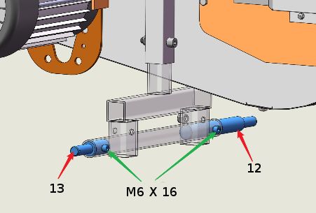
UNDERSTAND YOUR LOG SPLITTER: Read and understand the owner’s manual and labels Symbol on
              affixed to the log splitter. Learn its application and limitations as well as the specific potential the machine
              hazards peculiar to it.
              DRUGS, ALCOHOL AND MEDICATION: Do not operate the log splitter while under the influence
              of drugs, alcohol, or any medication that could affect your ability to use it properly.
              AVOID DANGEROUS CONDITIONS: Use the log splitter on the ground, on the stand supplied
     Safety

              or one of the stands available as accessories. Ensure the stand, if used, is securely assembled.
              Keep your work area clean and well lit. Cluttered areas invite injuries. Do not use the log splitter
Assembly

              in wet or damp areas or expose it to rain. Do not use it in areas where fumes from paint,
              solvents or flammable liquids pose a potential hazard.
              INSPECT YOUR LOG SPLITTER: Check your log splitter before turning it on. Keep guards in
              place and in working order. Form a habit of checking to see that keys and adjusting wrenches
              are removed from tool area before turning it on. Replace damaged, missing or failed parts
              before using it.
              DRESS PROPERLY: Do not wear loose clothing, gloves, neckties or jewellery (rings, wrist
              watches). They can be caught in moving parts.
              Protective electrically non conductive gloves and non-skid footwear are recommended when
              working. Wear protective hair covering to contain long hair, preventing it from getting caught
              in machinery.
              PROTECT YOUR EYES AND FACE: Any log splitter may throw foreign objects into the eyes. This
              can cause permanent eye damage. Always wear safety goggles. Everyday eyeglasses have only
              impact resistant lenses. They are not safety glasses.
              Stand behind and to the right of the machine when operating it. Do not bend over the machine
              to operate it, this is an awkward operating position that has the operator bring their face close
              to the machine, and thus risk being struck by wood chips or debris.

              EXTENSION CORDS: Improper use of extension cords may cause inefficient operation of the
              log splitter which can result in overheating. Be sure the extension cord is no longer than 10m
              and its cross section is no less than 2.5mm2 to allow sufficient current flow to the motor.
              Avoid use of free and inadequately insulated connections. Connections must be made with
              protected material suitable for outdoor use.
              AVOID ELECTRICAL SHOCK: Check that the electric circuit is adequately protected and that it
              corresponds with the power, voltage and frequency of the motor. Check that there is a ground
              connection, and a regulation differential switch upstream.
              Ground the log splitter. Prevent body contact with grounded surfaces: pipes, radiators, ranges,
              and refrigerator enclosures.
              Never open the push button box on the motor without first unplugging the machine from
              the mains. Make sure your fingers do not touch the plug’s metal prongs when plugging or
              unplugging the log splitter.
              AVOID BURNS: Avoid contact with hot oil, exhaust fumes and hot surfaces. Do not touch the
              engine or exhaust, these parts get extremely hot from operation and remain hot for a time after
              the unit is turned off. Allow the engine to cool before doing maintenance or adjustment.

              PETROL ENGINE: DO NOT operate the log splitter in an enclosed area. The exhaust fumes
              contain carbon monoxide an odourless and deadly gas. Operate this unit only in a well ventilated
              area.
              Always stop the engine before moving the machine. Do not alter or adjust any part of the
              machine or engine that is sealed by the manufacturer or distributor. Always check before use,
              as specified in the manufacturers handbook.

   4                                                                        FM6FF & FM8FF (Electric & Petrol
Do not change the engine governor settings or over-speed the engine. The governor controls Symbol on
the maximum safe operating speed of the engine. the machine
Do not run the engine at a high speed when you are not working.
KEEP VISITORS AND CHILDREN AWAY: The log splitter must be always operated by one
person only. Other people should keep a safe distance from the work area, especially when
the log splitter is under operations. Never use another person to help you with freeing
jammed logs.
Safety
INSPECT YOUR LOG: Make sure there are no nails or foreign objects in logs to be split. The
ends of the logs must be cut square. Branches must be cut off flush with the trunk.
DON’T OVERREACH: Floor must not be slippery.
Keep proper footing and balance at all times. Never stand on log splitter. Serious injury could
occur if the tool is tipped or if the cutting tools is unintentionally contacted. Do not store
anything above or near the log splitter where anyone might stand on the tool to reach them.
AVOID INJURY FROM UNEXPECTED ACCIDENT: Always pay full attention to the movement
of the log pusher.
Do not attempt to load the log on until the log pusher has stopped. Keep hands out of the
way of all moving parts.
PROTECT YOUR HANDS: Keep you hands away from splits and cracks which open in the
log; They may close suddenly and crush or amputate your hands.
Do not remove jammed logs with your hands.
DON’T FORCE THE TOOL: It will do a better and safer job at its design rate. Never try to
split logs larger than those indicated in the specifications table. This could be dangerous and
may damage the machine.
Don’t use log splitter for a purpose for which it was not intended.
NEVER LEAVE THE TOOL RUNNING UNATTENDED: Don’t leave tool until it has come to
a complete stop.
DISCONNECT POWER: Unplug the electric motor or remove the plug cap from the spark
plug before making adjustments, changing parts, cleaning, or maintaining the log
splitter. Consult technical manual before servicing.
PROTECT THE ENVIRONMENT: Take used oil to an authorized collection point or follow
the stipulations in the country where the log splitter is used. Do not discharge into drains,
soil or water.
MAINTAIN YOUR LOG SPLITTER WITH CARE: Keep the log splitter clean for best and
safest performance.
MAKE THE WORKSHOP CHILDPROOF: Lock the shop. Disconnect master switches. Store
the log splitter away from children and others not qualified to use it.
NEVER attempt to place a hand or hands in the guard when the log splitter is operation.
NEVER attempt to place logs in the guard or remove them from within the guard when
the log splitter is in operation.
NEVER allow a second person to assist in placing logs in or removing logs from within
the guard whether the log splitter is in operation or not.
FM6FF & FM8FF (Electric & Petrol) 5Before using the log splitter, check all bolts securing the panels of the guard together, the bolts that
secure the cage to the work bench and the bolts that secure the work bench to the log splitter to
ensure they are secure.
DO NOT place fingers or other objects through the holes in the top and angled panels, these holes are
only to allow you to view the log.
Safety
DO NOT attempt to split a log greater than the specified maximum log diameter as this may result in
damage to the guard.
DO NOT attempt to load logs onto the log splitter through the front (fixed blade) opening.
ALWAYS load logs through the right hand rear opening.
DO NOT leave split logs lying inside the guard when splitting a subsequent log as these may be forced
against the cage and damage it.
The warnings, cautions and instructions referred to in this manual cannot cover all possible conditions
and situations that may occur. It must be understood that common sense and caution must be applied
by the operator when using the log splitter.
6 FM6FF & FM8FF (Electric & PetrolAssembly
1
2
8 76 3
54
9 12
10 11 13
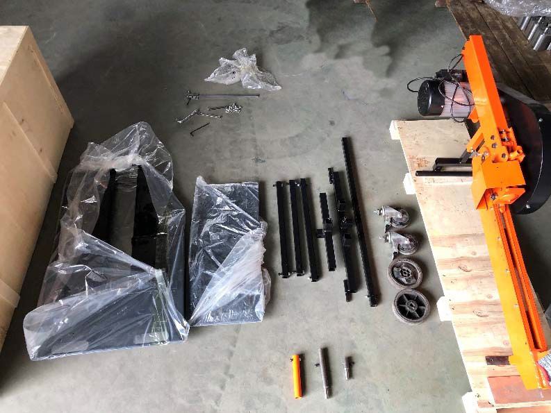
Number Part QTY
1 Log Splitter 1
2 Front Castors 2 14
3 Rear Wheels 2
4 Stand Long Brace 1
5 Stand Rear Axle 1
6 Stand Front Foot 1
7 Stand Front Leg 1
8 Stand Rear Legs 2
9 Safety Cage Sides 6
10 Safety Cage Bench 1
11 Operating Handle 1
12 Long Stub Axle 1
13 Short Stub Axle 1
14 Bench Mounts 4
FM6FF & FM8FF (Electric & Petrol) 7Note that due to the weight of the item, assembly requires two persons
For shipping the rear leg mount is fitted in a reversed position. Before use, remove the bolt securing
this, turn the mount through 180 degrees and secure with the bolt.
Assembly
rear leg mount
reversed correct position
Insert the stub axles, parts 12 and 13 into the tube on the back of the rear leg mount. When looking
from the back of the machine, the short axle part 13 is inserted into the right hand side and the long
axle to the left. Secure the axles with the 2 M6 x 16 cap head bolts and 2 M6 nuts that are fitted in
the axles for shipping.
8 FM6FF & FM8FF (Electric & PetrolAttach the operating lever handle (part 11) to rack engaging
lever on the log spliiter. The bolt and nut for securing the
handle have been fitted to it for shipping.
Assembly
Stand Assembly
As has already been stated, because of the weight of the splitter, it will require two persons to attach
it to the stand
The bolts and nuts necessary to attach all the stand components have been fitted to the components
for shipping.
The easiest way to attach the stand is either on it’s side with the flywheel on the ground or stood
vertically agaisnt a wall with the motor at the bottom. If standing it vertical you must secure it so it
can’t fall over.
Remove the bolts and nuts from the front leg.
Attach the front leg to the mounting socket at the
front of the log splitter and secure with one of the
bolts and nuts just removed.
FM6FF & FM8FF (Electric & Petrol) 9Fasten the castors (part 2) to the front foot (part 6). Use the plate nuts that are fitted to the castors for
shipping. The nut on the plate nut is offset to one end of the plate to make it easier to locate the nut
over the hole in the front foot. Then attach the assembled foot to the bottom of the front leg using the
remaining bolts and nut that were removed from the front leg.
Assembly
Fit the rear legs (part 8) to the rear leg
mount. Note that the bolt holes in the rear
legs are not symetrical top to bottom. One
hole is 15mm from the end the other is
25mm from the end.
Remove the bolt and nut from the hole
that is 15mm from the end and fit this end
into the socket on the rear leg mount then
secure with the bolt and nut.
10 FM6FF & FM8FF (Electric & PetrolRemove the bolts and nuts from the bottom of the rear legs. Attach the Stand Rear Axle (part 5) to the
bottom of the rear legs using the bolts and nuts.
Attach the rear wheels (part 3) to the axles using the split pins provided. These go through the holes in
the end of the axles.
Assembly
Remove the bolt and nut from the Stand Long Brace (part 4) and the bolt from the nut on the locating
tube in the centre of the rear axle.
Insert the Long Brace through the guide tube in the rear axle and into the socket on the rear of the front
castor assembly, so that the holes in the front of the Long Brace line up with the holes in the socket
on the castor assembly. Insert the bolt throught the castor assembly socket and secure with the nut.
Secure the Long Brace to the rear axle guide tube using the bolt. Note there is no hole in the Long Brace
for this bolt, it simply tightens up against the Long Brace.
FM6FF & FM8FF (Electric & Petrol) 11You should now lift the log splitter into the upright position. This must be done by two persons to
avoid the possibility of injury or damage to the log splitter. Check that all nuts and bolts are tight
before lifting the splitter upright.
Assembly
ATTACH THE WORK BENCH AND GUARD
The work bench and guard are only necessary to comply with CE Approval and health and safety at
work legislation in the European Union. Outside of the European Union the individual user can choose
to just use the work bench.
Although the work bench is the best way to support the logs, for customers outside of the EU, a set
of basic log rails can be purchased to be used in place of the work bench. These are available on our
website https://forest-master.com/product/log-guide-rail-for-all-fm8-fm5-log-splitters/.
The work bench & guard package contains
1 x Work Bench (with rear brackets attached)
6 x Guard panels
25 x M6x12 Button Head Bolts (1 spare)
5 x M6x40 Cap Head Bolts (1 spare)
25 x M6 nyloc Nut (1 spare)
5 x M6 Spring Washers (1 spare)
53 x M6 Flat Washers (1 spare)
12 FM6FF & FM8FF (Electric & PetrolAttaching The Work Bench
For shipping, the rear mounting brackets are fastened to the faces to which they attach, in a reversed
position. Before assembly, remove the long mounting bracket (it will be re-attached later) and remove
then reverse the short rear bracket. Note that it must still be fixed to the inner face of the rear side.
Assembly
REMOVE
REVERSE
Attach the work bench to the log rail mounting points using the Bench Mounts (part 14), M6x40 cap
head bolts, M6 spring washers, M6 flat washers. There are 4 mounting points but note that one of the
rear mounting points is for the long rear bracket, which is attached in the next step. Do not fully tighten
the bolts until after the next step. The bench mounts are placed between the body and the mounting
brackets with the tapered end of the mount towards the body.
bench mount
flat washer
spring washer
M6x40 cap head
FM5, FM8 & FM10 (Versions D, T & TW) 13The following steps for fitting the safety guard are only necessary in the EU. Outside of the EU you can
go staright to page 18.
Fit the long rear mounting bracket to the inside face of the long rear edge of the tray and the rear cage
panel to the outside face, using 2 M6x16 cap head bolts, 4 M6 flat washers and 2 M6 nyloc nuts. Then
Assembly
attach the rear bracket to the mounting point on the splitter using an M6x16 cap head bolt, M6 spring
washer and M6 flat washer.
Attach the longer of the two plain cage panels to the left side of the tray and the rear cage panel. The
bottom rear corner has two closely spaced holes,. The top rear corner has a single hole approximately
10mm from the rear edge.
Use 5 M6x12 button head bolts, 10 M6 flat washers (1 under each bolt head and 1 under each nut)
and 5 M6 nyloc nuts.
Do not add a nut
and bolt at this
stage.
M6X12 SOCKET HEAD BOLT
M6 FLAT WASHER
M6 FLAT WASHER
M6 NYLOC NUT
14 FM6FF & FM8FF (Electric & PetrolAttach the shorter of the two plain guard panels to the right side of the work bench. For the orientation
of the panel see the diagram below.
Use 3 M6x12 button head bolts, 6 M6 flat washers (1 under each bolt head and 1 under each nut) and
3 M6 nyloc nuts.
Assembly
TOP
30 30
20 BOTTOM 20
Attach the two flanged panels to the flat top panel, note that the flanges on the angled panels go on
top of the top panel. Use M6x12 button head bolts, M6 flat washers either side and M6 nyloc nuts.
Do not join the longer angled panel to the top panel at it’s rear corner at this stage. This corner is
secured to the back panel in the next step.
Do not bolt this corner
FM6FF & FM8FF (Electric & Petrol) 15BOTTOM TOP
REAR FRONT REAR FRONT
Assembly
TOP BOTTOM
Long Angled Panel
Short Angled Panel
LEFT
REAR
FRONT
RIGHT
Top Panel
Fasten the assembled top section to the side panels and the rear panel using 10 M6x12 button head
bolts, 20 M6 flat washers one either side of the panels for each bolt and an 10 M6 nyloc nut.
Note that the flanges of the angled panels go outside of the plain side panels.
You should now fully tighten all nuts and bolts for the guard and tray.
16 FM6FF & FM8FF (Electric & PetrolNo. Description QTY
1 Rear Guard Panel 1
2 Long Plain Panel 1
3 Long Angled Panel 1
Assembly
6
4 Top Panel 1
5 Short Angled Panel 1
6 Short Plain Panel 1
7 Work Bench 1
8 Short Rear Bracket 1
9 Long Rear Bracket 1
5
10 M6x16 Cap Head Bolts 8
11 M6x12 Button Head Bolt 24
Used for all cage bolts
13
12
12 M6 Flat Washer 60
13 M6 Nyloc Nut 28
11
14 M6 Spring Washer 4
4
7
13
1
14
12
12
8
10
9
3
12
10
1
2
FM6FF & FM8FF (Electric & Petrol) 171 2
Know Your Log Splitter
3
9
8 4
11
5
6
10
7
1 Ram Engaging Lever
2 Safety Guard
3 Wedge
4 Work Bench
5 Hand Holds
6 Stand (TW model only)
7 Locking Castors (minor moving only)
8 Motor / Engine
9 Start Button / Pull Start
10 Wheels (minor moving only)
11 Pusher
18 FM6FF & FM8FF (Electric & PetrolOPERATING CONDITIONS
This log splitter is a home use model. It is designed for operating under ambient temperatures
between +5°C and 40°C and for installation at altitudes no more than 1000m above M.S.L. The
surrounding humidity should be less than 50% at 40°C. It can be stored or transported under
ambient temperatures between -25°C and 55°C.
Operation
ELECTRICAL REQUIREMENTS
Connect the main leads to a standard 230V±10% (50Hz±1Hz) electrical supply which has
protection devices of under-voltage, over-voltage and over-current as well as a residual current
device (RCD) which is maximum residual current rated at 0.03A.
This equipment is fitted with a UK 3 pin mains electricity plug and is supplied with a 2 pin
adapter for use where necessary. DO NOT remove the 3 pin mains electricity plug and fit a 2
pin mains electricity plug.
TWO HANDED CONTROL
This log splitter is equipped with a control system that requires operation by both hands of the user.
One hand controls the lever that engages the ram, while the other hand controls the push button
starter switch (electric) or the throttle control (petrol).
Never move the lever before pressing the button or the throttle.
PETROL ENGINE
The petrol engine is supplied without fuel and oil. Before use, fill the engine with fuel and oil as
specified in the engine manufacturers handbook, included separately.
Start the engine following the procedure given in the engine manufacturers handbook.
POSITIONING THE LOG
Always set logs firmly on the log retaining plates
and work table. Make sure logs will not twist,
rock or slip while being split. Do not force the
blade by splitting the log on the upper part. This
will break the blade or damage the machine.
FM6FF & FM8FF (Electric & Petrol) 19Place the log hard against the splitting wedge. DO NOT place the log against the ram
Operation
Split the log in the direction of its growing grain. Do not place the log across the log splitter for
splitting. It may be dangerous and may seriously damage the machine. Do not attempt to split 2
pieces of log at the same time. One of them may fly up and hit you.
IMPORTANT: Do not place the log against the ram. Do not attempt to split a log across the
grain.
20 FM6FF & FM8FF (Electric & PetrolSPLITTING A LOG ram
engaging
lever
Stand towards the rear of the log splitter, on the
opposite side to the flywheel.
Operation
motor
To split a log with the electric version, press and hold start
the button to start the motor. Once the flywheel has button
spun up, push the ram engaging lever fully forward.
Once the ram hits the log, pull the lever back and
release the motor button and the ram will return.
Note that for soft wood the flywheel does not have to
be spun up to full power.
If the log does not split fully through, DO NOT keep
the power on and the lever engaged. Release them
and have a second go.
To split a log with the petrol version, start the engine then press the trottle trigger to rev the engine
up. Once the flywheel has spun up, push the ram engaging lever fully forward. Once the ram hits
the log, pull the lever back and release the motor button and the ram will return. As with the electric
model, do not hold the throttle and lever on if it does not split fully.
If splitting a log that has already been split,
always place the log so that the split face is
uppermost and the bark covered outer face of
the log is against the bed of the log splitter.
NEVER place a split log with the split face or faces
against the bed of the log splitter, as this can cause
the log to jam against the log guides as it splits,
thereby bending and possibly breaking the log
guides and possibly the body of the log splitter.
WARNING: Never place the split face or faces of a log against the bed of the log splitter.
IMPORTANT: DO NOT hold the power on and lever engaged if the log does not fully split.
FM6FF & FM8FF (Electric & Petrol) 21PETROL ENGINE
For maintenance and trouble shooting of the petrol engine, see the manufacturer’s handbook
included separately.
Maintenance
STORAGE
This machine should be dried before storing and must be stored in an enclosed dry environment. If
it is left in a damp humid environment then water damage may occur to the motor. It should not be
stored under a wood store.
PROBLEM PROBABLE CAUSE REMEDY
Fails to split logs Log is improperly positioned Refer to “Operation” section for correct
log loading.
The sizes or hardness of the log exceeds Reduce the log sizes before splitting it on
the capacity of the machine the log splitter
Electric motor will not Power cord is not plugged in Plug in to power source
start
Fuse or circuit tripped Replace fuse or reset breaker
Damaged power cord Contact Technical Support
Motor hums but does not start, faulty Replace capacitor
capacitor
Ram will not retract or Debris in the rack system Clean / lube rack system periodically
retracts slowly
Return spring is damaged or worn Inspect / replace return spring
Drive belt noise Drive belt is worn Replace drive belt
during start up or
splitting operation
22 FM6FF & FM8FF (Electric & PetrolExploded View FM6FF & FM8FF (Electric & Petrol) 23
No.            Description          QTV.   No.             Description            QTV.
              1    Body                            1    40    Hex. Bolts M8×60                   2
              2    Bushing Φ10                     4    41    Hex. Bolts M6×20                   8
              3    Bushing Φ12                     2    42    Spring Washers Φ6×1.6             10
Parts List

              4    Gear Shaft                      1    43    Hex. Bolts M6×25                   2
              5    Big Washer                      1    44    Hex. Bolts M6×35                   1
              6    Bearings NUP1006                2    45    Lock Nuts M6                      32
              7    Keys                            2    46    Hex. Bolt M8×70                    1
              8    Spring Washers Φ12              3    47    Hex. Bolt M6×70                    1
              9    Reverse thread Bolts M12        1    48    Crossed Discal Screws M4×10        2
             10    Flywheel                        1    49    Spring Wahsers Φ4                  2
             11    Flywheel Cage                   1    50    Flat Washers 4×0.8                 2
             12    Flywheel Back Plate             1    51    Pusher                             1
             13    Screws M6                       6    52    Spring Bracket                     1
             14    Flat Washers Φ6                16    53    Rack                               1
             15    Tension Roller Arm              1    54    Rack Spring                        1
             16    Hex. Bolt M8×60                 1    55    Bearings 6200-2RZ                  8
             17    Bearings 608                    2    56    Bearings 608                       2
             18    Tension Roller                  1    57    Hex. Socket Button Screw M8×40     1
             19    Flat Washers Φ8                 4    58    Flat Washers Φ10                  12
             20    Lock Nuts M8                   8     59    Shoulder Bolt Φ6-M5                1
             21    Tension Roller Bushing         1     60    Flat Washers Φ6                    2
             22    Hex. Socket Button Screw M8×30 1     61    Lock Nut M5                        1
             23    Limit Plate                     1    62    Shoulder Bolt Φ10×45               1
             24    Rubber Bolt M8                  1    63    Lock Nuts M8                       2
             25    Nut M8                          1    64    Shoulder Bolt Φ10×65-M8            1
             26    Beaing Cap                      2    65    Shoulder Bolt Φ10-M8               2
             27    V-Belt                         1     66    Pusher Back Plate                  1
             28    Up Cover                        1    67    Pusher Square Steel                1
             29    Pipe                            1    68    Spring Pins Φ10×50                 2
             30    Pusher Cage                     1    69    Hex. Bolts M10×55                  2
             31    Tray spacer Bushings            4    70    Plate Spacer                       1
             32    Spring Washers Φ8               3    71    Tension Spring                     1
             33    Hex. Bolts M8×20                3    72    Cam Bush                           1
             34    Hex. Bolts M10×20               6    73    Cam Roller                         1
             35    Spring Washers Φ10              6    74    Cam1 V5                            1
             36    Flat Washers Φ10                9    75    CSK Bolt M10                       1
             37    Shoulder Bolt Φ12-M10           1    76    Cam Lever V4                       1
             38    Shoulder Bolt Φ10-M8            2    77    Lever Handle Tube                  1
             39    Lock Thin Nut M10               1    78    Hand Grip                          1

    24                         FM22P Petrol Log SplitterFM6FF & FM8FF (Electric & Petrol
                                                                                      24
No. Description QTV. No. Description QTV.
79 Cam Link Arm 2 118 Cage-04 1
80 CSK M8 1 119 Cage-05 1
Parts List
81 Shoulder Bolt Φ8-M6 1 120 Hex. Socket Button Screw M6 24
82 Socket Head Cap Bolt M6x30 1
83 Cam Spacer 1
84 Flat washers Φ8 2
85 Bracket-A 1
86 Bracket-B 1
87 Bracket-C 1
88 Square Tube-A 1
89 Square Tube-B 2
90 Square Tube-C 1
91 Wheels 2
92 Fixed Plate 2
93 Universal Wheels 2
94 Socket Head Cap Bolt M8×40 8
95 Socket Head Cap Bolt M8×16 1
96 Lock Nuts M8 8
97 Pins Φ2.5×20 2
98 Motor Key 1
99 Motor 1
100 Socket Head Cap Bolt M6×16 3
101 Spring Washers Φ6 4
102 Socket Head Cap Bolt M6×25 1
103 Tension Spring Bracket 1
104 Tension Spring Bracket Spacer 1
105 Belt Wheel 1
106 Hex. Socket Set Screw M6×8 1
107 Tray 1
108 Tray Bracket-VTB-03 1
109 Tray Bracket-VTB-02 1
110 Socket Head Cap Bolt M6×40 4
111 Spring Washer Φ6 4
112 Flat Washers M6 60
113 Socket Head Cap Bolt M6×16 4
114 Cage-06 1
115 Cage-01 1
116 Cage-02 1
117 Cage-03 1
FM6FF & FM8FF (Electric & Petrol)
25 FM22P Petrol Log Splitter 25This product carries a limited parts warranty for 1 year from the date of purchase. Please keep your
proof of purchase as this will be required for any claim.
Should this product become defective, contact the store where it was purchased and either replacement
parts will be issued, it will be repaired or it will be replaced free of charge.
Warranty
IMPORTANT: NO RESPONSIBILITY IS ACCEPTED FOR INCORRECT USE OF THIS PRODUCT.
THIS WARRANTY DOES NOT COVER:
Warranty
1. Any part that has become inoperative due to misuse, abuse, neglect, accident, improper maintenance,
or alteration; or
2. The unit, if it has not been operated and/or maintained in accordance with the owner’s manual; or
3. Normal wear;
4. Routine maintenance items such as lubricants, blade sharpening;
5. Normal deterioration of the exterior finish due to use or exposure.
TRANSPORTATION CHARGES:
Transportation charges for the movement of any power equipment unit or attachment are the
responsibility of the purchaser. The purchaser must pay transportation charges for any part submitted
for replacement under this warranty unless such return is requested by Forest Master.
26 FM6FF & FM8FF (Electric & PetrolFM6FF & FM8FF (Electric & Petrol) 27
NOTE: It is our policy to continually improve products and as such we reserve the right to alter data,
specifications and component parts without prior notice.

Manufactured under license for Forest Master Limited.

Registered Office:
       Forest Master Ltd, Industry Road, Heaton, Newcastle Upon Tyne, NE6 5XB, United Kingdom.
                                         Tel: +44 191 2966939
                      email: info@forest-master.com - web: www.forest-master.com

28                                                            FM6FF & FM8FF (Electric & Petrol
You can also read