Finer SL OPERATING INSTRUCTIONS - TRANSLATION OF THE ORIGINAL OPERATING INSTRUCTIONS READ CAREFULLY PRIOR TO STARTING UP! KEEP OPERATING ...
←
→
Page content transcription
If your browser does not render page correctly, please read the page content below
OPERATING INSTRUCTIONS
                                                                     Finer SL

                                TRANSLATION OF THE ORIGINAL OPERATING INSTRUCTIONS
                                               READ CAREFULLY PRIOR TO STARTING UP!
60056796 • 002 • 07/2021 • en          KEEP OPERATING INSTRUCTIONS IN A SAFE PLACE!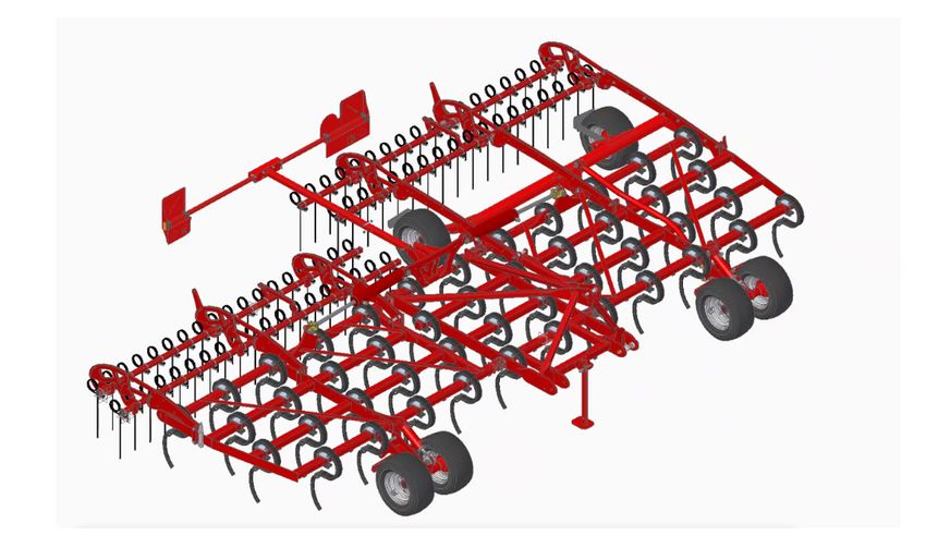
Table of contents

Table of contents
1 Introduction ..........................................................................................................................................                 7
    1.1      Foreword .................................................................................................................................................    7
    1.2      Notes on representation...........................................................................................................................            7
             1.2.1 Warning notes .............................................................................................................................             7
             1.2.2 Instructions ..................................................................................................................................         8

2 Safety and responsibility .......................................................................................................................                       9
    2.1      Intended use ............................................................................................................................................     9
    2.2      Operating Instructions ..............................................................................................................................         9
    2.3      Qualification of personnel ........................................................................................................................ 10
             2.3.1 Groups of operators..................................................................................................................... 10
    2.4      Children in danger.................................................................................................................................... 11
    2.5      Personal protective outfit ......................................................................................................................... 11
    2.6      Safety in traffic ......................................................................................................................................... 11
    2.7      Safety in operation ...................................................................................................................................      12
             2.7.1 Commissioning ............................................................................................................................             12
             2.7.2 Damage to the machine...............................................................................................................                   12
             2.7.3 Hitching and uncoupling ..............................................................................................................                 13
             2.7.4 Hydraulics ....................................................................................................................................        13
             2.7.5 Overhead lines .............................................................................................................................           14
             2.7.6 Technical limiting values...............................................................................................................               14
             2.7.7 Use in the field.............................................................................................................................          15
             2.7.8 Changing equipment / wear items ...............................................................................................                        15
             2.7.9 Fertiliser and dressed seed ...........................................................................................................                16
             2.7.10 Environmental protection.............................................................................................................                 16
             2.7.11 Retrofitting and conversions ........................................................................................................                 16
             2.7.12 Spare parts ..................................................................................................................................        16
             2.7.13 Care and maintenance .................................................................................................................                17
    2.8      Danger zone............................................................................................................................................. 18
    2.9      Safety stickers .......................................................................................................................................... 18
             2.9.1 Positions of safety stickers............................................................................................................ 20

3 Commissioning...................................................................................................................................... 21
    3.1      Delivery .................................................................................................................................................... 21
    3.2      Transport ................................................................................................................................................. 21
    3.3      Installation ............................................................................................................................................... 22

4 Technical data....................................................................................................................................... 23
    4.1      Technical data .......................................................................................................................................... 23
    4.2      Type plate ................................................................................................................................................ 25
    4.3      Requirements on the tractor..................................................................................................................... 26
             4.3.1 Calculating the ballasting ............................................................................................................. 27

60056796 • 002 • 07/2021 • en                                                                                                                                              3
Table of contents

5 Attachment........................................................................................................................................... 30
    5.1      Overview.................................................................................................................................................. 30
    5.2      Hydraulics ................................................................................................................................................ 30
             5.2.1 Marking of hydraulic hoses .......................................................................................................... 31
    5.3      Aluminium clips........................................................................................................................................ 32
    5.4      Lighting.................................................................................................................................................... 33
    5.5      Instruction stickers ................................................................................................................................... 34

6 Assembly groups................................................................................................................................... 35
    6.1      Spring-loaded tines .................................................................................................................................. 35
    6.2      Harrow..................................................................................................................................................... 36

7 Operation.............................................................................................................................................. 37
    7.1      Connecting / Parking ................................................................................................................................        37
             7.1.1 Connecting ..................................................................................................................................          37
             7.1.2 Transport position........................................................................................................................             38
             7.1.3 Parking ........................................................................................................................................       39
    7.2      Folding..................................................................................................................................................... 40
             7.2.1 Unfolding..................................................................................................................................... 41
             7.2.2 Folding in..................................................................................................................................... 41
    7.3      Depth setting ........................................................................................................................................... 41
    7.4      Use in the field .........................................................................................................................................   43
             7.4.1 Work instructions.........................................................................................................................             43
             7.4.2 Headland .....................................................................................................................................         43
             7.4.3 Checks .........................................................................................................................................       43
                     Position of control units during use in the field ............................................................................                       44

8 Care and maintenance .......................................................................................................................... 45
    8.1      Maintenance overview .............................................................................................................................           45
             8.1.1 After 10 operating hours .............................................................................................................                 45
             8.1.2 Before the season ........................................................................................................................             46
             8.1.3 During the season........................................................................................................................              46
             8.1.4 At the end of the season..............................................................................................................                 47
    8.2      Lubricating the machine ........................................................................................................................... 48
    8.3      Clean the machine.................................................................................................................................... 49
    8.4      Machine storage ...................................................................................................................................... 49

9 Disposal ................................................................................................................................................ 50
    9.1      Decommissioning ..................................................................................................................................... 50

10 Appendix .............................................................................................................................................. 51
    10.1 Tightening torque.....................................................................................................................................           51
         10.1.1 Metric screws (Nm) ......................................................................................................................                 51
         10.1.2 Metric screws (ft.lb) .....................................................................................................................               52
         10.1.3 Inch screws (Nm) .........................................................................................................................                53
         10.1.4 Inch screws in (ft lb) .....................................................................................................................              54

4                                                                                                                                60056796 • 002 • 07/2021 • en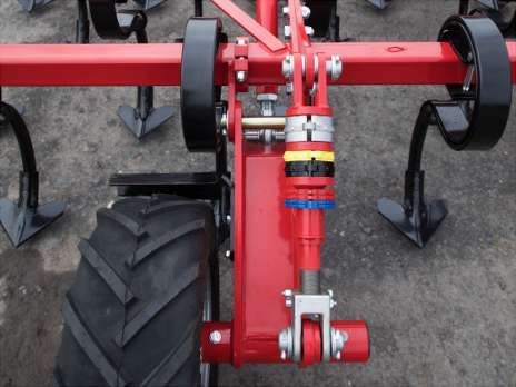
EG-Konformitätserklärung
                                 Die HORSCH Maschinen GmbH, Sitzenhof 1, D-92421 Schwandorf, erklärt hiermit in
                                 alleiniger Verantwortung als Hersteller, dass das nachfolgend genannte Produkt:
                                 Grubber
                            Typ: Finer 6 SL, Finer 7 SL
                                 den einschlägigen grundlegenden Sicherheits- und Gesundheitsanforderungen der
                                 Richtlinie 2006/42/EG entspricht.

                                  Schwandorf, 07.05.2021                  Klaus Winkler
                                                                          Dokumentationsbevollmächtigter

                                  Philipp Horsch                          Hubertus Bultmann
                                  Geschäftsführer                         Leiter Forschung & Entwicklung

                                 Translation of EC Declaration of Conformity
                                 HORSCH Maschinen GmbH, Sitzenhof 1, D-92421 Schwandorf, Germany, hereby de-
                                 clares in its sole responsibility as manufacturer that the following product:
                                 Cultivator
                           Type: Finer 6 SL, Finer 7 SL
                                 conforms with the relevant fundamental health and safety requirements of the EC
                                 directive 2006/42/EC.

                                 Schwandorf, 07/05/2021                   Klaus Winkler
                                                                          Documentation Representative

                                 Philipp Horsch                           Hubertus Bultmann
                                 Managing director                        Director Research & Development

60056796 • 002 • 07/2021 • en                                                                                      5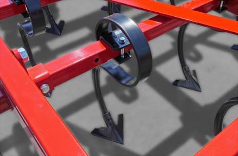
Identification of machine
                 Please enter the corresponding data into the following list upon reception of the
                 machine:
                 Serial number:
                 Machine type:
                 Year of construction:
                 Initial use:
                 Accessories:

Dealer address   Name:
                 Road:
                 Place:
                 Phone:
                 Cust. No. Dealer:
                 Cust. No. HORSCH

6                                                                       60056796 • 002 • 07/2021 • en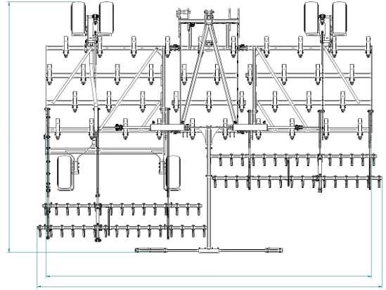
1 Introduction
                         1.1 Foreword
                                Before commissioning the machine, read and strictly comply with the operating in-
                                structions. This will avoid dangers, reduce repair costs and downtimes and increase
                                the reliability and service life of your machine.
                                The operating instructions facilitate getting to know the machine and its utilisation
                                in the framework of the intended use options.
                                Observe the safety notes!
                                HORSCH will not assume liability for any damage or malfunctions resulting from fail-
                                ure of complying with the operating instructions.
                                Any person commissioned to performing tasks on or with the machine must read
                                and apply the operating instructions.
                                These tasks include:
                                 • Operation of the machine, including preparation, fault rectification during work
                                   and care.
                                 • Preventive and regular maintenance and inspection.
                                 • Transport
                                Trained personnel of our service and sales partners will provide orientation on how
                                to operate and maintain the machine.
                                By submitting the acknowledgement of receipt proper acceptance of the machine is
                                considered confirmed. The warranty period starts with the date of delivery.
                                We reserve the right to alter illustrations as well as technical data and weights con-
                                tained in these operating instructions for the purpose of improving the machine.
                                The illustrations in these operating instructions show different versions of the ma-
                                chine and different equipment variants.

                         1.2 Notes on representation

                       1.2.1 Warning notes
                                These operating instructions distinguish between three different types of warning
                                notes.
                                The following signal words with warning symbols are used:

                                 DANGER
                                Highlights a danger that will lead to death or severe injury if it is not avoided.

                                 WARNING
                                Highlights a danger that may lead to death or severe injury if not avoided.

60056796 • 002 • 07/2021 • en                                                                                            7
1 | Introduction

                          CAUTION
                         Highlights a danger that can lead to injury if not avoided.

                         Read all warning notes in these operating instructions!

                   1.2.2 Instructions

                          NOTE
                         Identifies important notes.

                         Instructions for actions and their elements are marked by different symbols:
                           ü Prerequisites for instructions for actions.
                            1. Instructions for actions (alternative and in warning notes: arrow tips)
                              ð Intermediate results of instructions for action.
                           ð Final results of instructions for action.
                            2. Keep the order of the instructions.
                         The designations right, left, front and rear apply as seen in travel direction.

8                                                                                  60056796 • 002 • 07/2021 • en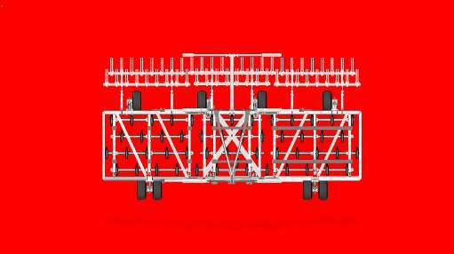
2 Safety and responsibility
                                The following warnings and safety notes apply to all sections in these operating in-
                                structions.
                                The machine has been built in accordance with latest technical standards and gener-
                                ally accepted safety regulations. However, risks for life and limb of the operator or
                                third parties and impairment of the machine or other material assets can occur dur-
                                ing use.

                                  Ø Observe the following safety notes before using the machine.

                         2.1 Intended use
                                The machine is intended for the flat tillage of agricultural areas.
                                The intended use also includes taking note of and observing the notes and instruc-
                                tions given in these operating instructions, observing all pictograms and warnings
                                on the machine, observing all maintenance and repair intervals and complying with
                                the defined technical limits and areas of application.

                                When participating with the machine in public road traffic, the respective national
                                registration and traffic law must also be complied with.

                                Any other kind of use of the machine contradicting the above, is considered not as
                                intended, especially:
                                 • connecting/attachment to an agricultural tractor that is not suitable
                                 • using the machine to loosen and tear up roads, lanes and other paved sub-
                                   strates
                                 • loosening extremely compacted field areas (can be recognised by the constant
                                   jumping up of the tines when traversed or by the repeated shearing off of the
                                   tines with shear bolt protection)
                                 • deliberate detachment and/or pulling out of stone slaps or boulders during till-
                                   age of an agricultural area
                                 • operating the machine while persons are still in the danger zone (this includes in
                                   particular transport rides on the machine)
                                 • carrying out maintenance and/or repair work on a machine that has not been
                                   shut down or is not secured against restarting
                                HORSCH does not assume any liability for damages resulting from the unintended
                                use of the machine.

                         2.2 Operating Instructions
                                The operating instructions are a part of the machine!
                                Failure to comply with the operating instructions can result in severe or even fatal
                                physical injuries.
                                  Ø Read and follow the corresponding sections in the operating instructions be-
                                    fore starting work.
                                  Ø Store the operating instructions and keep for future use.
                                  Ø Pass the operating instructions on to a later user.

60056796 • 002 • 07/2021 • en                                                                                          9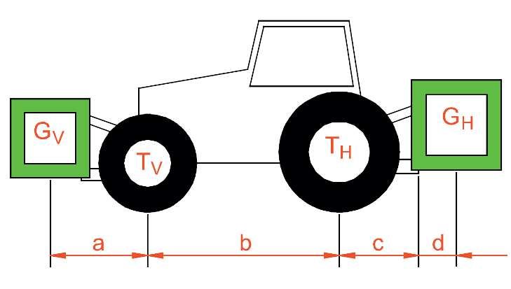
2 | Safety and responsibility

                                2.3 Qualification of personnel
                                    Unintended use of the machine can lead to severe or even fatal physical injuries. In
                                    order to prevent accidents, each person involved in work with the machine must
                                    meet the following general minimum requirements:

                                      Ø The person must be physically able to keep the machine under control.
                                      Ø The person is able to perform work with the machine safely within the scope
                                        of these operating instructions.
                                      Ø The person is acquainted with the function of the machine within the scope of
                                        its work and is able to assess and avoid any work related dangers. The person
                                        is able to recognize and avoid work-related dangers.
                                      Ø The person has understood the operating instructions and is able to implement
                                        the information given in the operating instructions accordingly.
                                      Ø The person is fully familiar with the safe operation of the vehicle.
                                      Ø The person knows all applicable road traffic regulations and is in possession of
                                        a valid driving permit for road travel.
                                      Ø A person being instructed must only work with or on the machine under the
                                        supervision of an experienced person.

                                    The owner of the machine must
                                     • Regulate the area of responsibility, competence and monitoring of personnel.
                                     • Train and instruct the personnel.
                                     • Make the operating instructions accessible for the operator.
                                     • Ensure that the operator has read and understood the operating instructions.

                            2.3.1 Groups of operators
                                    Persons who work with the machine must have been trained for the different activit-
                                    ies involved.

Instructed operators                These persons must have been trained for their respective activities by the owner or
                                    other qualified experts.
                                    This refers to the following activities:
                                     • Road transportation
                                     • Application and set-up work
                                     • Operation
                                     • Maintenance
                                     • Troubleshooting and repair

Operator trained by                 Furthermore, for certain activities the corresponding personnel must have been
HORSCH                              trained by service personnel from HORSCH.
                                    This refers to the following activities:
                                     • Loading and transport
                                     • Commissioning
                                     • Troubleshooting and repair

10                                                                                          60056796 • 002 • 07/2021 • en
Safety and responsibility | 2
• Disposal
Certain work concerning maintenance and repair must only be carried out by an ex-
pert workshop. Such work is identified with the additional comment Workshop
work.
2.4 Children in danger
Children are not able to assess dangers and may behave unpredictably. Children are
therefore especially endangered.
Ø Keep children away from the machine
Ø Especially before driving off and before triggering machine movements you
must make sure that the danger zone is free of children.
Ø Shut down the tractor before leaving it. Children can trigger dangerous ma-
chine movements. An insufficiently secured machine parked without being at-
tended poses a danger for playing children.
2.5 Personal protective outfit
Missing or incomplete protective equipment increases the risk of health damage.
Personal protective equipment includes, e.g.:
• Tight fitting clothes / protective clothing, possibly a hair net
• Safety shoes
• Safety gloves
• Safety goggles to protect the eyes against dust or spray, when working with fer-
tiliser or liquid fertiliser. Observe the regulations given by the fertiliser manufac-
turer!
Ø Respirator masks and protective gloves when handling dressing or dressed
seed. Observe the safety data sheets of the dressing manufacturer!
Ø Determine the personal protective equipment for the corresponding work as-
signment.
Ø Provide effective protective equipment in proper condition.
Ø Never wear rings, bracelets or other jewellery.
2.6 Safety in traffic
DANGER
No passengers are allowed to ride on the machine!
Ø Pay attention to permissible transport widths and heights. Pay attention to the
transport height when passing under bridges and low hanging overhead
power lines.
Ø Do not exceed the permissible axle load, tyre load bearing capacity and total
weight, in order to ensure sufficient steering and braking capabilities.
The weight of the tractor must at least be equivalent to the curb weight of the
machine.
The front axle must be loaded with at least 20 % of the tractor weight.
60056796 • 002 • 07/2021 • en 112 | Safety and responsibility
Ø For machines without brake select the weight of the tractor and the speed so
that the machine can be managed securely under all conditions. Remember
the extended breaking distance.
For road transport the machine must be set to transport position. The machine must
have been folded up and secured, see chapter Folding in and Connecting and Trans-
port position.
Ø Clean soil from the folding areas before folding in. Otherwise there could be
damage to the mechanics.
Ø Secure the hydraulic cylinders, if so equipped on undercarriage and drawbar in
transport position against uncontrolled movements using aluminium clips, see
chapter Connecting and Transport Position.
Ø Assemble lighting, warning and protective features and check the function.
Ø Before road travel clean the entire machine from picked up dirt.
Ø Handling is affected by the connected equipment. Pay particular attention to
the wide overhang and the centrifugal mass of the working implement when
cornering.
Ø Raised machines (3-point hydraulics): Consider the limited stability and steering
capability of the tractor.
Ø When transporting along public roads pay attention to the permissible top
speed specified in the type approval.
Ø The specifications in the type approval document or in the technical data are
decisive for the design dependent top speed.
Ø Always match the travel mode to the road conditions to avoid accidents and
damage to the undercarriage.
Ø Consider your personal abilities, carriage way, traffic, sight and weather condi-
tions.
2.7 Safety in operation
2.7.1 Commissioning
The operational safety of the machine cannot be guaranteed without orderly per-
formed commissioning. This can lead to accidents with severe or even fatal physical
injuries.
Ø The machine must only be put into operation after receiving instructions by
employees of the authorized dealer or a HORSCH employee.
All protective features and safety equipment, such as detachable protective devices
(wheel chocks, etc.), must be correctly in place and reliably functioning before the
machine is put into operation.
Ø Check nuts and bolts, especially the ones on wheels and cultivation tools regu-
larly for tight fit and retighten if necessary.
Ø Check the tyre pressure at regular intervals, see maintenance overview.
2.7.2 Damage to the machine
Damage to the machine can impair the operational safety of the machine and cause
accidents. This can lead to severe or even fatal physical injuries.
The following machine parts are particularly important for safety:
• Hydraulics
• Brakes (if available)
12 60056796 • 002 • 07/2021 • enSafety and responsibility | 2
• Connecting features
• Protective features
• Lighting
If in doubt about the safety-relevant status of the machine, e.g. in case of leaking
operating fluids, visible damage or unexpected changes in driving behaviour:
Ø Immediately shut down and secure the machine.
Ø If possible, locate and rectify the faults by following these operating instruc-
tions.
Ø Rectify possible causes for damage (e.g. remove coarse dirt and tighten loose
screws).
Ø Have damage that could affect safety and that cannot be rectified by you recti-
fied by a qualified expert workshop.
2.7.3 Hitching and uncoupling
Faulty coupling of the machine to the pulling tool of the tractor causes dangers,
which could result in severe accidents.
Ø Strictly comply with all operating instructions:
• These operating instructions
• Operating instructions of the tractor
Ø Exercise special caution when reversing the tractor. Never stand between
tractor and machine.
Ø Only park the machine on a firm and level surface. Before unhitching the
towed machine, lower it to the ground.
Ø Secure the machine against rolling away.
2.7.4 Hydraulics
The hydraulic system is under high pressure.
The machine's hydraulics has several functions, which can cause injury to persons or
damage to the machine if operated incorrectly:
• Escaping fluid may penetrate the skin.
• Hydraulically supported machine parts may drop.
• Hydraulic components may be flung away. Pressurised hydraulic hoses may whip
about when detaching them.
Ø Connect the hydraulic hoses to the tractor only when the hydraulics on tractor
and machine are depressurised.
Ø Lower all hydraulically lifted parts (e.g. wings, packer, undercarriage, etc.) to
the ground before performing any work on the hydraulic system. Depressurise
the hydraulics on the tractor and implement side.
Ø The hydraulic system is under high pressure. Check all lines, hoses and screwed
connections regularly for leaks and any visible external damage!
Ø Use only appropriate means when searching for leaks. Repair any damage im-
mediately! Oil sprays can cause burns and fire!
Ø Power sockets and connectors on the hydraulic connections should be marked
in order to exclude operating errors.
Ø In the event of injury, consult a doctor immediately.
Ø Secure and lock the control unit on the tractor if not in use!
Ø Replace hydraulic hoses at the latest after six years, see Maintenance overview.
60056796 • 002 • 07/2021 • en 132 | Safety and responsibility
Ø To prevent unintentional machine movements due to air trapped in the hy-
draulic cylinders these cylinders must already be filled with hydraulic oil before
installing them in the machine. The cylinder and hose assembly are then bled
by retracting and extending the cylinder several times.
The hydraulic system is equipped with pressure accumulators.
The regulations applying at the location of use during operation must be observed
to this end. The owner is solely responsible for complying with them.
Ø Do not open or work (welding, soldering, drilling) on pressure accumulators.
Even when empty, the tanks are still preloaded by gas pressure.
Ø Maintenance and repair work on the pressure accumulator must only be car-
ried out by trained and qualified personnel.
2.7.5 Overhead lines
When unfolding or folding in the wings, the machine may reach the height of over-
head lines. Possible voltage flashover to the machine may cause fatal electric shock
or fire.
Ø Keep a safe distance to electric high voltage power lines with the wings folded
and when unfolding or folding in the wings.
Ø Do not unfold or fold in the wings in the vicinity of pylons and power lines.
Ø Never leave or access the machine under overhead lines to avoid possible risks
of electric shock or voltage flashover.
What to do in case of Voltage flashover generates high electric voltages on the outside of the machine.
voltage flashover This results in extreme voltage differences at the ground around the machine. Wide
strides, laying on the ground or supporting yourself with your hands on the ground
can cause life-threatening electric currents (pace voltage).
1. Do not leave the cabin.
2. Do not touch any metal objects.
3. Do not create a conductive connection to ground.
4. Warn persons: DO NOT come near the machine. Electric voltages at the
ground can cause severe electric shock.
5. Wait for professional rescuers. The overhead power line needs to be switched
off.
If persons need to leave the cabin despite the voltage flashover, e.g. in case of a po-
tential life-threatening risk of fire:
6. Jump away from the machine. Ensure a safe stand when jumping. Do not
touch the outside of the machine.
7. Move away from the machine with short stepping strides.
2.7.6 Technical limiting values
If the technical limiting values of the machine are not observed, the machine may
get damaged. This can lead to accidents with severe or even fatal physical injuries.
The following technical limiting values are of particular importance for safety:
• Permissible total weight
• Maximum axle loads
• Maximum drawbar load
• Maximum speed
14 60056796 • 002 • 07/2021 • enSafety and responsibility | 2
See chapter Technical data, Type plate and Type approval.
Ø Also pay attention to the maximum loads for the tractor.
2.7.7 Use in the field
DANGER
No passengers are allowed to ride on the machine!
Ø Operate the machine only in reliable weather conditions.
Ø Check the area immediately around the machine (for children!) before driving
off and commissioning the machine. Ensure sufficient visibility.
Ø Check the condition of the cultivation tools and their mounting before use.
Ø Driving stability may be affected in the following situations, especially when
cornering: Driving at accelerated speed, along the contour line toward the
slope and on uneven terrain with longitudinal and lateral incline. Ensure suffi-
cient stability of the machine. Pay attention to the limiting values for the
tractor.
Ø Driving stability may be affected when using auxiliary equipment or, if permit-
ted, driving with filled seed hopper. Ensure sufficient stability of the machine.
Pay attention to the limiting values for the tractor.
Ø Do not remove any of the prescribed and supplied protective devices.
Ø Stay clear of the operating range of hydraulically operated parts.
Ø Do not drive backwards with the machine lowered. The components have only
been designed for forward travel in the field and may be damaged when re-
versing.
2.7.8 Changing equipment / wear items
Ø Only pulling tools may be attached that meet the technical requirements ac-
cording to these operating instructions. HORSCH does not assume any liability
for damages resulting from the attachment of non-fitting pulling tools as well
as incorrect mounting.
Ø For machines with valid type approval only pulling tools may be attached that
are covered by the type approval. Attaching pulling tools not covered by the
type approval will void the registration.
Ø Secure the machine against unintended rolling away!
Ø Secure raised frame parts under which persons will be present with suitable
supports!
Ø Caution! Danger of injury caused by projecting parts (e.g. coulters)!
Ø Assume ergonomic working postures with any assembly work.
Ø Do not step on rotating parts when climbing onto the machine. They may spin
and create the danger of very serious injuries from falling.
60056796 • 002 • 07/2021 • en 152 | Safety and responsibility
2.7.9 Fertiliser and dressed seed
Inappropriate handling of fertiliser and dressed seed can cause poisoning and death.
Ø Follow the information given in the safety data sheet of the manufacturer. If
necessary, ask the dealer for the safety data sheet or safety notes.
Ø Determine and provide the personal protective outfit as specified by the manu-
facturer.
2.7.10 Environmental protection
Operating materials such as hydraulic oil, lubricants, etc. can damage the environ-
ment and the health of persons.
Ø Do not allow operating materials to drain out into the environment.
Ø Pick up drained operating materials with absorbent material or sand, fill it into
a leak tight tank and dispose of in accordance with statutory regulations.
2.7.11 Retrofitting and conversions
Structural changes not approved by HORSCH may affect the functionality and opera-
tional safety of the machine and will void any warranty claim.
HORSCH is not liable for damages to life and limb as well as property damages res-
ulting from unapproved retrofitting and conversions.
Ø Do not perform any structural changes to the pulling tool of the machine.
Ø Do not make any structural changes or extensions that have not been ap-
proved by HORSCH.
Ø Modifications and extensions approved by HORSCH are only to be performed
at an authorized workshop or by an operator who has been trained by
HORSCH for this purpose.
Ø Comply with country-specific regulations for weights, weight distribution and
dimensions.
For equipment affecting the weight or weight distribution the regulations concern-
ing towing facility, support and axle load must be checked and complied with. For
machines without brakes a brake system may need to be retrofitted if the permiss-
ible weight limits are exceeded.
In case of changes concerning data mentioned on the type plate, a new type plate
with updated data must be attached.
In case of changes which concern the data in the type approval, this type approval
needs to be renewed.
2.7.12 Spare parts
Genuine spare parts and accessories from HORSCH have been specially designed for
this machine.
Spare parts and accessories which are not delivered by us have not been tested or
approved by us.
The installation or use of other than HORSCH products can therefore negatively af-
fect the design characteristics of the machine and thus impair the safety of man and
machine.
HORSCH will not assume liability whatsoever for damage resulting from the use of
non-original parts and accessories.
If the component to be replaced is marked with a safety sticker, these stickers must
also be ordered and attached to the spare part.
16 60056796 • 002 • 07/2021 • enSafety and responsibility | 2
2.7.13 Care and maintenance
Inappropriate care and maintenance put the operational safety of the machine at
risk. This can lead to accidents with severe or even fatal physical injuries.
Ø Conform to prescribed schedules for repetitive tests or inspections.
Ø Service the machine according to the maintenance plan, see chapter Care and
maintenance.
Ø Only perform the work described in these operating instructions.
Ø Before starting maintenance and service work park the machine on level and
firm ground and secure it against rolling away.
Ø Depressurise the hydraulic system and lower or support the implement.
Ø Prior to working on the electrical system, disconnect it from the electric cur-
rent supply.
Ø When performing welding work on the machine, disconnect the cables from
electronic components. The ground connection must be as close as possible to
the welding point.
Ø Before cleaning the machine with high pressure cleaner cover all openings,
which should stay clear of water, steam or cleaning agents for reasons of
safety or operation. Do not aim the water jet directly on electric or electronic
components or bearings. When cleaning with high-pressure cleaning equip-
ment or steam jet always keep a distance of at least 50 cm to machine com-
ponents.
Ø After cleaning, check all hydraulic lines for leaks and loose connections.
Ø Check for chafing and signs of damage. Remedy any faults immediately!
Ø Retighten screw connections loosened for care and maintenance work.
Ø Do not clean new machines with a steam jet of a high pressure cleaner. The
paint takes approx. 3 months to cure and could be damaged before this time.
Ø Danger of explosion! Do not exceed the specified tire pressure, see Mainten-
ance overview.
NOTE
All other maintenance and repair tasks, which are not described in the operating in-
structions, must only be carried out by an authorized professional workshop or by
an operator who has been trained by HORSCH for this purpose.
60056796 • 002 • 07/2021 • en 172 | Safety and responsibility
2.8 Danger zone
The area indicates the danger zone of the machine:
The danger zone around the machine poses the following hazards:
• Accidental operation of the hydraulics can trigger dangerous movements of the
machine.
• With the drive still running, machine parts may rotate or swing out.
• Hydraulically raised machine parts can lower slowly and unnoticed.
Failing to pay attention to the danger zone can result in severe or even fatal physical
injuries.
1. Do not stand under lifted loads. Lower such loads to the ground first.
2. Instruct persons to leave the danger zone around the machine and tractor be-
fore any machine movements.
3. Before working in the danger zone of the machine or between machine and
tractor: Shut down the tractor!
This also applies to temporary inspection work.
Many accidents happen because of carelessness and running machines!
4. Pay attention to the information in all operating instructions.
2.9 Safety stickers
Safety stickers on the machine warn of hazards at dangerous points and are an im-
portant part of the safety equipment of the machine. Missing safety stickers increase
the risk of severe or even fatal injuries.
1. Clean soiled safety stickers.
2. Damaged or illegible safety stickers must be replaced immediately.
3. Affix the specified safety stickers on spare parts.
No passengers are allowed to ride on the machine!
00380054
18 60056796 • 002 • 07/2021 • enSafety and responsibility | 2
Before commissioning the machine the operating instruc-
tions must be read and followed!
00380055
Caution for fluids spraying out under high pressure, follow
the notes in the operating instructions!
00380133
Never reach into areas where there is a risk of crushing as
long as parts could still be moving!
00380134
Stay clear of the operating range of foldable machine
parts!
00380135
When connecting the machine and when operating the hy-
draulics, no persons are allowed between the machines!
00380145
Shut the engine down and pull off the key before starting
maintenance and repair work.
00380294
60056796 • 002 • 07/2021 • en 192 | Safety and responsibility
Do not climb on rotatable parts. Use mounting steps
provided for this purpose.
00380299
2.9.1 Positions of2xsafety stickers
The positions of the safety stickers depend on the equipment.
Safety stickers with the addition "2x" can be found on either side of the machine.
2x
20 60056796 • 002 • 07/2021 • en3 Commissioning
NOTE
These work activities may be carried out only by persons trained by HORSCH for this
purpose.
WARNING
Increased danger of accidents during commissioning.
Ø Observe the notes in the Safety chapter and familiarise yourself with the ma-
chine!
3.1 Delivery
The machine with implements is normally delivered completely assembled on a low
loader.
If parts or assembly groups had to be disassembled for transport purposes, these
will be assembled locally by the sales partner or field technician.
Depending on the design of the low loader the machine can be unloaded with a
tractor or needs to be lifted off with suitable lifting gear (forklift truck or crane).
Ø Use only lifting equipment and lifting gear with adequate lifting capacity and
approval!
Ø Points with the associated stickers "Strapping point" must not be used for
load suspension!
When using other lifting points pay careful attention to the centre of gravity and the
weight distribution. These points must, in any case, only be on the frame of the ma-
chine.
3.2 Transport
Depending on country specific regulations and working width the equipment can be
transported on public roads, either attached to a tractor or on a trailer or low
loader.
1. The permissible dimensions and weights for transport must be complied with.
2. Choose the tractor large enough, to ensure sufficient steering and braking
capabilities.
3. On machine with tractor link arm or three-point connection: block the tractor
link arms against swinging sideways.
4. Secure the machine on a trailer or low loader with suitable securing means
(e.g. Load straps or chains).
5. Attach lifting tackle only at the marked points.
60056796 • 002 • 07/2021 • en 213 | Commissioning
3.3 Installation
Instruction of the operator and initial installation of the machine will be carried out
by our service engineers or distributors.
Any preceding use of the machine is prohibited!
The machine can only be released for operation after the instruction session conduc-
ted by service technicians or sales partners and after the operating instructions have
been read.
WARNING
Increased danger of accidents during commissioning.
Ø Observe the notes in the Safety chapter and familiarise yourself with the ma-
chine!
1. Take loosely delivered parts off the machine.
2. Check all important screw connections.
3. Lubricate all lubrication points.
4. Check the air pressure in all tyres and correct it if necessary.
5. Check all hydraulic connections and hoses for correct fastening and function.
6. Immediately rectify any occurring damage or have it corrected.
22 60056796 • 002 • 07/2021 • en4 Technical data
4.1 Technical data
Finer 6 SL 7 SL
Working width 6.00 m [19' 8"] 7.00 m [23']
Transport width 2.55 m [8' 4"] 2.55 m [8' 4"]
Transport height 3.10 m [10' 2"] 3.60 m [11' 10"]
Length 2.40-3.80 m [7'10"-12'6"] 2.40-3.80 m [7'10"-12'6"]
(depending on the equip- (depending on the equip-
ment) ment)
Weight * 1,850-3,400 kg 2,000-3,700 kg
[4.080-7.500 lbs ] (depend- [4.410-8.160 lbs ] (depend-
ing on the equipment) ing on the equipment)
Number of tines 39 45
Tine spacing in one row 62 cm [2'] 62 cm [2']
Groove spacing 15.4 cm [6.06"] 15.6 cm [6.14"]
Tyre size of depth guide 23x10.5-12 23x10.5-12
wheels
Frame height 58.5 cm [1' 11.0"] 58.5 cm [1' 11.0"]
Working depth max. 10 cm [3.94"] 10 cm [3.94"]
60056796 • 002 • 07/2021 • en 234 | Technical data
Finer 6 SL
4590
5960
6310
3260
3060
2520
2700
24 60056796 • 002 • 07/2021 • enTechnical data | 4
Finer 7 SL
6960
4590
7290
3730
2700
4.2 Type plate
The type plate with the CE marking is located on the frame or the hopper of the ma-
chine.
Data on the type plate:
Made in Germany
Maschinen GmbH
Sitzenhof 1, D-92421 Schwandorf Tel.: +49 9431 7143-0
www.horsch.com
SN m kg
1 2 3 4
1 Model designation
2 Serial number
3 Year of construction
4 Weight
60056796 • 002 • 07/2021 • en 254 | Technical data
Information on year of manufacture
• Year of manufacture in VIN/Vehicle Identification Number (coded):
Embossed when basic vehicle or undercarriage is manufactured
• Year of manufacture on the type plate:
Time of final production of the machine in the respective equipment version
Due to processes, there may be some periods between the manufacturing of the ba-
sic vehicle and final production. There may be differences therefore with the spe-
cification of the year of manufacture.
4.3 Requirements on the tractor
WARNING
Risk of accident from overloading the tractor.
Ø Observe the permissible values of the tractor for axle loads, total weight, tyre
load bearing capacity and air pressure.
Ø Verify the suitability of the tractor before commissioning.
The tractor must meet the following requirements to be able to use the machine as
intended:
Implement attachment Finer 6 SL 7 SL
Three-point Cat. III/IV Cat. III/IV
*Tractor link arm implement attachment:
III: Coupling point distances Cat. III Pin diameter Cat. III
IV: Coupling point distances Cat. IV Pin diameter Cat. IV
II/III: Coupling point distances Cat. II Pin diameter Cat. III
III/IV: Coupling point distances Cat. III Pin diameter Cat. IV
Hydraulics Number of dual-acting control units 1 (+1 per option)
Oil grade Mineral hydraulic oil
Oil purity acc. to ISO 4406: 18/16/13
Maximum system pressure 210 bar [3.045 psi]
Engine power Finer 6 SL 7 SL
min. (kW / HP) 115/160 130/180
max. (kW / HP) 200/270 220/300
26 60056796 • 002 • 07/2021 • enTechnical data | 4
4.3.1 Calculating the ballasting
The permissible total weight, the permissible axle loads and the tyre load bearing ca-
pacity must not be exceeded when mounting or connecting implements.
The front axle of the tractor must always be loaded with at least 20 % of the curb
weight of the tractor.
Ø Check before road transport whether the tractor used is suitable for this imple-
ment and whether it is not overloaded.
Ø Weigh the implement separately. Since different equipment variants are pos-
sible, the weight of the implement must be determined by weighing.
Required data
TL Curb weight of tractor
TV Front axle load of empty tractor
TH Rear axle load of empty tractor
GH • Total weight of rear implement
• In case of towed machines:
Maximum permissible drawbar load for road transport.
GV Total weight of front implement/ front ballast
a Distance from front implement/front ballast centre of gravity to middle of
front axle
b Tractor wheel base
c • Distance from middle of rear axle to middle of tractor link arm ball.
• In case of towed machines:
Distance from middle of rear axle to middle of lifting point.
d • Distance from middle of tractor link arm ball to centre of gravity of rear
mounted implement/ rear ballast.
• The following applies to towed machines: d = 0.
x Information of tractor manufacturer for minimum rear ballasting. If no in-
formation is available, enter 0.45.
All specified weights in kg [lbs].
All dimensions in m [ft/in].
• * The centre of gravity of the machines cannot be specified exactly because of
optional equipment. Enter half the machine length for calculation.
60056796 • 002 • 07/2021 • en 274 | Technical data
Calculations
1. Calculation of minimum front ballasting with rear implement:
∙( + )− ∙ + 0,2 ∙ ∙
=
+
Enter the result into the table.
2. Calculation of minimum rear ballasting with front implement
∙ − ∙ + ∙ ∙
=
+ +
Enter the result into the table.
3. Calculation of the real front axle load
∙( + )+ ∙ − ∙( + )
=
Enter the result of the calculated actual front axle load and the permissible front axle
load from the operating instructions of the tractor into the table.
4. Calculation of the actual total weight
= + +
Enter the result of the calculated total weight and the permissible total weight from
the operating instructions of the tractor into the table.
5. Calculation of the actual rear axle load
= −
Enter the result of the calculated actual rear axle load and the permissible rear axle
load from the operating instruction of the tractor into the table.
28 60056796 • 002 • 07/2021 • enTechnical data | 4
Checking the calculations Check the calculated values additionally by weighing:
Weigh the combination of tractor and towed or connected machine to determine
the front and rear axle load.
Compare the determined values with the calculated values. This includes:
• permissible total weight
• maximum front and rear axle load
• minimum front axle load (20% of the tractor's curb weight)
The calculated values must not exceed the permissible values:
Actual value as Permissible value Two-times the
calculated from operating permissible tyre
instructions load bearing ca-
pacity
Minimum front bal- GV min= ________
lasting
(for rear implements)
Minimum rear ballast- GH min=
ing ________
(for front implement)
Total weight G act= _________ ≤ ___________
Front axle load T V act= ________ ≤ ___________ ≤ ___________
Rear axle load T H act= ________ ≤ ___________ ≤ ___________
60056796 • 002 • 07/2021 • en 295 Attachment
5.1 Overview
7 8
6
1
2
5 4
3
1 Implement attachment 5 Harrow, 2-row
2 Support 6 Lighting
3 Support wheels 7 Hydraulic cylinders for flaps
4 Tine field, 4-beam 8 Support wheels rear
5.2 Hydraulics
WARNING
Danger of serious accidents and injuries from unintentional hydraulic
movements!
Ø Secure or lock the control units on the tractor.
Ø Instruct persons to leave the slewing range of foldable machine parts.
Ø Switch all control units to the locked position before switching on the tractor
again.
Ø Connect the hydraulic lines only when the hydraulics have been de-pressur-
ized on both machine and equipment sides.
Ø Check the hydraulic hoses, especially on the lock valve, regularly for damage
and replace after 6 years at the latest, see chapter Maintenance overview.
30 60056796 • 002 • 07/2021 • enAttachment | 5
NOTE
Ø Operate the machine with mineral-based hydraulic oil.
Do not mix mineral oils with organic or ester oils.
The hydraulic circulation of the tractor must contain mineral-based hydraulic
oil.
Ø Oil purity acc. to ISO 4406: 18/16/13
Ø Always plug in all hydraulic lines!
Otherwise components may get damaged because of interrelated functions.
Ø Ensure cleanliness and tight fit of all plug-and-socket connections!
Ø Observe the notes on hydraulics and pressure accumulator in chapter Safety
and responsibility!
5.2.1 Marking of hydraulic hoses
Symbols on the handles of the hydraulic couplings indicate the function of the re-
spective hoses:
Folding
Working depth
Tools 1
60056796 • 002 • 07/2021 • en 315 | Attachment
NOTE
The following hydraulic movements are carried out via the hoses marked with +:
Lift
Folding
Retraction of cultivation tools
Fan flow
5.3 Aluminium clips
The aluminium clips are plugged on the piston rods of hydraulic cylinders depending
on the operating states.
Different aluminium clips
The thickness of the clips differs according to colour:
Colour
blue red yellow black Silver
Thickness 7 mm [0.28″] 10 mm 19 mm 30 mm 50 mm
[0.39″] [0.75″] [1.18″] [1.97″]
WARNING
Risk of injury on the hydraulic cylinders!
Limbs may be pinched or crushed by unintentional retraction of the piston rods.
Ø Park the machine to attach or remove the clips with the parking brake pulled.
Ø Order persons to leave the area of the tractor cab.
Ø Make sure when placing or removing clips that the control units are not oper-
ated by any other person.
Ø Lock control units mechanically or electrically, depending on the version.
32 60056796 • 002 • 07/2021 • enAttachment | 5
CAUTION
Danger of damage to the packer frame.
Ø Depending on the design, do not remove any fixed clips or depth limitations!
NOTE
Ø Pay attention to the ratio on the machine.
5.4 Lighting
B
R
B.1
B.2
A
B.3
1
6 2
7
5 3
C
4
C.1
C.2
C.3
L
A 7-pin plug
B Rear light, right
B.1 Lamp, blinker
B.2 Lamp, tail light
B.3 Lamp, brake light
C Rear light, left
C.1 Lamp, brake light
C.2 Lamp, tail light
C.3 Lamp, blinker
Number Designation Colour Function
1 L yellow Blinker left
2 54 g - -
3 31 white Earth
4 R green Blinker right
5 58 R brown Rear light, right
6 54 red Brake light
7 58 L black Rear light, left
60056796 • 002 • 07/2021 • en 335 | Attachment
WARNING
Traffic accidents caused by defective lighting.
Ø Ensure cleanliness and tight fit of the plug-and-socket connections.
Ø Check the lighting before driving off.
Ø Check warning boards and lighting equipment for cleanliness.
5.5 Instruction stickers
1. Clean soiled stickers.
2. Damaged or illegible stickers must be replaced immediately.
3. Apply the specified stickers to spare parts.
Turn the lock valve to the respective pos-
2 ition before the activity.
(1) Road transport
(2) Field work
1
60007945
Lashing points
Hook fastening gear (lashing belts,
chains, etc.) here.
Loading work only by operators trained
by HORSCH!
00385757
60010418
60010418
Check the tyre pressure at regular inter-
vals, adapt if necessary - see mainten-
ance overview.
00380109
34 60056796 • 002 • 07/2021 • en6 Assembly groups
WARNING
Serious crushing due to lowering / dropping machine parts.
Ø Support the raised machine mechanically by appropriate means.
Ø Do not work under the raised machine without proper safeguards.
CAUTION
Risk of injury during assembly work
Ø Observe the safety notes and accident prevention instructions.
Ø Always use an appropriate protective outfit for all repair, maintenance, and
adjustment work.
6.1 Spring-loaded tines
The tines are designed as spring-loaded tines for flat tillage. The spring acts as stone
release protection and prevents damage to tines, tine holders and coulters.
Spring-loaded tines
60056796 • 002 • 07/2021 • en 35You can also read