FREQUENCY-SELECTIVE WALLPAPER FOR REDUCING INTERFERENCE WHILE INCREASING MIMO CAPACITY IN INDOOR ENVIRONMENTS
←
→
Page content transcription
If your browser does not render page correctly, please read the page content below
FREQUENCY-SELECTIVE WALLPAPER FOR REDUCING
  INTERFERENCE WHILE INCREASING MIMO CAPACITY
            IN INDOOR ENVIRONMENTS
             Jose- Victor Rodriguez*, Mats Gustafssont, Fredrik Tufvessont, Anders Karlsson ,
                                        and Leandro Juan-Llacer*
                *Universidad Politecnica de Cartagena, Dpto. Tecnolog[as de la Informacion
                          y las Comunicaciones, 30202, Cartagena, Murcia, Spain.
                          Tel: +34 968 32 65 48. e-mail.victor.roriguezupct es
                      'lund University, Dept. of Electrical and Information Technology,
                                     Box 118, SE-221 00, Lund, Sweden.
         e-mail: mats.ustafssonSeit.Ith.se fredriktufvesson)eit.Ith.se anders.krlssoniei}

Keywords: Frequency-selective surfaces, MIMO systems.              when considering high performance systems such as MIMO,
                                                                   which typically gain in a rich scattering environment and
Abstract                                                           where the capacity of the radio channel is afforded by the
                                                                   number of uncorrelated channels and their individual
The design and features of frequency-selective wallpaper           strengths [8]. This paper analyzes the ability of the designed
created for attachment onto regular walls in order to filter out   F-S wallpaper to improve the SIR while achieving better
signals operating at 5 GHz while at the same time allowing         radio channel characteristics in MIMO systems. This furthers
the desired radio communication services to propagate              previous works such as [6,7,3] in which only SISO systems
through such walls are presented. An analysis of the               are considered within rooms consisting of either F-S walls or
characteristics of the radio channel evaluated in a typical        F-S windows.
indoor environment, when considering either regular walls or
walls with the designed wallpaper, is performed through a
ray-launching programme for both single input single output        2 Wallpaper design
(SISO) and multiple input multiple output (MIMO) systems.
In this way, parameters such as the signal to interference         2.1 Frequency-Selective Surfaces
ratio, power delay profile, and channel capacity are obtained      Frequency-selective surfaces (FSSs) play a key role in many
and compared for the two mentioned scenarios (with and             antenna systems for fixed modem and mobile
without wallpapers).                                               communications services. FSSs are essentially array
                                                                   structures that consist of a plurality of thin conducting
1 Introduction                                                     elements, often printed on a dielectric substrate for support.
                                                                   They behave as passive electromagnetic filters. Frequently
The growth of wireless communication systems over the last         these arrays take the form of periodic apertures in a
decade has led to the necessity of minimizing interferences        conducting plane. If the FSS is made of an array of
between coexisting systems, as well as solving capacity            conductors, incident waves are reflected by the surface at
problems arising from the conflicts between the availability of    certain frequencies (reflection band or stop band), while the
spectrum and the number of users. Some strategies aimed at         surface is transparent to these waves at other frequencies
tackling the mentioned issues have included advanced signal        (transmission band or pass-band). In the case of conducting
processing techniques or antenna design technology.                arrays, the resonance is due to high induced element currents.
However, such solutions are often complex and/or expensive.        The surface then acts as a metallic sheet at resonance. If an
Another strategy for indoor scenarios would be to modify the       array of apertures is to be used, the FSS is mostly reflective
physical wave propagation environment by covering the walls        and exhibits a pass-band at resonance which results from
with frequency-selective (F-S) wallpapers so that undesired        strong fields in the apertures [5].
interferences are blocked (reflected) while desired radio
communication services are able to propagate through the           2.2 Wallpaper with Low Transmission at 5 GHz
walls. In this sense, the signal to interference ratio (SIR) can
be improved [6,7].                                                 The design of the wallpaper was made with the software PB-
      Due to the fact that F-S wallpapers confine the signals of   FDTD, which is based on the unit cell analysis technique and
the system operating at the blocked frequency within the           whose underlying numerical technique is the finite-difference
room, the characteristics of the radio channel can be improved     time-domain (FDTD) method. The program utilizes the
periodic boundary conditions which reduce the computational
volume to that of a single unit cell.
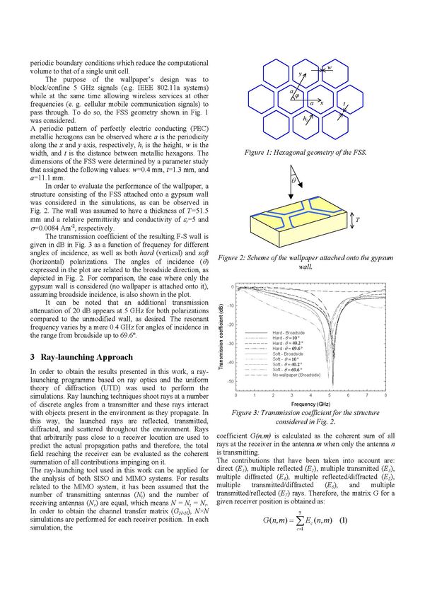
The purpose of the wallpaper's design was to
block/ confine 5 GHz signals (e.g. IEEE 802.11la systems)
while at the same time allowing wireless services at other
frequencies (e. g. cellular mobile communication signals) to
pass through. To do so, the FSS geometry shown in Fig. 1
was considered.
A periodic pattern of perfectly electric conducting (PEG)
metallic hexagons can be observed where a is the periodicity
along the x and y axis, respectively, hi is the height, w is the
width, and t is the distance between metallic hexagons. The Figure 1.- Hexagonal geometry of the FSS.
dimensions of the FSS were determined by a parameter study
that assigned the following values: w=0.4 mm, t--1.3 mm, and
a= 11.1Imm.
In order to evaluate the performance of the wallpaper, a
structure consisting of the FSS attached onto a gypsum wall
was considered in the simulations, as can be observed in
Fig. 2. The wall was assumed to have a thickness of T=51.5
mm and a relative permittivity and conductivity of c,=5 and
o--0.0084 Am 2, respectively. IT
The transmission coefficient of the resulting F-S wall is
given in dB in Fig. 3 as a function of frequency for different
angles of incidence, as well as both hard (vertical) and soft Figure 2.- Scheme of the wallpaper attached onto the gypsum
(horizontal) polarizations. The angles of incidence (6) walL.
expressed in the plot are related to the broadside direction, as
depicted in Fig. 2. For comparison, the case where only the
gypsum wall is considered (no wallpaper is attached onto it), 0
assuming broadside incidence, is also shown in the plot.
It can be noted that an additional transmission -10 [
attenuation of 20 dB appears at 5 GHz for both polarizations co
compared to the unmodified wall, as desired. The resonant -20 k
frequency varies by a mere 0.4 GHz for angles of incidence in Hard -Broadside
the range from broadside up to 69.60. 0
Hard -0 =1O0 1
-30 Hard -0 =40.2'
Cl) Hard -0 =69.6'
Soft -Broadside
3 Ray-launching Approach H-
Soft- 0=10O
-40
Soft -0 =40.2'
In order to obtain the results presented in this work, a ray- Soft -0 =69.6 o
No wallpaper (Broadside)
launching programme based on ray optics and the uniform -50
theory of diffraction (UTD) was used to perform the
simulations. Ray launching techniques shoot rays at a number 0 1 2 3 4 5 6 7 8
of discrete angles from a transmitter and these rays interact Frequency (GHz)
with objects present in the environment as they propagate. In Figure 3.- Transmission coefficient for the structure
this way, the launched rays are reflected, transmitted, considered in Fig. 2.
diffracted, and scattered throughout the environment. Rays
that arbitrarily pass close to a receiver location are used to coefficient G(n, m) is calculated as the coherent sum of all
predict the actual propagation paths and therefore, the total rays at the receiver in the antenna m when only the antenna n
field reaching the receiver can be evaluated as the coherent is transmitting.
summation of all contributions impinging on it. The contributions that have been taken into account are:
The ray-launching tool used in this work can be applied for direct (El), multiple reflected (E2), multiple transmitted (E3),
the analysis of both S150 and MIMO systems. For results multiple diffracted (E4), multiple reflected/diffracted (E5),
related to the MIMO system, it has been assumed that the multiple transmitted/diffracted (E6) and multiple
number of transmitting antennas (Ne) and the number of transmitted/reflected (E7) rays. Therefore, the matrix for a
receiving antennas (Nr) are equal, which means N =N, N,. given receiver position is obtained as:
In order to obtain the channel transfer matrix (GN,N), NxN 7
simulations are performed for each receiver position. In each G(,m n m
simulation, the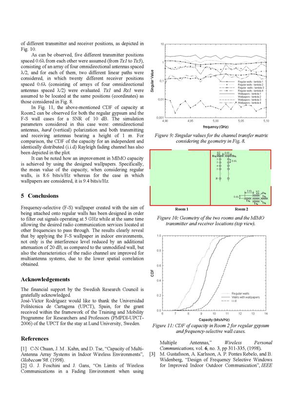
5m
where the direct, reflected, transmitted, diffracted,
reflected/diffracted,       transmitted/diffracted, and
transmitted/reflected components are calculated as:

                         E1(n,m)=              e -jkr      (2)                      5m
                                          r

                                               E
               E(n,m)=ZRi                           e            (3)
                                    i          ri
                                                                                         \

                                                                                                      Koom   I                      Koom .

               E3(n,m)              ZT, E           e-jk         (4)                     Figure 4. Geometry ofthe two rooms and the transmitter
                                     i         ri                                                           locations (top view).
      E4(n,m) = E               e-jksi   1Di                       -jksi    (5)

    E5(n,m)     =         Eoe   -jksi'D R                              e-jksi (6)
                     i    i

                                                                                    LL

                              e--jksi'D T|                 i            -jksI (7)   C)
   E6(n,m)=
                 i        i                    ISi      Si +Si)

              E7(n, m)             ZTRi ° e jkri (8)
                                         iri
                                                                        -60      -40     -20            20     40    60     80     100
where Eo is the emitted field strength, k is the wave number, r                                                  0

and ri are the propagation path lengths between the source n                                         SIR (dB)
and the receiver m, s' is the path length from the source to the                Figure 5. CDF of the SIR in Room 2.
diffracting wedge, s is the path length from the diffracting
wedge to the receiver, Di is the diffraction coefficient for            In Fig. 5, the cumulative distribution function (CDF) of
finitely conducting wedges given in [4], and Ti and Ri are the the signal to interference ratio (SIR) over every point in
transmission and reflection coefficients, respectively. In this Room 2 is depicted, considering the two cases where regular
case, Ti and Ri depend on the polarization of the incident gypsum walls are considered and wallpaper-gypsum walls are
wave, angle of incidence, permittivity, and conductivity.        assumed. The simulations were performed assuming
      For the analysis, it has been assumed that the transmitter omnidirectional antennas, a frequency of 5 GHz, soft
has no knowledge of the channel and that it distributes power (horizontal) polarization and both Tx] and Tx2 bearing a
equally among all transmitters [1].                              height of 1 m (which is the third coordinate that can be seen
                                                                 in the position of both transmitters).
                                                                 It can be observed how an improvement of about 20 dB in
4 Results                                                        SIR is achieved by using the F-S walls. This is in agreement
4.1 SISO Case                                                    with  expected values, according to Fig. 3.
                                                                        In order to evaluate the power delay profile (PDP)
                                                                 between      a transmitter and a receiver in Room 2 for both
An analysis of the use of the designed wallpapers in an indoor
environment was carried out using the mentioned ray-             regular    gypsum    and F-S wall cases, the scheme shown in Fig.
                                                                 6 was considered, where transmitter Tx] and receiver Rxl are
launching software, firstly for a SISO system, considering the
two-room floor plan (top view) depicted in Fig. 4, where located.
distances are expressed in meters.                                      In this case, the mentioned PDP can be observed in Fig.
As can be seen, the floor consists of two 5 x5 square rooms
                                                m2               7  for  both regular gypsum and F-S wall cases. The curves
                                                                 reveal   an average of 20 realizations undertaken at different
with two apertures each, bearing a width of 1.6 m (acting as
windows) and assumed to be infinitely high for the               frequencies      ranging from 4.9 to 5.1 GHz with a 0.01 GHz
simulations. Transmitter Tx] is located inside Room 2 so that    step.  Furthermore,      a low-pass filtering with cut-off at 40 MHz
it gives coverage to that area. Tx2 is located in Room 1 and     was    carried    out  in   the frequency domain by a Blackman
therefore, its signal becomes an interference when entering      window      for each  realization.  The simulations were performed
                                                                 assuming      omnidirectional     antennas,  a frequency of 5 GHz,
Room 2.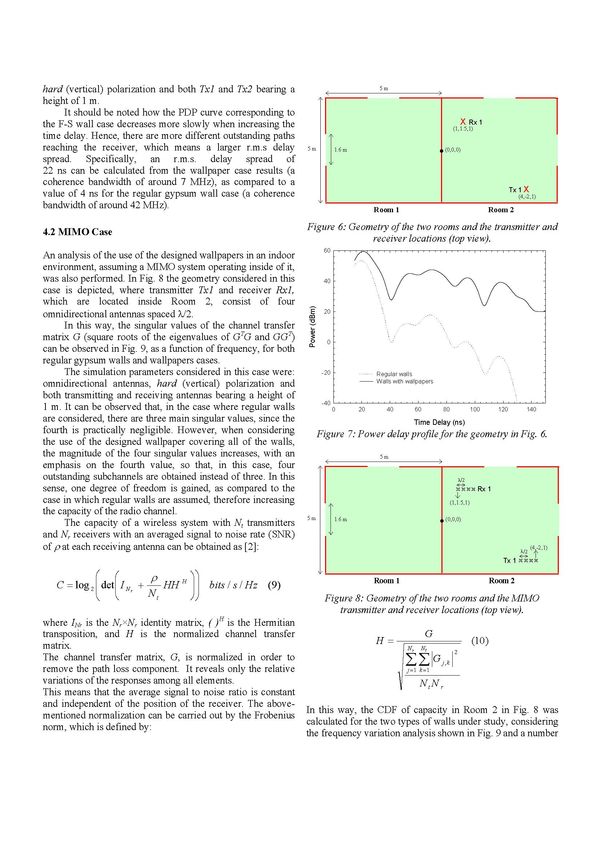
hard (vertical) polarization and both Tx] and Tx2 bearing a                                 5m

height of t m.
     It should be noted how the PDP curve corresponding to
the F-S wall case decreases more slowly when increasing the
time delay. Hence, there are more different outstanding paths
reaching the receiver, which means a larger r.m.s delay           5m
spread. Specifically, an r.m.s. delay spread of
22 ns can be calculated from the wallpaper case results (a
coherence bandwidth of around 7 MHz), as compared to a
value of 4 ns for the regular gypsum wall case (a coherence
bandwidth of around 42 MHz).                                                               Room 1                               Room 2

4.2 MIMO Case                                                     Figure 6. Geometry ofthe two rooms and the transmitter and
                                                                                 receiver locations (top view).
                                                                            bU
An analysis of the use of the designed wallpapers in an indoor                        .( I,
environment, assuming a MIMO system operating inside of it,
was also performed. In Fig. 8 the geometry considered in this               40
case is depicted, where transmitter Tx] and receiver Rxl,
which are located inside Room 2, consist of four
omnidirectional antennas spaced X/2.                              E         2U F

      In this way, the singular values of the channel transfer    0
                                                                  co
matrix G (square roots of the eigenvalues of GTG and GGT)                    0
can be observed in Fig. 9, as a function of frequency, for both
regular gypsum walls and wallpapers cases.
      The simulation parameters considered in this case were:               -20 F          Regular walls
omnidirectional antennas, hard (vertical) polarization and                                 Walls with wallpapers

both transmitting and receiving antennas bearing a height of
                                                                            -40
1 m. It can be observed that, in the case where regular walls                     0   20      40         60        80     100     120    140
are considered, there are three main singular values, since the                                         Time Delay (ns)
fourth is practically negligible. However, when considering            Figure 7. Power delay profilefor the geometry in Fig. 6.
the use of the designed wallpaper covering all of the walls,
the magnitude of the four singular values increases, with an                                5m
emphasis on the fourth value, so that, in this case, four              /t
outstanding subchannels are obtained instead of three. In this
sense, one degree of freedom is gained, as compared to the
case in which regular walls are assumed, therefore increasing
the capacity of the radio channel.                                5m
      The capacity of a wireless system with N, transmitters
and N, receivers with an averaged signal to noise rate (SNR)
of p at each receiving antenna can be obtained as [2]:
                                                                       \

                                                                                           Room                                 Room 2
   C =log2    detKIN,   + N HHH)         bits/s/Hz (9)                                             1

                                                                             Figure 8: Geometry of the two rooms and the MIMO
                                                                                transmitter and receiver locations (top view).
where INr is the NrxNr identity matrix, ()H iS the Hermitian
transposition, and H is the normalized channel transfer
matrix.                                                                         H            G
                                                                                                       (10)
The channel transfer matrix, G, is normalized in order to                              y       G
                                                                                                 j,k
remove the path loss component. It reveals only the relative                           j=i k=i
variations of the responses among all elements.                                            NtNr
This means that the average signal to noise ratio is constant
and independent of the position of the receiver. The above-      this way, the CDF of capacity in Room 2 in Fig. 8 was
mentioned normalization can be carried out by the Frobenius Incalculated for the two types of walls under study, considering
norm, which is defined by:
                                                              the frequency variation analysis shown in Fig. 9 and a number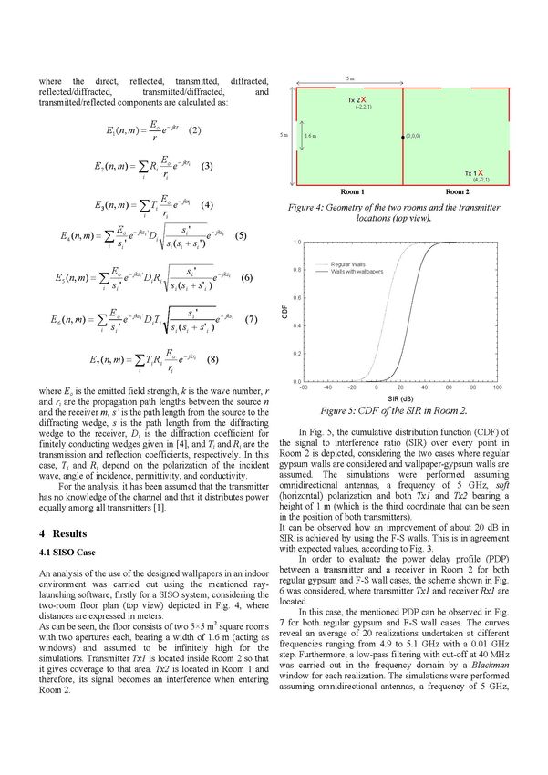
of different transmitter and receiver positions, as depicted in               InU,
Fig. 10.
      As can be observed, five different transmitter positions
spaced 0.6X from each other were assumed (from Tx] to Tx5),                    1
consisting of an array of four omnidirectional antennas spaced
X/2, and for each of them, two different linear paths were
considered, in which twenty different receiver positions                     011
                                                                                     7
                                                                                               I
                                                                                               _ _\
                                                                                                                  \/                \             +            Regular walls - lambda 1
                                                                   cn
spaced 0.6X (consisting of arrays of four omnidirectional                                                                                    -----
                                                                                                                                                               Regular walls - lambda 2
                                                                                                                                                               Regular walls -lambda 3
antennas spaced X/2) were evaluated. Tx] and Rxl were                                                                                        -.  -             P-Regular walls lambda 4
                                                                                                                                                               Wallpapers - lambda 1
assumed to be located at the same positions (coordinates) as                 011
                                                                                                                                        ..   .. ......   ...   Wallpapers- lambda 2
                                                                                                                                                               Wallpapers- lambda 3
those considered in Fig. 8.                                              0
                                                                                                      A~               A t"' .    / \-       -b          -     Wallpapers - lambda 4
      In Fig. 11, the above-mentioned CDF of capacity at
Room2 can be observed for both the regular gypsum and the
                                                                        0 001 L
F-S wall cases for a SNR of 10 dB. The simulation                              4,9(  0                     4,95              5,00                              5,05                   510
parameters considered in this case were: omnidirectional                                                               frequency (GHz)
antennas, hard (vertical) polarization and both transmitting
and receiving antennas bearing a height of 1 m. For                     Figure 9. Singular values for the channel transfer matrix
comparison, the CDF of the capacity for an independent and                         considering the geometry in Fig. 8.
identically distributed (i.i.d) Rayleigh fading channel has also
been depicted in the plot.
      It can be noted how an improvement in MIMO capacity
is achieved by using the designed wallpapers. Specifically,
the mean value of the capacity, when considering regular
walls, is 8.6 bits/s/Hz whereas for the case in which
wallpapers are considered, it is 9.4 bits/s/Hz.

5 Conclusions
Frequency-selective (F-S) wallpaper created with the aim of                                        Koom    I                                                   Koom   2
being attached onto regular walls has been designed in order
to filter out signals operating at 5 GHz while at the same time          Figure 10. Geometry of the two rooms and the MIMO
allowing the desired radio communication services located at                 transmitter and receiver locations (top view).
other frequencies to pass through. The results clearly reveal
that by applying the F-S wallpaper in indoor environments,
not only is the interference level reduced by an additional
attenuation of 20 dB, as compared to the unmodified wall, but
also the characteristics of the radio channel are improved for
multiantenna systems, due to the lower spatial correlation
obtained.
                                                                   LL
                                                                   C)

Acknowledgements
The financial support by the Swedish Research Council is
gratefully acknowledged.
Jose-Victor Rodriguez would like to thank the Universidad
Politecnica de Cartagena (UPCT), Spain, for the grant
received within the framework of the Training and Mobility                    6                7           8      9          10                 11              12         13             14
Programme for Researchers and Professors (PMPDI-UPCT-                                                             Capacity (bits/s/Hz)
2006) of the UPCT for the stay at Lund University, Sweden.          Figure               11.   CDF of capacity in Room 2 for regular gypsum
                                                                                               andfrequency-selective wall cases.
References
                                                                       Multiple      Antennas,"        Wireless       Personal
[1] C-N Chuan, J. M . Kahn, and D. Tse, "Capacity of Multi-            Communications, vol. 6, no. 3, pp 311-335, (1998).
Antenna Array Systems in Indoor Wireless Environments",            [3] M. Gustafsson, A. Karlsson, A. P. Pontes Rebelo, and B.
Globecom'98. (1998).                                                   Widenberg, "Design of Frequency Selective Windows
[2] G. J. Foschini and J. Gans, "On Limits of Wireless                 for Improved Indoor Outdoor Communication", IEEE
Communications in a Fading Environment when using
Transactions on Antennas and Propagation,
vol. 54, no.6, pp. 1897-1900, (2006).
[4] R. J. Luebbers, "Finite Conductivity Uniform GTD
versus Knife Edge Diffraction in Prediction of
Propagation Path Loss", IEEE Trans. on Antennas and
Propagation, vol. 32, no. 1, pp. 70-76, (1984).
[5] B. A. Munk, "Frequency Selective Surfaces: Theory and
Design", Wiley, New York, (2000).
[6] G. H. Sung, K. W. Sowerby, M. J. Neve, and A. G.
Williamson, "A Frequency-Selective Wall for
Interference Reduction in Wireless Indoor
Environments", IEEE Antennas and Propagation
Magazine, vol. 48, no. 5, pp. 29-37, (2006).
[7] G. H. Sung, K. W. Sowerby, and A. G. Williamson,
"Modeling a Low-Cost Frequency-Selective Wall for
Wireless-Friendly Indoor Environments", IEEE
Antennas and Wireless Propagation Letters, vol. 5, pp.
311-314, (2006).
[8] I. E. Telatar, "Capacity of Multi-Antenna Gaussian
Channel", European Transactions on
Telecommunications, vol. 10, no. 6, pp. 585-595, (1999).You can also read